MAINFINAL(ITEC3010)
1/219
There's no tags or description
Looks like no tags are added yet.
Name | Mastery | Learn | Test | Matching | Spaced | Call with Kai |
|---|
No analytics yet
Send a link to your students to track their progress
220 Terms
Use Case Realization
Process of elaborating the detailed design with interaction diagrams for a particular use case
Interaction Diagram
Shows how objects work together to carry out a use case. Includes Sequence Diagrams and Communication Diagrams.
Sequence Diagram
An interaction diagram that focuses on the order of messages over time between objects.
Communication Diagram
Structure-focused diagram showing which objects communicate and what messages are sent
Use Case Controller
A designer-created class that links UI to business logic, coordinates tasks, and handles user actions.
Message Flow
The typical path of interaction: Actor → Boundary (UI) → Controller → Entities (data).
Purpose of Controller
To reduce coupling, increase cohesion, and make the system more reusable and easier to modify.
Use Case Controller Features
One controller per use case (e.g., CartController), it’s an artificial class that coordinates logic without containing business rules.
Actor
Represents an external role of the person or thing that initiates the use case by sending the initial message
Object
instantiated class objects that perform actions to help carry out the use case
Link
connectors that illustrate the flow of messages
Messages
primary element of a communication diagram
True/false condition (optional)
if true the message is sent, if false the message is not sent
Sequence number
identifies the order of messages
Return-value
the type of value that the message returns after the completion of the service requested in a forward message. Basically the method return value.
Message-name
usually camelCase. Should be named informatively.
Parameter list
items of data that are passed to the destination object via the message. Basically the arguments of the method.
Activation lifelines
show the period during which a method of an object is alive and executing
Lifelines
Show the passage of time
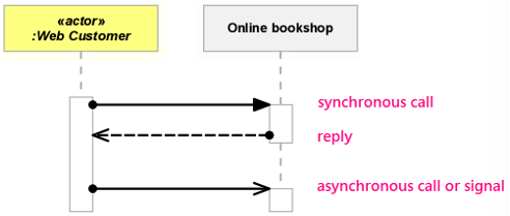
Synchronous Message (Synchronous Call)
- Filled arrow head
- Message is sent from source lifeline to target lifeline
External Systems (Analysis)
Identify all systems your system must connect to or exchange data with.
Technology Architecture (Design)
Specifies message formats, web/network addresses, communication protocols, security, and error handling.
User Interface (UI)
Part of the system users interact with, involving mockups, tools, models, storyboards, and prototypes.
User Experience (UX)
The broader scope of UI design, focusing on how users feel and interact with the system overall.
Centralized vs Distributed
Centralized systems run from one location, while distributed systems operate across multiple locations or servers.
Normalization
Organizing a relational database using normal forms to minimize redundancy and ensure data integrity.
Controls
mechanisms and procedures built into a system to safeguard the system and the information within
Integrity controls
controls that reject invalid data inputs, prevent unauthorized data outputs, protect data and programs against tampering
Input Controls
controls that prevent invalid or erroneous data from entering the system
Value limit controls
controls that check numeric data input to ensure that that value is reasonable, e.g. must be greater than zero
Completeness controls
controls that ensure that all required data values describing an object are present
Data validation controls
controls that ensure that numeric fields that contain codes or identifiers are correct
Field combination controls
controls that review combinations of data inputs to ensure that the correct data are entered
Output controls
controls that ensure that output arrives at the proper destination, which are “Accurate, current and complete”.
Security controls
controls that protect the assets of an organization from all threats
Access controls
control that limits a users ability to access resourses.
Authentication
process of identifying users who request access to access controlled resources
Authorization
process of allowing or restricting a specific authenticated users access to a specific resource based on access controls
CRUD
Create, Read (or Report), Update, and Delete — the 4 basic operations on data. Step 1: Identify all domain classes in the system. Step 2: For each class, ensure there are use cases to Create, Read/Report, Update, and Delete or archive instances. Step 3: Add any missing use cases and identify the stakeholders responsible for them. Step 4: Assign each action to the application or system responsible for carrying it out (e.g., which app handles "create").
Encryption
cryptographically altering data to be undecipherable to those without the key (Requires an algorithm; Requires a key (or multiple keys))
Decryption
convert encrypted data back to its original state
Symmetric key encryption
uses the same key to encrypt and decrypt
Asymmetric key encryption
uses different keys to encrypt and decrypt
Public key encryption
uses public key to encrypt and private key to decrypt
Digital Certificates
has an institutions name and public key
Architectural Concepts
Technology Architecture
The set of computing hardware, network hardware, and system software employed by an organization
Application Architecture
The set of information systems (including software applications) that an organization needs to support its strategic plan or fulfill its business goals
Distributed Architecture
Distribution of system components (hardware and software) across multiple geographic locations
Client/Server Architecture
server manages system resources and provides access to the resources, client communicates with the server to request resources
Three-layer Architecture
• View layer: accepts user input and displays outputs
• Business logic layer: (aka domain layer) implements the rules and procedures of business processing
• Data layer: manages stored data, usually in databases
Location Diagram
model that shows the geographic placement of systems components
Network Diagram
Model that shows how locations and hardware components are interconnected
Deployment Diagram
Model that shows how software components are distributed across hardware components
Structure Chart
A hierarchical model (not UML) that shows how software modules relate and break down functions.
Top-Down Decomposition
Higher-level control modules call lower-level modules to perform detailed tasks.
Data Couple (Open Circle Arrow)
A single piece of data passed between modules.
Control Couple (Closed Circle Arrow)
A flag or signal passed between modules to control logic (may not be used, just checked).
Object-Oriented Program
A system built from classes and objects that interact using methods to perform business tasks.
Class
A blueprint that defines the properties and behaviors of objects.
Object
A specific instance of a class that can send and receive messages.
Object Responsibility
Objects should know what they need to know and do what they’re responsible for in system logic.
Separation of Responsibility
Classes should be grouped (e.g., into packages) based on their main purpose or role.
Stereotypes
UML tags (like <
Protection from Variations
Stable parts of the system (like customer data) are kept separate from parts that change more often (like sales logic).
Cohesion
The degree to which elements within a module belong together; highly cohesive classes have one clear focus, allowing them to operate independently.
Coupling
The level of dependency between modules; ideally low so that changes in one module minimally impact others.
Encapsulation
The practice of bundling data with its associated functions, using access modifiers to hide internal state and improve module cohesion.
CRC Cards
A brainstorming tool that outlines a class’s Name, Responsibilities (what it stores, does, or is accountable for), and Collaborations (which other classes it uses), emphasizing “what” over “how.”
<<controller>>
A designer-created class that mediates interactions between the UI (via a <
<<entity>>
A class representing a real-world object or data that is persistent across system operations.
Method
A function defined inside a class that performs an action or behavior related to the object (e.g., startEngine()in Car).
Stereotype
A UML label (e.g., <
Entity Class
A class that represents real-world objects or data users deal with; usually persistent beyond program execution.
Boundary Class (View Class)
A class that handles interaction between the user and the system; typically UI or system interfaces.
Controller Class
A class that mediates between boundary and entity classes, coordinating tasks or managing complex logic.
Data Access Class
A class responsible for retrieving and updating data in a database, often executing SQL queries.
Visibility
Defines access to attributes/methods; + = public (visible), - = private (invisible to other objects).
Data Type
The kind of value an attribute or method uses (e.g., int, string, bool, float).
Property
Usually refers to a key attribute like a primary key used for uniquely identifying a database record.
Parameter
Also called an argument; the input data passed into a method.
Return Type
The type of value a method sends back after it runs (e.g., bool, int, string).
First-Cut Design Class Diagram
An early version of a class diagram that expands domain classes with attributes, but not yet with methods.
Predictive Approach
Assumes the project can be fully planned in advance and developed according to a fixed structure.
Adaptive Approach
Assumes requirements may change and the project must remain flexible throughout development.
Predictive Characteristics
Clear requirements, minimal new processes, traditional, planning-heavy, structured.
Predictive SDLC Phases
Initiation – Define the problem and get approval to proceed.
Planning – Organize, schedule, and map out the project structure.
Analysis – Understand the business need and system requirements.
Design – Plan how the system will be structured and built.
Implementation – Code, test, and integrate system components.
Deployment – Install and make the system operational.
Support – Maintain, update, and improve the system post-launch.
Waterfall Model
A traditional SDLC approach where phases are completed sequentially with rigid planning and no overlap.
Modified Waterfall Model
A slightly more flexible but still predictive approach, allowing limited overlap between phases; best for small, low-risk projects.
Adaptive Approach (Iterative)
Breaks the project into small iterations, where each mini-project goes through its own SDLC cycle (analysis → design → build → test).
Walking Skeleton
An early, barebones system structure built in a few iterations that covers end-to-end functionality and is expanded over time.
Evolutionary Prototype
A system built incrementally with minimal initial features and modified based on user and customer feedback.
Methodology
A structured set of guidelines and models that support every phase of the SDLC.
Technique
A specific set of guidelines that helps complete an SDLC task or activity.
Agile
A flexible, iterative approach that focuses on delivering only necessary models with just enough detail for rapidly changing environments.
Agile Examples
Agile Unified Process, Extreme Programming (XP), and Scrum.
Implementing Agile
Requires stakeholder buy-in, a chosen framework, empowered teams, and a collaborative, self-managed project environment.
Agile Advantages
Quick feedback loops, high team morale, faster problem-solving, and improved project control.
Agile Disadvantages
Less useful for small projects and may lack deep design focus.
Fragmented Output
A side effect of incremental delivery where not all system features are delivered at once.