simple machines
1/32
There's no tags or description
Looks like no tags are added yet.
Name | Mastery | Learn | Test | Matching | Spaced |
|---|
No study sessions yet.
33 Terms
simple machine functions
Change energy from one form to another
Example: Hydroelectric generator turns water energy into electricity.
Transfer forces
Example: Car transmission moves force from engine to wheels.
Change the direction of a force
Example: Pulling down on a rope to raise a flag up.
Change the size (magnitude) of a force
Example: Pulleys let you lift heavy stuff with less effort.
Change the distance or speed of movement
Example: Bicycle rear wheel moves faster and farther than pedal sprocket.
what is the level and inclinded family
The lever family consists of the lever, the pulley, the wheel and axle, and gears.
The inclined family consists of the inclined plane, the wedge, and the screw.
the lever family of machines
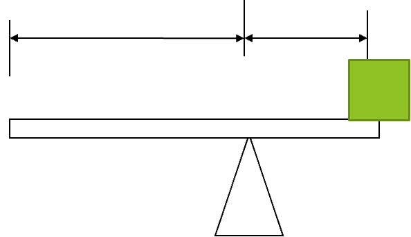
A lever is a stiff bar that pivots (rotates) around a point called the fulcrum.
You push on one end with an effort force (FE) to move something on the other end called the load, which pushes back with a load force (FL).
Two important distances on a lever:
Effort arm (dE): distance from the fulcrum to where you apply the effort.
Load arm (dL): distance from the fulcrum to the load.
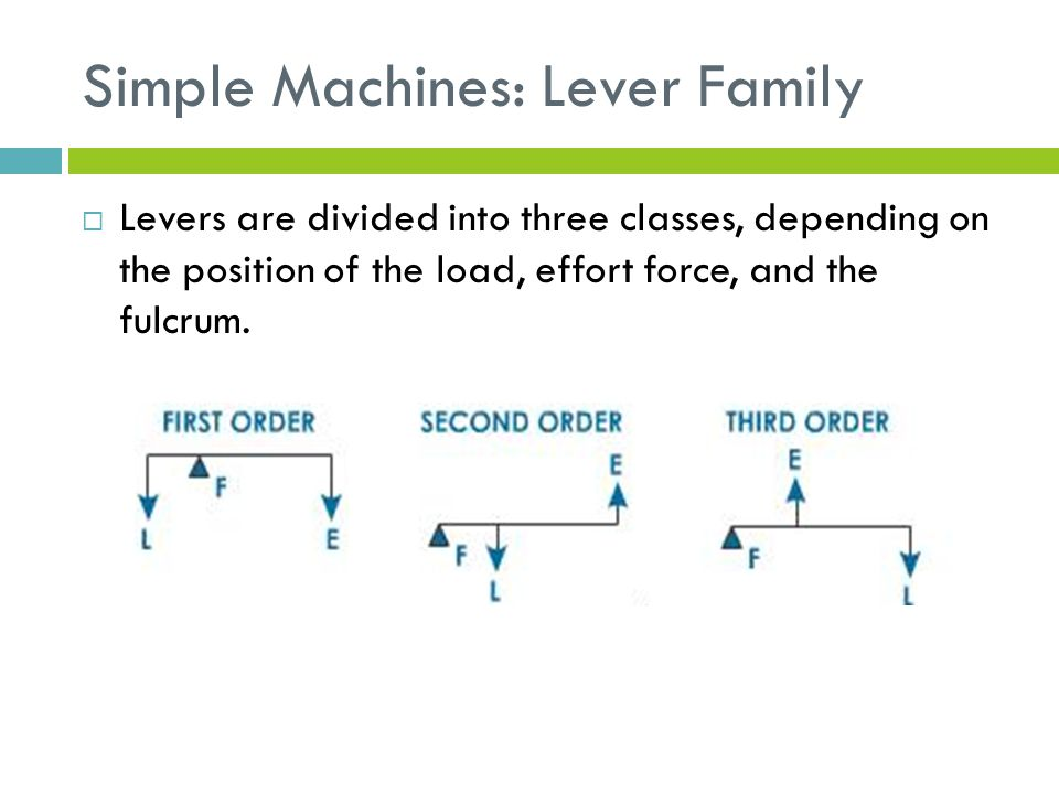
Levers are divided into three classes, depending on the position of the load, effort force, and the fulcrum.
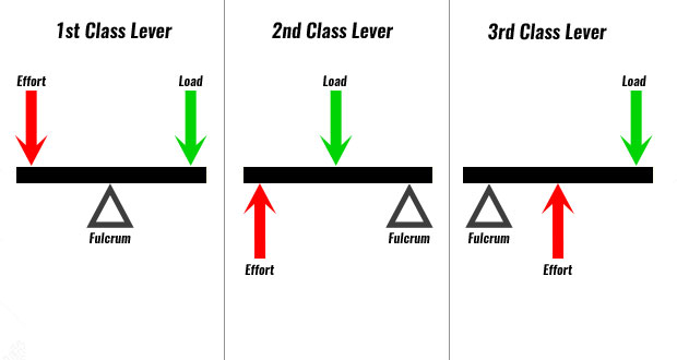
FLE, LFE, EFL:
First Class Lever → Fulcrum in the middle
→ Example: Seesaw
Effort — Fulcrum — Load
Second Class Lever → Load in the middle
→ Example: Wheelbarrow
Effort — Load — Fulcrum
Third Class Lever → Effort in the middle
→ Example: Tweezers / Your arm
Fulcrum — Effort — Load
A pulley
a wheel with a grooved part of the lever family of machines. The wheel rotates around a central fulcrum
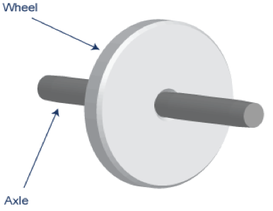
A wheel and axel
is a large diameter, rigid, circular disk (the wheel) connected to a small diameter, ridged rod (the axel).
Gears
are toothed wheels of different diameters linked together to increase the decrease the speed or to change direction.
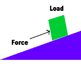
Inclined Plane
A ramp that increases the load that can be raised by an effort force.
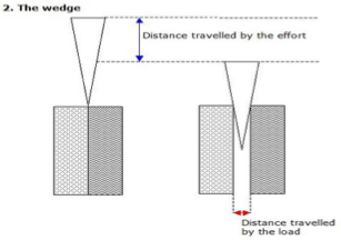
wedge
A double inclined plane that increases the applied or effort force.
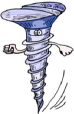
Screw-
Screw-An inclined plane wrapped around a central shaft that can turn
when is a torque applied
When a force or set of forces causes a rigid body to rotate,
Torque
– the turning effect caused by a force on a rigid object around a axis or fulcrum, symbol T;
it is measured in Newton-meters, or Nm;
it can be called a “moment force”
ex. Every time you open a door, you are producing a torque on the door.
A small force applied far from the hinges can produce the same amount of torque as a large force applied closer to the hinges.
In order to create the largest amount of torque possible when pushing on the door, the force generated must be at a 90 degree angle to the door.
Example 2
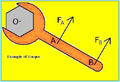
The amount of torque produced depends on two factors.
The magnitude of the force (F) applied to the rigid object.
The distance (d) between the force and the axis or fulcrum.
T increases as F increases ( T F)
T increases as d increases ( T d)
Torque = force x distance or T = Fd (where F is perpendicular to the ridge object)
torque on levers
A torque is the turning force on a lever.
There are two types of torque:
Effort torque (TE) – caused by your force (effort)
Load torque (TL) – caused by the weight or load
Each torque depends on how far the force is from the fulcrum:
Effort distance (dE) = distance from fulcrum to effort
Load distance (dL) = distance from fulcrum to load
Effort torque = effort force x effort arm
Load Torque = load force x load arm
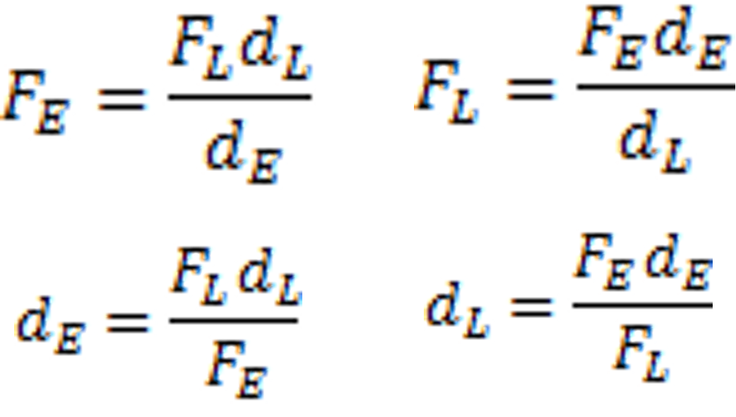
law of the lever
When a lever is in static equilibrium(moving in any direction or rotating), the magnitude of the effort torque equals the magnitude of the load torque.
This law can be written in the equation form
Effort torque = load torque
Effort force x effort arm = load force x load arm
A lever is balanced when the clockwise torque = counterclockwise torque.
🔄 In short:
TCW = TCCW
Where:
TCW = torque turning clockwise
TCCW = torque turning counterclockwise
Wheels can be levers
A wheel on an axle is like a circular lever.
The pivot (fulcrum) is the center of the axle.
Force Multipliers
Example: Steering wheel
A larger wheel makes it easier to turn the axle with less effort.
Big wheel = more turning force (torque)
Speed Multipliers
Example: Car wheels
The motor puts a strong force on the axle, and the wheel spins faster.
Big force = more speed at the wheel
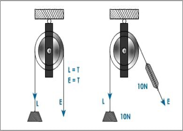
pullys
A pulley is like a wheel with a groove that holds a rope or cable.
It works like a lever, with the axle as the pivot.
🔄 Simple Pulley:
Lets you pull down to lift up.
Changes the direction of the force, not the amount.
Makes lifting feel easier, but force size stays the same.
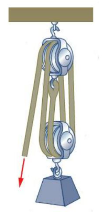
🏗 Multiple Pulleys (Force Multiplier):
More pulleys = less effort to lift a heavy load.
You pull over a longer distance, but with less force.
Used in systems like a block and tackle.
📦 Block and Tackle:
Block = casing around the pulleys
Tackle = the rope or cable
How to Calculate Effort in a Pulley System
Effort = Load ÷ Number of supporting ropes
Important: Don’t count the rope going to your hand (effort rope).
🔍 Example:
Load = 200 kg
4 ropes holding the load (not counting the one you're pulling)
Effort = 200 ÷ 4 = 50 kg
So the person feels like they are only lifting 50 kg!
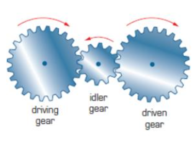
driving and driven gears
The first gear that turns is called the driving gear.
The gears that it turns are called driven gears.
🔧 Two Types of Gear Systems:
Force Multiplier
Small driving gear → Big driven gear
More force, but slower
Good for lifting heavy things
Speed Multiplier
Big driving gear → Small driven gear
More speed, but less force
Good for making things spin fast
idler gears
u An idler gear can be used in a gear combination to make the driving and driven gears rotate in the same direction.
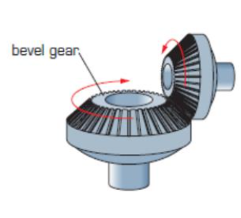
Bevelled Gears
Bevelled gear wheels are positioned at right angles to each other • This changes the plane of rotation.
Used in hand-drills and in many other machines.
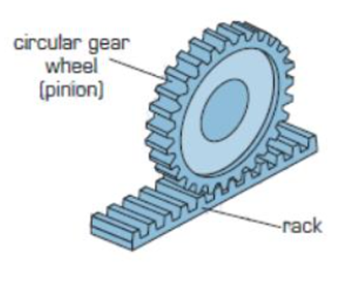
Rack and Pinion Gears
Rack and pinion gears are made up of a row of teeth (called the rack), and a gear wheel that rolls on top of this.
One use of this type of system is to stop mountain trains slipping on steep slopes.
bike gears
The gears used in a bicycle are called sprockets.
The pedal and crank are attached to a gear sprocket called the chain wheel.
A chain connects this to the rear sprocket.
Pedalling turns the chain wheel, which turns the rear wheel, via the chain
gear ratios
Are calculated by dividing the number of teeth on the driving sprocket by the number of teeth on the driven sprocket.
GR = teeth on driver teeth on driven gear
Example:
If the driving gear has 9 teeth and the driven gear has 3
GR=9/3=3
mechinical advantage (MA)
Expressed in a ratio WITH NO UNITS!!
The number of times a machine multiplies the input force.
Simple machines allow us to move objects with less effort force then the load force due to force advantage.
The force advantage can be found by dividing the load force by the effort force,
FL /FE
2 Types of Mechanical Advantage
IDEAL (IMA)
Involves no friction.
Is calculated differently for different machines
Usually input distance/output distance
ACTUAL (AMA) - The higher the Mechanical Advantage, the easier it is to move something.
Involves friction.
Calculated the same for all machines
Usually Output force/Input Force
Different mechanical advantages:
Mechanical advantage greater than one
Output force is greater than input force.
As MA increases, the distance the output force moves decreases.
MA equal to one. (output force = input force)
Change the direction of the applied force only.
Mechanical advantage less than one
An increase in the distance an object is moved (dr)
Efficiency
The percentage of the work input that becomes work output in a machine.
𝐸𝑓𝑓= (〖𝑊𝑜𝑟𝑘 𝑂𝑢𝑡𝑝𝑢𝑡 (𝑊〗_𝑜) )/( 〖𝑊𝑜𝑟𝑘 𝐼𝑛𝑝𝑢𝑡 (𝑊〗_𝑖)) x 100%
Efficiency can never be greater than 100 %. Why?
- Some work is always needed to overcome friction.
A machine that is 100% efficient is called an ideal machine.
- Ideal machines do not exist because we have been unable to completely overcome friction.
percent efficiency
Percent Efficiency – the ratio of the AMA to the IMA of a machine, expressed as a percentage. Machines with large amounts of friction will have a low percent efficiency.
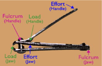
Domestic Machines
A common example of a domestic compound machine is nail clippers. A nail clipper contains two levers.
A second class lever and a third class lever. The cutting blades themselves are also simple machines as they are inclined planes.
industrial machines
Large, compounds machines are used in many industries.
A common simple machine used is the pulley, in some cases the more than one pulley will be used to increase the force.
Two common pulley designs are the block and tackle and the chain hoist.
Block and Tackle – Simplified
Found on cranes and heavy machines.
Has two sets of pulleys on the same axis:
Upper set: fixed to support
Lower set: attached to the load
One rope winds around both sets.
Pulling the rope lifts the lower pulleys and the load.
⚖ Ideal Mechanical Advantage (IMA):
IMA = number of supporting rope strands
(Count all rope parts holding up the load)
Chain Hoist – Simplified
Has 3 pulleys and an endless chain looped around them.
Upper two pulleys: fixed, have teeth, and are joined together.
Lower pulley: moves up and down with the load.
🔢 Ideal Mechanical Advantage (IMA):
IMA = (Radius of bigger fixed pulley) ÷ (Radius of smaller fixed pulley)
Or,
IMA = Number of teeth on bigger pulley ÷ Number of teeth on smaller pulley
🔧 Other chain hoists:
Use a separate pull chain and a triple gear reduction system.
This helps lift very heavy loads with less effort.