Waves
1/54
There's no tags or description
Looks like no tags are added yet.
Name | Mastery | Learn | Test | Matching | Spaced | Call with Kai |
|---|
No analytics yet
Send a link to your students to track their progress
55 Terms
Wave Energy Transfer
Waves travel through a medium, causing particles to oscillate
Energy is transferred between particles
Particles remain in the same place overall (no matter is transferred)
Labelling a wave
Amplitude: maximum displacement of a point on a wave from its undisturbed position
Wavelength: distance between the same point on two adjacent waves
Frequency: number of complete waves passing a point per second (measured in Hz, where 1 Hz = 1 wave per second
Transverse Waves
Oscillations (vibrations) are perpendicular (90°) to the direction of energy transfer
All electromagnetic waves are transverse
Examples: ripples and waves in water, waves on a string
Longitudinal Waves
Oscillations (vibrations) are parallel to the direction of energy transfer
They have regions of compression and rarefaction
Examples include sound waves in air, ultrasound, and shock waves
Using an Oscilloscope to measure the speed of sound
Attach a signal generator to a speaker to produce sound at a specific frequency
Use two microphones connected to an oscilloscope to detect the sound waves
Set up the oscilloscope so each microphone’s wave is shown separately
Start with both microphones next to the speaker, then slowly move them apart until the two waves are aligned on the display but have moved exactly one wavelength apart
Measure the distance between the microphones — this gives one wavelength
Use speed = frequency × wavelength to calculate the speed of sound in air
The speed of sound in air is approximately 330 m/s
Repeat the experiment and check results are similar for reliability
How to measure the speed of water ripples using a lamp? RP
Use a signal generator attached to a ripple tank dipper to produce waves at a set frequency
Use a lamp to project wave crests onto a screen below the tank, making sure the wave shadows are the same size as the waves
Measure the distance between shadow lines (each gap = one wavelength)
Measure across 10 wavelengths and divide by 10 to find the average wavelength
Use v = f × wavelength to calculate wave speed
This method is useful for investigating wave speed and measuring wavelength without disturbing the waves
Standing Waves on a String RP
Set up the apparatus with a signal generator, vibration transducer, string, pulley, and hanging masses
Turn on the signal generator so the vibration transducer makes the string vibrate
Adjust the frequency until a clear standing wave pattern is formed on the string
The required frequency depends on the length of string between the pulley and transducer and the masses used
Measure the wavelength by measuring the length of 4 or 5 full wavelengths as accurately as possible in one go
If measuring half wavelengths, double the value to get a full wavelength
The frequency of the wave is whatever you set on the signal generator
Use v = f × wavelength to calculate the wave speed
Waves at a Boundary
When waves arrive at a boundary between two different materials, three things can happen:
The waves can be absorbed by the material they are trying to enter, transferring energy to the material’s energy stores (e.g. microwaves heating food)
The waves can be transmitted, continuing to travel through the new material (often changing direction due to refraction)
The waves can be reflected
What happens depends on the wavelength of the wave and the properties of the materials involved
Reflection of a Wave
Angle of incidence = angle of reflection
The angle of incidence is the angle between the incoming wave and the normal
The angle of reflection is the angle between the reflected wave and the normal
The normal is a line drawn perpendicular (90°) to the surface at the point where the wave hits the boundary
The normal is usually shown as a dotted line
Reflection of Waves
-Specular
-Diffuse
Specular reflection happens when a wave is reflected in a single direction by a smooth surface. For example, when light is reflected by a mirror you get a clear reflection.
Diffuse reflection is when a wave is reflected by a rough surface (like paper). The reflected rays are scattered in lots of different directions.
This happens because the normal is different for each incoming ray, so the angle of incidence is different for each ray. The rule angle of incidence = angle of reflection still applies.
When light is reflected by a rough surface, the image appears blurred or less shiny and you do not get a clear reflection of objects.
EM waves
All electromagnetic (EM) waves are transverse waves that transfer energy from a source to an absorber
Hot objects transfer energy by emitting infrared radiation, which is absorbed by the surrounding air
All EM waves travel at the same speed through a vacuum or air
EM waves form a continuous spectrum and are grouped into 7 types: radio waves, microwaves, infrared, visible light, ultraviolet, X-rays, gamma rays
Mnemonic: Raging Martians Invaded Venus Using X-ray Guns (Radio → Gamma order)
Radio waves have the lowest frequency and the longest wavelength → increasing frequency and decreasing wavelength
The large range in EM waves exists because they are produced by different changes in atoms and nuclei
Nuclear changes produce high-energy waves like gamma rays, while less energetic changes produce lower-frequency waves like radio waves
This explains why different materials absorb different frequencies of EM waves
Each type of EM wave is used for different purposes depending on its energy and properties
Refraction- waves changing direction at a boundary
When a wave crosses a boundary between materials at an angle, it is refracted (changes direction)
Refraction happens because the wave speed changes in different materials
Generally, waves travel slower in more optically dense materials
If a wave slows down → it bends towards the normal
If a wave speeds up → it bends away from the normal
The frequency stays the same, but the wavelength changes
Optical density is how fast light travels in a material (higher optical density = slower light)
Mnemonic: TAGAGA
Towards the normal = Air → Glass (slower medium)
Away from the normal= Glass → Air (faster medium)
How to construct ray diagrams?
Start by drawing the boundary between two materials and the normal line (90°) at the point where the wave hits the boundary
Draw the incident ray meeting the normal at a point — the angle between the ray and normal is the angle of incidence
If given this, draw it carefully with a protractor
Now draw the refracted ray in the second material
If the second material is more optically dense than the first, the ray bends towards the normal
The angle of refraction is smaller than the angle of incidence
If the second material is less optically dense, the ray bends away from the normal
The angle of refraction is larger than the angle of incidence
Key rule:
Into denser medium → towards the normal
Into less dense medium → away from the normal
For Experiments what to always do involving light rays?
Do experiments in dim rooms so clearly see light rays, then use either a ray box or laser to produce thin rays of light so you can easily trace the ray and measure angles
Refraction in Different Materials RP
The boundary between different substances refracts light by different amounts
You can investigate this by looking at how much light is deviated when it passes from air into different materials
Place a rectangular block on a piece of paper and trace around it
Use a ray box or laser to shine a ray of light at the middle of one side of the block
Trace the incident ray and mark where the ray emerges from the other side
Remove the block and use a ruler to join the incident point to the emerging point to show the path of the refracted ray through the block
Draw the normal at the point where the ray enters the block
Use a protractor to measure the angle of incidence and angle of refraction
Repeat with different rectangular blocks made of different materials, keeping the incident angle the same throughout
How different materials reflect light by different amounts? RP
Take a piece of paper and draw a straight line across it
Place a mirror on the line so one edge lines up with it
Shine a ray of light at the mirror surface and trace the incident and reflected rays
Draw the normal at the point where the ray hits the mirror
Use a protractor to measure the angle of incidence and angle of reflection and record the values in a table
Repeat the experiment with different angles of incidence
Smooth surfaces like mirrors give specular reflection, producing a clear, thin, bright reflected ray
Rough surfaces cause diffuse reflection, where the reflected rays are scattered and less clear
The angle of incidence = angle of reflection
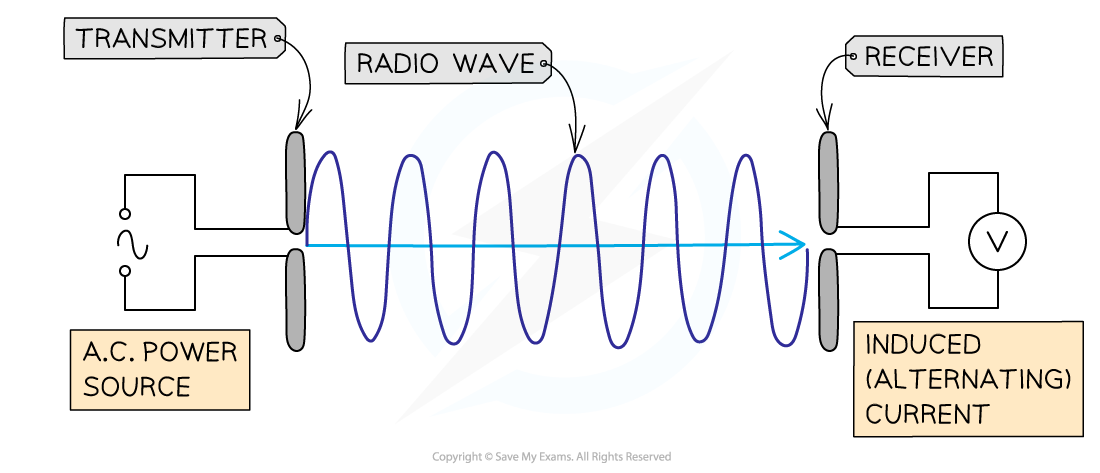
EM Waves and Radio waves
EM waves are made up of oscillating electric and magnetic fields
Alternating current (AC) is made up of oscillating charges
As charges oscillate, they produce oscillating electric and magnetic fields, forming electromagnetic waves
The frequency of the waves produced = frequency of the alternating current
Radio waves can be produced using an alternating current in an electrical circuit
The device where charges oscillate to create radio waves is called a transmitter
When transmitted radio waves reach a receiver, they are absorbed
The energy carried by the wave is transferred to the electrons in the material of the receiver
This causes electrons to oscillate, producing an alternating current
The circuit produces a current with the same frequency as the original radio wave
Radio Waves and Diffraction
Radio waves are electromagnetic radiation with wavelengths longer than about 10 cm
Long-wave radio waves (1–10 km) can travel long distances because they diffract (bend) around the curved surface of the Earth
Long wavelengths can also diffract around hills, tunnels, and other obstacles
This allows signals to be received even when the receiver is not in direct line of sight
Radio Waves and the Ionosphere / Uses
Short-wave radio signals (10–100 m) can travel long distances because they are reflected by the ionosphere (a charged layer in Earth’s upper atmosphere)
The ionosphere reflects signals back to Earth, depending on atmospheric conditions and time of day
Medium-wave signals may also reflect from the ionosphere depending on conditions
Very short wavelength waves (e.g. TV and FM radio) travel by line of sight, so they need a direct path between transmitter and receiver
Bluetooth uses short-range radio waves to transfer data wirelessly over small distances
Uses of Microwaves-satellites
Communication to and from satellites uses microwaves because they pass easily through the Earth’s atmosphere
The signal from a transmitter is sent into space
It is picked up by a satellite receiver dish orbiting thousands of kilometres above Earth
The satellite then transmits the signal back to Earth in a different direction
The signal is received by a ground-based dish
There is a time delay between sending and receiving the signal because of the long distance it travels
Uses of Microwaves- Ovens
In a microwave oven, microwaves are absorbed by water molecules in food
The microwaves penetrate a short distance into the food before being absorbed
This transfers energy to the water molecules, making them vibrate faster
The water molecules then transfer this energy to other particles in the food by heating
This causes the food to heat up and cook quickly
Uses of Infrared radiation
Infrared (IR) radiation is given out by hot objects
The hotter the object, the more IR radiation it emits
Infrared cameras detect IR radiation and convert it into an electrical signal
The signal is displayed as an image
Hotter objects appear brighter on the image
Absorbing IR radiation increases temperature
Food can be cooked using IR radiation because it increases the thermal energy of the food
Uses of IR Radiation - heaters
Electric heaters
Electric heaters warm a room using a long wire (heating element)
When current flows, the wire heats up
The wire emits infrared radiation (and some visible light)
This radiation is absorbed by objects and air in the room
Energy is transferred, increasing the temperature of the surroundings
Uses of Visible light
Optical fibres are thin glass or plastic fibres that carry data over long distances using visible light
They work because of total internal reflection
Light rays are reflected repeatedly inside the fibre until they reach the end
They use visible light as the signal carrier
Light is not easily absorbed or scattered as it travels along the fibre
The fibre has cladding, which helps keep light inside the core and protects the signal - cladding protects the fibre
Uses of UV Radiation
Fluorescence is a property of some chemicals where UV radiation is absorbed and then visible light is emitted
This is why fluorescent colours look very bright — they are actually emitting light
In a fluorescent lamp, UV radiation is produced and absorbed by a phosphor coating inside the tube
The phosphor then re-emits the energy as visible light
These lamps are energy efficient and useful for long periods of lighting
Security pens can be used to mark property
The marks are invisible in normal light but glow under UV light
Sunbeds use UV radiation to give an artificial tan
However, UV exposure can be dangerous to skin
Uses of X-Rays and Gamma Rays
Radiographers use X-rays to check for broken bones
X-rays pass through soft tissue (flesh) but are absorbed by dense materials like bone and metal
This creates an image showing the inside of the body
X-rays and gamma rays are used to treat cancer
Their high energy can kill living cells, including cancer cells
They are carefully directed to target tumour cells
Gamma rays can also be used as a medical tracer
A gamma-emitting substance is injected into a patient
It is tracked as it moves through the body to show how organs are working
Both X-rays and gamma rays are harmful
Protection includes lead aprons, lead screens, and limiting exposure to reduce risk
EM Radiation that is harmfull
The effect of electromagnetic waves depends on how much energy they transfer
Low-frequency waves (e.g. radio waves) transfer very little energy
They can pass through soft tissue without being absorbed much
High-frequency waves (e.g. X-rays and gamma rays) transfer large amounts of energy
This can cause damage to cells and tissues
Ultraviolet (UV) radiation can damage skin cells
It can cause sunburn, premature skin ageing, and increase the risk of skin cancer
X-rays and gamma rays are ionising radiation
They have enough energy to remove electrons from atoms
This can cause ionisation, leading to mutations in DNA and cancer
How to measure the risk of Radiation?
Radiation can be useful, for example in medicine and communication
Radiation dose is measured in sieverts (Sv)
A sievert is a measure of the risk of harm to the body from radiation exposure
It is not a measure of the total amount of radiation energy absorbed
The risk depends on:
The total dose of radiation absorbed
How harmful the type of radiation is
A large dose in sieverts means a higher risk of damage to the body
Small doses are less harmful, but repeated exposure can still build up risk
How does risk of radiation vary with body parts?
CT scans use X-rays + computer processing to produce detailed body images
They show how much radiation is absorbed by different tissues
Typical doses:
Head scan ≈ 2 mSv
Chest scan ≈ 8 mSv
A chest scan gives about 4× more radiation than a head scan
Higher dose means a higher risk of damage to body cells
Lenses
Convex lens
A convex lens bulges outward
It causes parallel rays of light to be brought together (they converge)
The point where they meet is the principal focus
Concave lens
A concave lens curves inward
It causes parallel rays of light to spread out (they diverge)
The rays appear to come from a virtual principal focus
Key terms
The principal axis is a line through the centre of the lens
The principal focus is the point where rays meet (or appear to come from)
The focal length is the distance from the centre of the lens to the principal focus
Rules for refraction in Convex lens
A ray parallel to the principal axis refracts through the lens and passes through the principal focus on the other side
A ray passing through the principal focus refracts through the lens and travels parallel to the principal axis
A ray passing through the centre of the lens continues in a straight line without changing direction
Rules for refraction in Concave lens
A ray parallel to the principal axis refracts through the lens and passes through the principal focus (or appears to come from it if traced backwards)
A ray directed towards the principal focus refracts through the lens and travels parallel to the principal axis
A ray passing through the centre of the lens continues in the same direction (undeviated)
Describing images
A real image is formed when light rays from an object actually meet (converge)
It can be projected onto a screen (e.g. image formed on the retina of the eye)
A virtual image is formed when light rays do not actually meet
The rays only appear to come from a point behind the object
Example: a mirror image, where the object appears to be behind the mirror
A magnifying glass produces a virtual image that is often larger than the object
Image descriptions
Magnified / diminished = larger or smaller
Upright / inverted = same way up or upside down
Real / virtual = rays actually meet / rays only appear to meet
How to draw a ray diagram through a convex lens>>?
Draw a convex lens (thicker in the middle, thinner at the edges)
Draw the principal axis (straight horizontal line through the centre of the lens)
Draw the object (arrow) above the axis
Ray rules:
Draw a ray from the top of the object parallel to the axis
After refraction, it goes through the principal focus (F) on the other side
Draw a ray from the top of the object through the centre of the lens
This ray continues in a straight line without bending
Image formation:
Where the rays meet on the other side of the lens, mark the top of the image
Draw the image down to the principal axis for the bottom point
This gives the full real image position and size
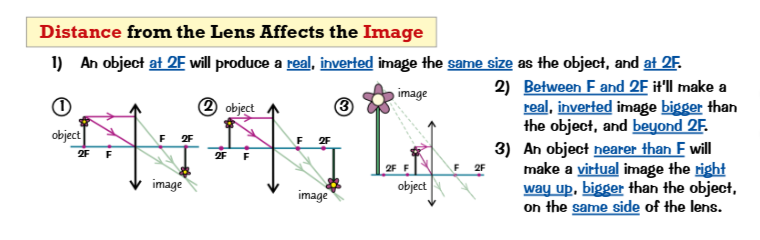
How does distance from the lens affect the image?
If the object is at 2F (twice the focal length):
The image is real
Inverted
Same size as the object
Formed at 2F on the other side
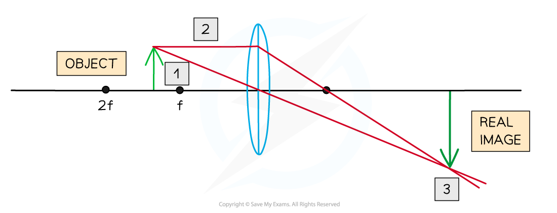
If the object is between F and 2F:
The image is real
Inverted
Magnified (larger than the object)
Formed beyond 2F
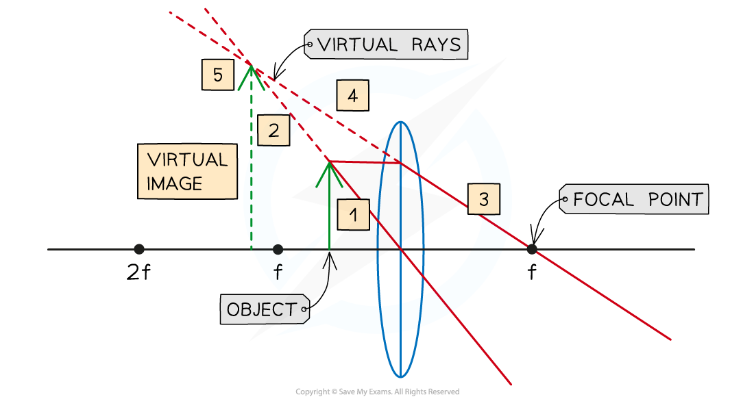
If the object is closer than F (inside the focal length):
The image is virtual
Upright
Magnified
Appears on the same side of the lens as the object
How to draw ray diagram for a concave lens?
Draw a concave lens (thin in the middle, thicker at the edges)Concave- line points inwards
Draw the principal axis through the centre of the lens
Draw the object (arrow) above the axis
Ray rules:
Draw a ray from the top of the object parallel to the principal axis
After refraction, it diverges and appears to come from the principal focus (F)
Extend this refracted ray backwards (dotted line) to the focus
Draw a ray from the top of the object through the centre of the lens
This ray continues in a straight line without bending
Image formation:
The refracted rays diverge, so extend them backwards (dotted lines)
Where the backward extensions meet, mark the top of the image
Repeat for the bottom of the object
The image is:
Virtual
Upright
Diminished (smaller than the object)
Formed on the same side of the lens as the object
Concave lens always produce a…
Virtual image. The image is the right way up, smaller that the object and on the same side of the lens as the object.
How Magnifying glasses work?
A magnifying glass uses a convex lens
The object must be placed closer than the focal length (inside F)
This produces a virtual image
Upright
Magnified (larger than object)
Appears on the same side of the lens as the object
A virtual image cannot be projected onto a screen
Because light rays do not actually meet
Magnification > 1 → image is bigger
Virtual image = no real light convergence
Works because rays are refracted and appear to diverge from a point
The visible spectrum(a range if wavelengths we perceive as different colours) is a small part of the EM spectrum -
Visible light ranges from about 400 nm (violet) to 700 nm (red)
Different wavelengths correspond to different colours
Colours of light can be mixed
Primary colours of light: red, green, blue (cannot be made by mixing)
Mixing all colours of visible light produces white light
?How do colour and transparency depend on absorbed wavelength?
Objects interact with light by absorbing, reflecting, or transmitting different wavelengths
Opaque objects do not transmit light
Opaque objects absorb some wavelengths and reflect others
The colour of an opaque object depends on the wavelengths it reflects
Example: a red object appears red because it reflects red wavelengths and absorbs others
Some colours (e.g. yellow objects) may reflect a single wavelength or a mix of primary colours (red + green)
White objects reflect all wavelengths of visible light equally
Black objects absorb all wavelengths of visible light (no reflection)
Transparent objects transmit most light
Translucent objects transmit some light but scatter it
Transparent/translucent objects may still absorb or reflect some wavelengths
The colour of transparent/translucent objects depends on transmitted and reflected wavelengths
Colour Filters
Colour filters only allow certain wavelengths of light to pass through
All other wavelengths are absorbed
A primary colour filter only transmits its own colour
White light entering a filter loses all other colours except the one transmitted
If you view a blue object through a blue filter:
It appears blue because only blue light is transmitted
If you view a red object through a blue filter:
It appears black/dark because no red light is transmitted
The final colour seen depends on which wavelengths are transmitted by both the object and the filter
All objects emit and absorb infrared (IR) radiation from their surface.
Hotter objects emit more IR radiation per second than cooler ones.
If an object is hotter than its surroundings:
It emits more IR than it absorbs
It cools down
If an object is cooler than its surroundings:
It absorbs more IR than it emits
It warms up
At constant temperature:
Emit IR radiation at the same rate they absorb IR radiation
Surface effects:
Black, matt surfaces → best emitters and absorbers
White, shiny surfaces → poor emitters and absorbers (reflect IR)
Example:
A hot drink cools because it emits more IR radiation than it absorbs.
How to investegate IR emission using a Leslie cube? RP
Cube is boiling so don’t touch
Place a Leslie cube on a heat-proof mat.
Fill it with boiling water.
Wait for it to warm up evenly.
Check all faces with a thermometer to confirm they are the same temperature.
Place an infrared detector a fixed distance (e.g. 10 cm) from one face.
Record the IR radiation detected.
Repeat for each face, keeping the distance constant.
Repeat the whole experiment for reliability.
Expected Results
Black surface → emits the most IR radiation
Matt surfaces → emit more than shiny surfaces
Shiny surface → emits the least IR radiation
Black Body
A perfect black body absorbs all radiation that hits it (no reflection or transmission) and is the best possible emitter of electromagnetic (EM) radiation.
All objects emit EM radiation due to their thermal energy store, not just infrared, but a range of wavelengths.
Intensity is the power per unit area (energy transferred per second per unit area).
As temperature increases, the intensity of all wavelengths increases, with shorter wavelengths increasing more rapidly than longer wavelengths.
The intensity and distribution of the wavelengths emitted by an object depends on the objects temperature.
The distribution of wavelengths shows how intensity is spread across different wavelengths and changes with temperature.
The peak wavelength is the wavelength with the highest intensity, and it decreases as temperature increases.
Overall, hotter objects have higher intensity and a shorter peak wavelength.
How does radiation affect the Earth’s temperature?
The Earth’s overall temperature depends on how much radiation it reflects, absorbs, and emits.
During the day, the Earth absorbs more radiation (e.g. sunlight), so local temperature increases.
At night, the Earth emits more radiation than it absorbs, so local temperature decreases.
Overall, the Earth’s temperature stays fairly constant because there is a balance between absorbed and emitted radiation.
Changes in the atmosphere can affect temperature:
If the atmosphere absorbs more radiation than it emits, the Earth’s temperature increases
This continues until absorption = emission again (new equilibrium)
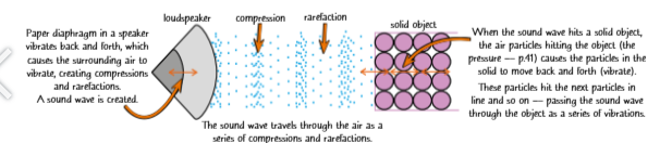
Sound Waves
Sound waves are produced by vibrating objects.
They travel as longitudinal waves, made of compressions and rarefactions through a medium.
Sound travels fastest in solids, slower in liquids, and slowest in gases.
In solids, sound is transmitted when particles vibrate and pass the vibration to neighbouring particles.
In a speaker, a vibrating diaphragm moves air particles, creating compressions and rarefactions.
When sound hits a solid, air particles transfer pressure to the solid’s particles, causing them to vibrate and pass the wave through.
Sound cannot travel in space because there are no particles in a vacuum to carry vibrations.
If the sound reaches an ear, it makes the eardrum vibrate, allowing it to be heard
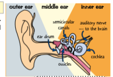
How do you hear sound?
Sound waves reaching the eardrum cause it to vibrate.
Vibrations are passed through the ossicles and then to the cochlea.
The cochlea converts vibrations into electrical signals sent to the brain, allowing us to hear.
Humans hear frequencies from 20 Hz to 20 kHz.
Different materials and systems respond to different frequency ranges.
Microphones can detect frequencies outside human hearing, but we cannot hear them directly.
Human hearing is limited by the size and structure of the eardrum and inner ear components that transfer vibrations.
Microphones work similarly:
A diaphragm vibrates when sound waves hit it
This vibration is converted into an electrical signal
How sound waves reflect and refract?
Sound waves can be reflected by hard, flat surfaces, producing echoes.
An echo is simply a reflected sound wave.
Sound waves can also refract (bend) when they pass between different media.
When sound enters a denser medium, it travels faster.
This happens because:
The frequency stays constant
The wavelength changes
So the speed must change (since speed = frequency × wavelength)
In normal conditions, refraction of sound is hard to notice because the change in direction is usually small.
Ultrasound
Electrical devices can produce electrical oscillations at different frequencies.
These oscillations can be converted into mechanical vibrations, creating sound waves.
Sound waves with frequencies above 20,000 Hz are called ultrasound.
Ultrasound is beyond the range of human hearing.
Ultrasound is widely used in many applications because it can be generated and detected by electronic devices.
How Ultrasound waves get reflected at boundaries?
When a wave passes between two different media, part of it is reflected and part is transmitted (and refracted). This is called partial reflection.
Ultrasound pulses can be directed at objects or materials.
At each boundary between different substances, some of the ultrasound is reflected back.
The time taken for the reflected waves to return can be used to calculate the distance to the boundary.
Uses of Ultrasound
Medical imaging (e.g. foetal scanning):
Ultrasound passes through the body but is partly reflected at boundaries between different tissues.
The reflected echoes are detected and timed.
A computer uses this data to create a video image of the foetus.
Ultrasound is generally considered safer than X-rays, which are definitely harmful.
Industrial imaging (flaw detection):
Ultrasound is used to detect cracks or flaws in materials like metal or wood.
Waves are normally reflected from the far side of the object.
If there is a defect, reflections return sooner than expected, revealing the flaw.
Echo sounding:
Uses high-frequency sound (including ultrasound).
Used by boats and submarines to measure water depth or detect objects underwater.
What can waves be used for?
Waves have different properties (e.g. speed) depending on the material they travel through.
When a wave reaches a boundary between materials, it can:
Be completely reflected or partially reflected (e.g. ultrasound imaging)
Be transmitted but change speed, which may cause refraction
Be absorbed
These effects also apply to different wave types, such as ultrasound waves and seismic waves (e.g. S-waves).
By studying how waves travel, reflect, and refract, scientists can investigate hidden or invisible structures that cannot be seen directly.
How earthquakes and explosions cause seismic waves?
Earthquakes produce seismic waves that travel through the Earth.
These waves are detected worldwide using seismometers.
Seismologists:
Measure the time taken for waves to reach different locations
Identify areas where waves are not detected at all
When seismic waves meet boundaries between Earth’s layers (with different properties like density):
Some waves are absorbed
Some are refracted (change direction due to speed change)
If wave speed changes gradually, the path becomes curved.
If wave speed changes suddenly, the wave path shows a sharp bend (kink).
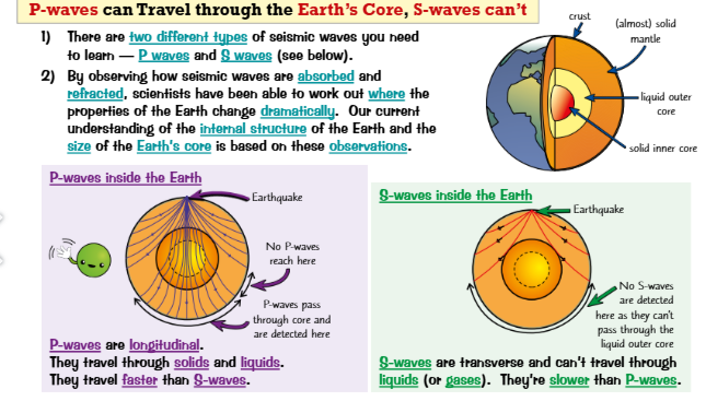
P-waves and S-waves
There are two main seismic waves: P-waves and S-waves.
By studying how waves are absorbed and refracted, scientists have worked out the internal structure of the Earth, including the core.
P-waves
Longitudinal waves
Travel through solids and liquids
Faster than S-waves
Pass through the Earth’s core, but some regions show no detection
S-waves
Transverse waves
Travel only through solids (not liquids or gases)
Slower than P-waves
Cannot pass through the liquid outer core, so they are not detected on the opposite side of the Earth