CINF Chapter 4.2
1/37
There's no tags or description
Looks like no tags are added yet.
Name | Mastery | Learn | Test | Matching | Spaced |
|---|
No study sessions yet.
38 Terms
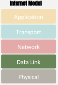
Data Link Layer
Layer 2 in the Internet Model
Responsible for moving messages from one device to another
Controls the way messages are sent on media
Relieves the upper layers from having to figure out how to access the media
Organizes physical layer bit streams into coherent messages for the network layer
Major Functions of a Data Link Layer Protocol
Media Access Control
Error Control
Message Delineation
Media Access Control
Controls which device transmits and when
Error Control
Detecting and correcting transmission errors
Message Delineation
Identifying the beginning and end of a message
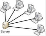
Multipoint (shared) circuits
Ensure that no two computers attempt to transmit data at the same time
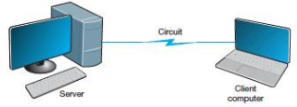
Half-duplex point-to-point circuits
Computers tale turns
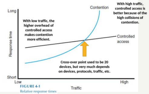
Two approaches to control
Contention access
Controlled access
Contention Acess
Transmit whenever circuit is available with no centralized control
Common in Ethernet LANs
When devices transmit at the same time, a collision occurs
Some techniques to avoid collision
Transmission detection and random delays
Controlled Access
Common in wireless LANs: Acts like a spot light
Access Request
Each device must get “permission” to transmit, similar to raising a hand
Polling
Server (periodically) polls the client if it has data to send
Roll call polling
Hub polling/token passing
Media Access Control Diagram
Error Control
Network errors
Types
Corrupted data
Lost data
Networks should be designed with:
Error prevention
Error detection
Error correction
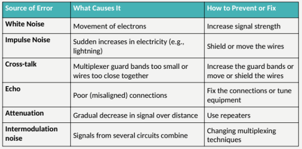
Sources of Network Errors
Line noise and distortion
Major reason for errors and caused by several sources
More likely on electrical media
Undesirable electrical signal
Degrades performance of a circuit
Manifestation
Extra bits
“Flipped” bits
Missing bits
Error Prevention
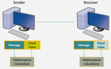
Error Detection
Receivers need to know when the data transmitted is not corrected
Solution: send extra data with each message
Add “check value” (error detection value) to message

Error Detection 2
Both sender and receiver calculate check value
Receiver tests whether the check values match
Three Error Detection Methods
Parity
Checksums
Cyclical Redundancy Check (CRC)
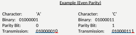
Parity Check
A single parity bit: 1-bit check value
Based on the number of 1’st in the message
Even parity: number of 1’s remains even
Odd parity: number of 1’s remains odd
Parity Check Example
Detect single error? Yes
Two? No
It does not know what the error is
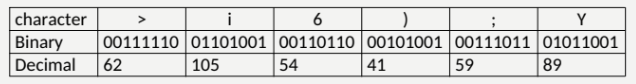
Checksum
1-byte (typically) check value
Checksum algorithms vary in the creation of check values: Sum up
Method:
Add decimals values of each character in the message
Divide the sum by 255
The remainder is the checksum value
Checksum Example
Sum of decimal = 410
410/225 = 1 + 155/255
155 = 10011011
Easy to compute, but fragile
but error are frequently undetected
Cyclic Redundancy Check (CRC)
-Treats messages as a single binary number (p)
-Divides by a present number (the generator, G)
-Uses remainder as the check vale (R)
Generator is chosen so that remainder is the correct number of bits
Most powerful and most common
Detects100% of error if number of error <= size of R.
Error Correction Techniques
Retransmission (or backward error correction)
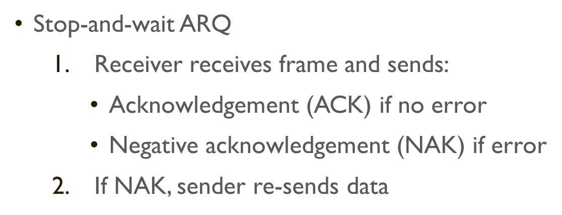
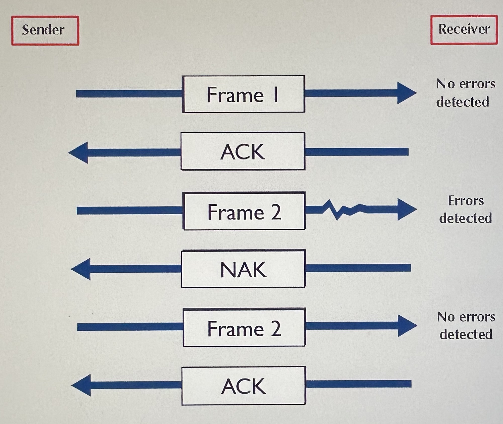
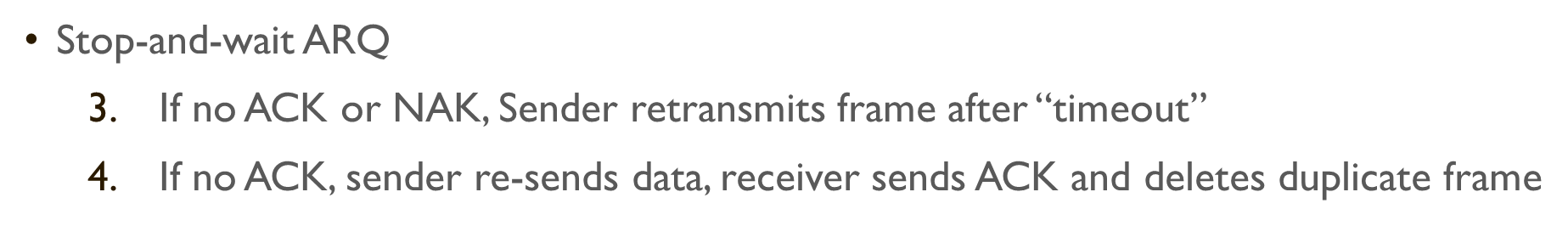
Automatic Repeat reQuest (ARQ)
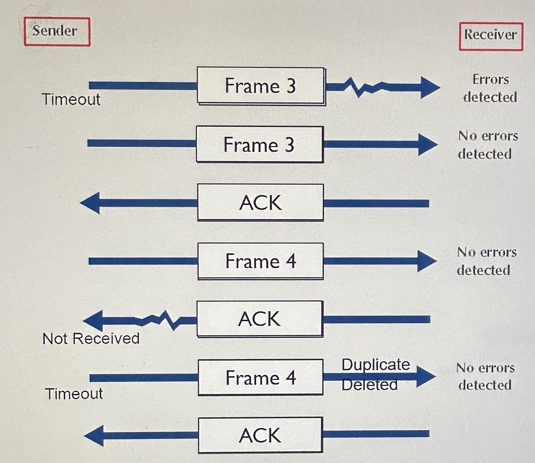
Stop-and-wait ARQ
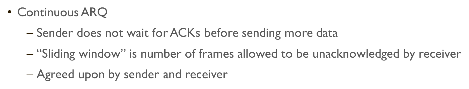
Continuous ARQ
Forward error correction
Receiving device can correct messages without retransmission
Error Correction
Error Correction 2
Error Correction 3
Forward Error Correction
Includes a certain level of redundancy in transmitted data so that receiving device can correct errors
Does not require retransmission
Used only when retransmission is impossible, very costly, or time consuming (e.g., satellite connections)
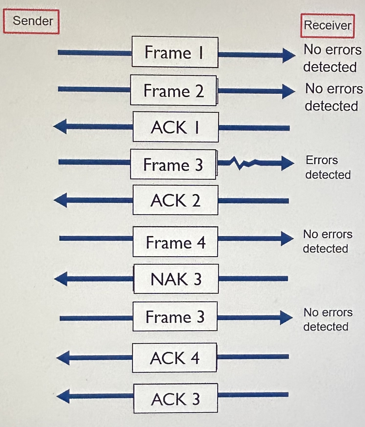
Error Correction - Hamming Code
Each data bit figures into three EVEN parity bit calculations
If any one bit (parity or data) changes → change in data bit can be detected and corrected
only works for one bit error
Error control in practice
On wired connections, errors are quite rare
Most data link layer software today does not correct errors, only detect them and discard frames with errors
Error correction must then be done at a higher layer (Transport)
2 types of Classification
Asynchronous transmission
Synchronous transmission
Protocols differ by
Message delineation
Frame length
Frame field structure
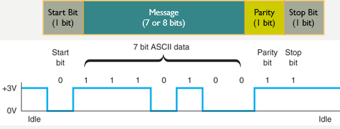
Asynchronous serial transmission (async)
old protocol (e.g., used in teletype)
transmits one character at a time
delineation indicated by start and stop bits
Synchronous transmission
Data sent in a large block called a frame
Includes addressing information
Includes synchronization characters to let the receiver know when data transmission begins
Example protocols: SDLC, HDLC, Ethernet, PPP
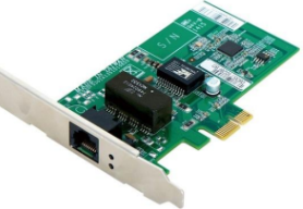
Ethernet
IEEE 802.3 standard and Ethernet II
Mostly widely used LAN protocol, developed jointly by Digital, Intel, and Xerox, now an IEEE standard
Most widely used LAN protocol
Uses contention media access control
Ethernet II Frame
interframe gap (12 bytes)
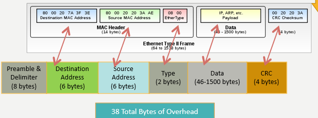
MAC Address
Also called physical address
Used to get datagram from one interface to another physically-connected interface (same network)
48-bit (6 byte) MAC address
ex: 8C-AE-4C-FA-63-9E
burned in the adapter ROM
6 groups of two hexadecimal digits