Fundamentals of Electricity (FAA General Exam Practice)
1/120
Earn XP
Description and Tags
FAA Fundamentals of Electricity and Electronics questions directly from the 2024 General written test guide.
Name | Mastery | Learn | Test | Matching | Spaced |
|---|
No study sessions yet.
121 Terms
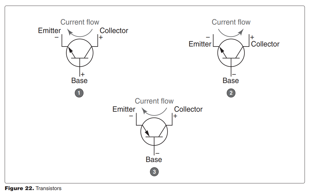
8078. (Refer to Figure 22.) Which illustration is correct concerning bias application and current (positive charge) flow?
A—1.
B—2.
C—3.
[a] In 1, the base of this N-P-N transistor is positive with respect to the emitter (the emitter-base junction is forward biased). Base-emitter current flows and therefore collector emitter current flows as is shown by the current-flow arrow.
In 2, the base and emitter of this N-P-N transistor have the same polarity and no emitter-base current flows. There is no flow between the emitter and the collector.
In 3, the base and emitter of this P-N-P transistor have the same polarity, and no emitter-base current flows. There is no flow between the emitter and the collector. (AM.I.A.K1) — FAA-H-8083-30
8004-1. What factors strengthen a coil inductor?
A—Limiting and separating the coils.
B—Adding and separating the coils.
C—Adding coils close together.
[c] As more loops are added close together, the strength of the magnetic field increases. Many loops close together will result in a strong electromagnet. (AM.I.A.K2) — FAAH-8083-30
8052. Through which material will magnetic lines of force pass the most readily?
A—Copper.
B—Iron.
C—Aluminum
[b] The permeability of a material is a measure of the ease with which lines of magnetic force can pass through it. Iron has the highest permeability of all the metals listed in this question. (AM.I.A.K2) — FAA-H-8083-30
8001. The working voltage of a capacitor in an AC circuit should be
A—equal to the highest applied voltage.
B—at least 20 percent greater than the highest applied voltage.
C—at least 50 percent greater than the highest applied voltage.
[c] The working voltage of a capacitor is the highest voltage that can be steadily applied to it without the danger of the dielectric breaking down. The working voltage depends upon the material used as the dielectric and on its thickness. A capacitor used in an AC circuit should have a working voltage at least 50 percent greater than the highest voltage that will be applied to it. (AM.I.A.K3) — FAA-H-8083-30
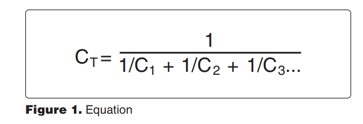
8006. (Refer to Figure 1.) When different rated capacitors are connected in series in a circuit, the total capacitance is
A—less than the capacitance of the lowest rated capacitor.
B—greater than the capacitance of the highest rated capacitor.
C—equal to the sum of all the capacitances
[a] When capacitors of different values are connected in series, the total capacitance is less than that of the lowest rated capacitor. (AM.I.A.K3) — FAA-H-8083-30
8006-1. Capacitors are sometimes used in DC circuits to
A—counteract inductive reactance at specific locations.
B—smooth out slight pulsations in current/voltage.
C—assist in stepping voltage and current up and/or down
[b] Capacitors store electrical charges and are sometimes used in DC circuits to smooth out slight pulsations in current or voltage. Capacitors accept electrons when there is an excess and release them back into the circuit when the values decrease. (AM.I.A.K3) — FAA-H-8083-30
8008. The amount of electricity a capacitor can store is directly proportional to the
A—distance between the plates and inversely proportional to the plate area.
B—plate area and is not affected by the distance between the plates.
C—plate area and inversely proportional to the distance between the plates
[c] Three factors affect the amount of electricity a capacitor can store:
1. The area of the plates. The larger the plate area, the greater the capacity.
2. The thickness of the dielectric (the distance between the plates). The closer the plates are together, the stronger the electrical field will be and the greater the capacity.
3. The material from which the dielectric is made (its dielectric constant). The higher the dielectric constant, the greater the capacity. (AM.I.A.K3) — FAA-H-8083-30
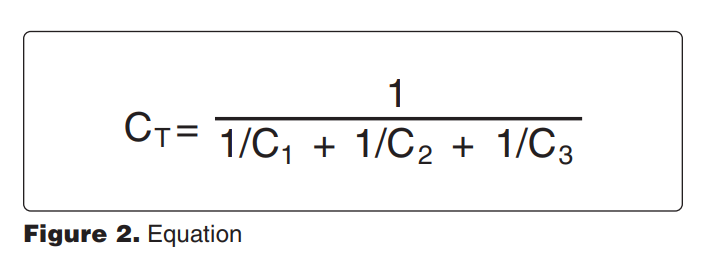
8009. (Refer to Figure 2.) What is the total capacitance of a certain circuit containing three capacitors with capacitances of .02 microfarad, .05 microfarad, and .10 microfarad, respectively?
A—.170 μF.
B—0.125 pF.
C—.0125 μF
[c] When a 0.02-microfarad, a 0.05-microfarad, and a 0.10-microfarad capacitor are connected in series, the total capacitance is 0.0125 microfarad. µF (AM.I.A.K3) — FAA-H-8083-30
8009-1. What is the total capacitance of a circuit containing three capacitors in parallel with capacitances of .02 microfarad, .05 microfarad, and .10 microfarad, respectively?
A—.170 μF.
B—0.125 μF.
C—.0125 μF
[a] Use the formula CT = C1 + C2 + C3. When capacitors are connected together in parallel, the plate area of all the capacitors add together and the total capacitance is the sum of the individual capacitances.
.02 + .05 + .10 = .170 µF
(AM.I.A.K3) — FAA-H-8083-30
8014. What is the total capacitance of a certain circuit containing three capacitors with capacitances of .25 microfarad, .03 microfarad, and .12 microfarad, respectively?
(Note: CT = C1 + C2 + C3)
A—.4 μF.
B—.04 pF.
C—.04 μF.
[a] When three capacitors are connected in parallel, their total capacitance is the sum of the individual capacitances.
CT = C1 + C2 + C3
= 0.25 + 0.03 = 0.12
= 0.4 μF
(AM.I.A.K3) — FAA-H-8083-30
8029-2. What does the letter Q symbolize when measuring electrical charge?
A—Farad.
B—Electron.
C—Coulomb.
[c] The general formula for capacitance in terms of charge and voltage is C = Q/E, where:
C = Capacitance measured in farads
E = Applied voltage measured in volts
Q = Charge measured in coulombs
(AM.I.A.K3) — FAA-H-8083-30
8005. An increase in which of the following factors will cause an increase in the inductive reactance of a circuit?
A—Inductance and frequency.
B—Resistance and voltage.
C—Resistance and capacitive reactance
[a] The inductive reactance (XL) in an AC circuit is increased when either the frequency of the alternating current or the inductance of the circuit is increased.
Resistance, voltage, or capacitive reactance have no effect on the inductive reactance of a circuit. The formula for inductive reactance is:
XL = 2πfL
(AM.I.A.K4) — FAA-H-8083-30
8011. When different rated capacitors are connected in parallel in a circuit, the total capacitance is
(Note: CT = C1 + C2 + C3 . . .)
A—less than the capacitance of the lowest rated capacitor.
B—equal to the capacitance of the highest rated capacitor.
C—equal to the sum of all the capacitances
[c] When capacitors are connected in parallel, the effective area of the plates combine, and the total capacitance is the sum of the individual capacitances. (AM.I.A.K4) — FAA-H-8083-30
8012. When inductors are connected in series in a circuit, the total inductance (where the magnetic fields of each inductor do not affect the others) is
(Note: LT = L1 + L2 + L3 . . .)
A—less than the inductance of the lowest rated inductor.
B—equal to the inductance of the highest rated inductor.
C—equal to the sum of the individual inductances.
[c] When several inductors are connected together in such a way that there is no inductive coupling, the total inductance is the sum of the individual inductances. (AM.I.A.K4) — FAA-H-8083-30

8013. (Refer to Figure 3.) When more than two inductors of different inductances are connected in parallel in a circuit, the total inductance is
A—less than the inductance of the lowest rated inductor.
B—equal to the inductance of the highest rated inductor.
C—equal to the sum of the individual inductances.
[a] When two or more inductors having different inductances are connected in parallel, the total inductance is less than the inductance of the lowest rated inductor. (AM.I.A.K4) — FAA-H-8083-30
8041. Transfer of electric energy from one circuit to another without the aid of electrical connections
A—is called induction.
B—is called capacitance.
C—can cause excessive arcing and heat, and as a result is practical for use only with low voltages/amperages.
[a] The continually changing current in an AC circuit causes a changing magnetic field to cut across conductors in an adjacent circuit. When the changing field cuts across a conductor, it induces a voltage in it. Induction allows electrical energy to be transferred from one circuit to another without the aid of electrical connections. (AM.I.A.K4) — FAA-H-8083-30
8002. The term that describes the combined resistive forces in an AC circuit is
A—resistance.
B—reactance.
C—impedance
[c] Impedence (Z) is the vector sum of the resistance and the total reactance in a circuit. It is expressed in ohms, and found using the formula:
There are three types of resistive forces in an AC circuit: inductive reactance, which causes the current to lag the voltage; capacitive reactance, which causes the current to lead the voltage; and resistance, which allows the current and voltage to remain in phase.
Inductive and capacitive reactance are 180° out of phase and cancel each other. (AM.I.A.K5) — FAA-H8083-30
8002-1. What is the opposition to the flow of AC produced by an electromagnetic field (EMF) with generated back voltage called?
A—Inductive reactance.
B—Capacitive reactance.
C—Mutual inductance.
[a] Alternating current is in a constant state of change; EMF causes continuously inducted voltage opposition to the current in the circuit. This opposition is called inductive reactance (XL), and is measured in ohms just as resistance is measured. Inductance is the property of a circuit to oppose any change in current and is measured in henries. Inductive reactance is a measure of how much the countering EMF in the circuit will oppose current variations. (AM.I.A.K5) — FAA-H-8083-30
8004. The opposition offered by a coil to the flow of alternating current (ignoring resistance) is called
A—impedance.
B—reluctance.
C—inductive reactance.
[c] When alternating current flows in a coil of wire, the changing lines of flux cutting across the turns of wire in the coil induce a voltage in it. The polarity of this voltage (the counter EMF) is opposite to the polarity of the voltage that caused it. The counter EMF decreases the total voltage across the coil, and this decreases the current flowing through it. This opposition to the flow of alternating current is called inductive reactance (XL) and is measured in ohms. It opposes the flow of current, but it does not cause heat nor use any power. (AM.I.A.K5) — FAA-H-8083-30
8007. In an AC circuit, the effective voltage is
A—equal to the maximum instantaneous voltage.
B—greater than the maximum instantaneous voltage.
C—less than the maximum instantaneous voltage.
[c] The effective voltage of sine wave alternating current is 0.707 time its peak voltage. The effective voltage, also called the root mean square (rms) voltage, is the voltage measured by most of the AC voltmeters. Peak voltage is measured with a special peak voltmeter or an oscilloscope. (AM.I.A.K5) — FAA-H-8083-30
8010. Unless otherwise specified, any values given for current or voltage in an AC circuit are assumed to be
A—instantaneous values.
B—effective values.
C—maximum values.
[b] Almost all measuring instruments used for electrical system servicing measure the effective rms values of alternating current. Unless peak values, peak-to-peak values, or average values are specifically called out, effective rms values are assumed. (AM.I.A.K5) — FAA-H-8083-30
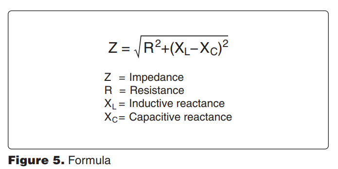
8024. (Refer to Figure 5.) What is the impedance of an AC-series circuit consisting of an inductor with a reactance of 10 ohms, a capacitor with a reactance of 4 ohms, and a resistor with a resistance of 8 ohms?
A—22 ohms.
B—5.29 ohms.
C—10 ohms
[c] The total reactance in this circuit is the difference between the inductive reactance and the capacitive reactance. Total reactance is 10 – 4 = 6 ohms. The impedance is the square root of the resistance squared plus the reactance squared. This is the square root of 64 plus 36, or the square root of 100. The circuit impedance is 10 ohms. (AM.I.A.K5) — FAA-H-8083-30
8039. When referencing resistance in a parallel DC circuit, which of the following statements is true?
A—The current is equal in all portions of the circuit.
B—The total current is equal to the sum of the currents through the individual branches of the circuit.
C—The current in amperes can be found by dividing the source voltage in volts by the sum of the resistors in ohms
[b] According to Kirchhoff’s current law, the current flowing in a parallel circuit is equal to the sum of the currents flowing through each of the individual branches of the circuit. (AM.I.A.K7b) — FAA-H-8083-30
8009-2. Convert farads to microfarads by
A—multiplying farads by 10 to the power of 6
B—multiplying picofarads by 10 to the power of 6
C—multiplying microfarads by 10 to the power of 6
[a] One farad is equal to 106 microfarads. Example: 2 farads is equal to 2 × 10⁶ (2,000,000) microfarads. (AM.I.A.K8) — FAA-H-8083-30
8009-3. Convert farads to picofarads by:
A—multiplying farads by 10 to the power of 12
B—multiplying microfarads by 10 to the power of -12
C—multiplying picofarads by 10 to the power of 12
[a] One farad is equal to 1012 picofarads. Example: 2 farads is equal to 2 × 10¹² (2,000,000,000) picofarads. (AM.I.A.K8) — FAA-H-8083-30
8015. Which requires the most electrical power during operation?
(Note: 1 horsepower = 746 watts)
A—A 12-volt motor requiring 8 amperes.
B—Four 30-watt lamps in a 12-volt parallel circuit.
C—Two lights requiring 3 amperes each in a 24-volt parallel system.
[c] The 12-volt motor requires 96 watts of power. The four 30-watt lamps require 120 watts of power. The two 24-volt, 3-amp lights require 144 watts of power. (AM.I.A.K8) — FAA-H-8083-30
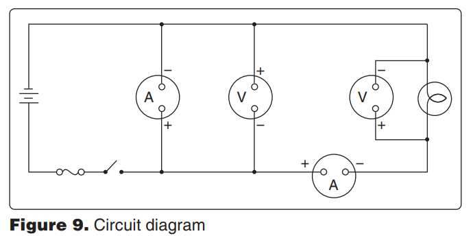
8028. (Refer to Figure 9.) How many instruments (voltmeters and ammeters) are installed correctly?
A—Three.
B—One.
C—Two.
[c] The first ammeter is installed across the voltage. This is wrong; the ammeter will burn out. The first voltmeter will measure the source voltage (the voltage of the battery), but its polarity is wrong. It will read backward. The voltmeter across the light bulb is installed correctly. The ammeter in series with the light bulb and the battery is correct. It will read the current flowing through the light bulb. (AM.I.A.K8) — FAA-H-8083-30
8029. The correct way to connect a test voltmeter in a circuit is
A—in series with a unit.
B—between the source voltage and the load.
C—in parallel with a unit.
[c] A voltmeter must always be connected in a circuit in parallel with the unit whose voltage is to be measured. (AM.I.A.K8) — FAA-H-8083-30
8029-1. What will a voltmeter read if properly connected across a closed switch in a circuit with electrical power on?
A—Voltage drop in the component(s) the switch is connected to.
B—System voltage.
C—Zero voltage.
[c] When a voltmeter is connected across a closed switch in perfect condition or a good fuse, it will read zero voltage. A voltage drop of up to 0.2 volts is acceptable with maximum circuit current flow through the switch. (AM.I.A.K8) — FAA-H-8083-30, AC43.13-1B Ch.11
8030. Which term means .001 ampere?
A—Microampere.
B—Kiloampere.
C—Milliampere.
[c] The metric prefix “milli-” means one thousandth. 0.001 ampere is one milliampere. (AM.I.A.K8) — FAA-H-8083-30
8033. .002 kV equals
A—20 volts.
B—2.0 volts.
C—.2 volt.
[b] One kilovolt (kV) is 1,000 volts. Two thousandths (.002) of a kilovolt is equal to 2.0 volts. (AM.I.A.K8) — FAA-H-8083-30
8037-1. What is the basic unit of electrical quantity?
A—Electromotive force.
B—Ampere.
C—Coulomb.
[c] The coulomb is the basic unit of electrical quantity. One coulomb is equal to 6.28 × 10¹⁸ electrons. (AM.I.A.K8) — FAA-H-8083-30
8020. The potential difference between two conductors which are insulated from each other is measured in
A—volts.
B—amperes.
C—coulombs.
[a] The potential difference between two conductors is a measure of the electrical pressure difference between the conductors. Electrical pressure is measured in volts. (AM.I.A.K9) — FAA-H-8083-30
8021. A 24-volt source is required to furnish 48 watts to a parallel circuit consisting of four resistors of equal value. What is the voltage drop across each resistor?
A—12 volts.
B—6 volts.
C—24 volts.
[c] Since the resistors are all in parallel across the 24-volt power source, each resistor has the entire 24 volts dropped across it. (AM.I.A.K9) — FAA-H-8083-30
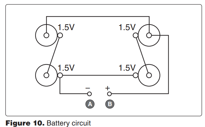
8034. (Refer to Figure 10.) What is the measured voltage of the series-parallel circuit between terminals A and B?
A—1.5 volts.
B—3.0 volts.
C—4.5 volts.
[b] The two batteries on the left side are connected in series and the two batteries on the right side are connected in series. The two pairs of batteries are connected in parallel. The series connections between terminals A and B give this circuit a voltage of 3.0 volts. (AM.I.A.K9) — FAA-H8083-30

8045. (Refer to Figure 11.) Find the voltage across the 8-ohm resistor.
A—8 volts.
B—20.4 volts.
C—24 volts.
[c] The 8-ohm resistor, R1, is across the full 24 volts of the battery. (AM.I.A.K9) — FAA-H-8083-30
8055. The voltage drop in a circuit of known resistance is dependent on
A—the voltage of the circuit.
B—only the resistance of the conductor and does not change with a change in either voltage or amperage.
C—the amperage of the circuit.
[c] The voltage drop across a circuit is determined by two things: the resistance of the circuit and the amount of current flowing through it (the amperage). In this question, the resistance of the circuit is fixed; therefore, the voltage drop is determined by the amperage in the circuit. (AM.I.A.K9) — AC 43.13-1B
8018. How many amperes will a 28-volt generator be required to supply to a circuit containing five lamps in parallel, three of which have a resistance of 6 ohms each and two of which have a resistance of 5 ohms each?
A—1.11 amperes.
B—1 ampere.
C—25.23 amperes.
[c] A current of 4.67 amps flows through each of the three six-ohm lamps. And a current of 5.6 amps flows through each of the 5-ohm lamps. Since all of these lamps are in parallel, the total current is the sum of the currents flowing through each lamp. The total current is 25.21 amps. (AM.I.A.K10) — FAA-H-8083-30
8020-1. Which effect does not apply to the movement of electrons flowing in a conductor?
A—Magnetic energy.
B—Thermal energy.
C—Static energy.
[c] Current flowing through a conductor produces a magnetic field and also dissipates thermal energy. (AM.I.A.K10) — FAA-H-8083-30
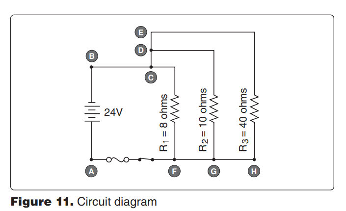
8044. (Refer to Figure 11.) Find the total current flowing in the wire between points C and D.
A—6.0 amperes.
B—2.4 amperes.
C—3.0 amperes.
[c] The total resistance between points D–E and G–H is 8 ohms. This is the resistance of resistors R2 and R3 in parallel.
R2–3 = (10 × 40) | (10 + 40)
= 400 | 50
= 8Ω
There is a voltage of 24 volts across these two parallel resistors, so the current through the line between C and D is three amps.
I = E | R
= 24 | 8
= 3 amps
(AM.I.A.K10) — FAA-H-8083-30
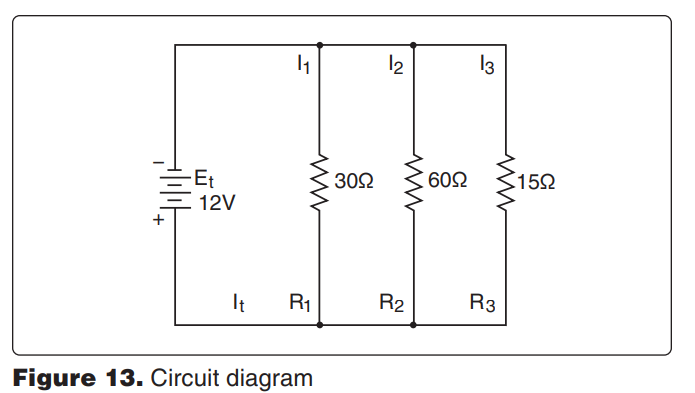
8049. (Refer to Figure 13.) Determine the total current flow in the circuit.
A—0.2 ampere.
B—1.4 amperes.
C—0.8 ampere.
[b] The total current flowing in this circuit is 1.4 amps. (AM.I.A.K10) — FAA-H-8083-30
8049-1. In a parallel circuit with three 6-ohm resistors across a 12-volt battery, what is the total current (It) value in the circuit?
A—2 amps.
B—6 amps.
C—12 amps.
[b] The total resistance of this circuit is 2 ohms. The total current flowing in this circuit is 6 amps. (AM.I.A.K10) — FAA-H-8083-30
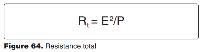
8035. (Refer to Figure 64.) A 24-volt source is required to furnish 48 watts to a parallel circuit consisting of two resistors of equal value. What is the value of each resistor?
A—24 ohms.
B—12 ohms.
C—6 ohms.
[a] To solve this problem, first find the total resistance of the circuit. RT = E2 ÷ P
= 242 ÷ 48
= 12Ω
There are two resistors of equal value in parallel that provide this resistance, therefore each resistor must have a resistance of twice this value, or 24 ohms. (AM.I.A.K11) — FAA-H-8083-30
8038. What is the operating resistance of a 30-watt light bulb designed for a 28-volt system?
A—1.07 ohms.
B—26 ohms.
C—0.93 ohm.
[b] A 30-watt light bulb operating in a 28-volt electrical system has a hot resistance (operating resistance) of 26.13 ohms.
(AM.I.A.K11) — FAA-H-8083-30
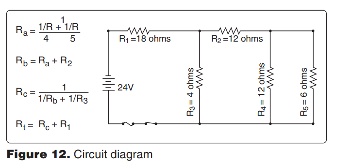
8046. (Refer to Figure 12.) Find the total resistance of the circuit.
A—16 ohms.
B—2.6 ohms.
C—21.2 ohms
[c] 21.2Ω
(AM.I.A.K11) — FAA-H-8083-30
8047. Which is correct in reference to electrical resistance?
A—Two electrical devices will have the same combined resistance if they are connected in series as they will have if connected in parallel.
B—If one of three bulbs in a parallel lighting circuit is removed, the total resistance of the circuit will become greater.
C—An electrical device that has a high resistance will use more power than one with a low resistance with the same applied voltage.
[b] In a parallel electrical circuit, each bulb provides a path for current to flow. The more paths there are, the less the circuit resistance will be. When one bulb is removed, the circuit resistance increases. (AM.I.A.K11) — FAA-H8083-30
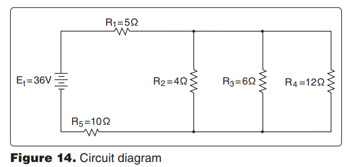
8050. (Refer to Figure 14.) The total resistance of the circuit is
A—25 ohms.
B—35 ohms.
C—17 ohms
[c] 17Ω (AM.I.A.K11) — FAA-H-8083-30
8051. Which of these will cause the resistance of a conductor to decrease?
A—Decrease the length or the cross-sectional area.
B—Decrease the length or increase the cross-sectional area.
C—Increase the length or decrease the cross-sectional area.
[b] The resistance of a conductor varies directly as its length, inversely as its cross-sectional area, and directly with the resistivity of its material. Either decreasing the length or increasing the cross-sectional area of a conductor will cause its resistance to decrease. (AM.I.A.K11) — FAAH-8083-30

8053. (Refer to Figure 64.) A 48-volt source is required to furnish 192 watts to a parallel circuit consisting of three resistors of equal value. What is the value of each resistor?
A—36 ohms.
B—4 ohms.
C—12 ohms.
[a] Since three resistors in parallel give 12 ohms, each resistor must have a resistance three times this value. (AM.I.A.K11) — FAA-H-8083-30
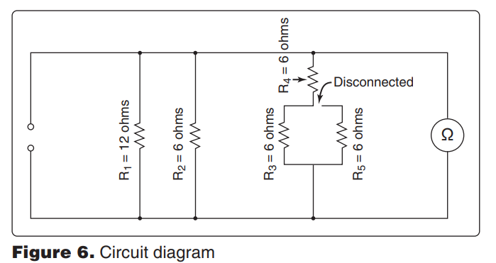
8025. (Refer to Figure 6.) If resistor R5 is disconnected at the junction of R4 and R3 as shown, what will the ohmmeter read?
A—2.76 ohms.
B—3 ohms.
C—12 ohms.
[b] 3Ω
(AM.I.A.K11d) — FAA-H-8083-30
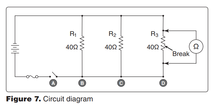
8026. (Refer to Figure 7.) If resistor R3 is disconnected at terminal D, what will the ohmmeter read?
A—Infinite resistance.
B—10 ohms.
C—20 ohms.
[a] When resistor R3 is disconnected at terminal D, it is isolated from the rest of the circuit, and the ohmmeter will read only the resistance of R3. Because R3 is open (it has a break in it), its resistance is infinite. (AM.I.A.K11d) — FAA-H-8083-30
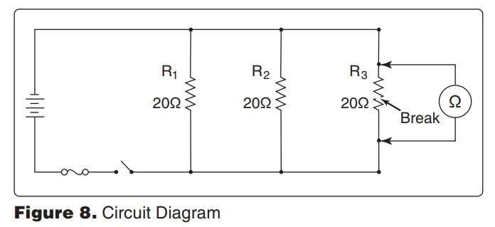
8027. (Refer to Figure 8.) With an ohmmeter connected into the circuit as shown, what will the ohmmeter read?
A—20 ohms.
B—Infinite resistance.
C—10 ohms
[c] The ohmmeter will read the resistance of R1 and R2 in parallel; this is 10 ohms. The open circuit (break) in resistor R3 gives it an infinite resistance, and it does not affect the reading of the ohmmeter. (AM.I.A.K11d) — FAA-H-8083-30
8016. How much power must a 24-volt generator furnish to a system which contains the following loads?
Unit Rating
One motor (75 percent efficient)............................1/5 hp
Three position lights ................................. 20 watts each
One heating element .............................................5 amp
One anticollision light ............................................3 amp
(Note: 1 horsepower = 746 watts)
A—402 watts.
B—385 watts.
C—450 watts
[c] The motor is 1/5 hp, therefore 746 watts (1 hp) ÷ 5 = 149 watts. This is the output of the engine. It takes more energy to produce 149 watts; find this with the efficiency rating: 149/X = 75/100; X = 199. Therefore, the 1/5 hp motor that is 75 percent efficient requires 199 watts. The three position lights require a total of 60 watts. The heating element requires 120 watts. The anticollision light requires 72 watts. The total power the generator must produce is 451 watts. (AM.I.A.K12) — FAA-H-8083-30
8017. A 12-volt electric motor has 1,000 watts input and 1 horsepower output. Maintaining the same efficiency, how much input power will a 24-volt, 1-horsepower electric motor require? (Note: 1 horsepower = 746 watts)
A—1,000 watts.
B—2,000 watts.
C—500 watts.
[a] The power produced by an electric motor is the product of its voltage and its current. A 12-volt motor will require 83.3 amps of current for its 1,000 watts of input power to produce 746 watts (1 horsepower) of output power. A 24-volt motor operating at the same efficiency will also require 1,000 watts of input power for its 746 watts of output power, but it will need only 41.7 amps of current. (AM.I.A.K12) — FAA-H-8083-30
8019. A 24-volt, 1-horsepower DC electric motor that is 80 percent efficient requires 932.5 watts. How much power will a 12-volt, 1-horsepower DC electric motor that is 75 percent efficient require? (Note: 1 horsepower = 746 watts)
A—932.5 watts.
B—1,305.5 watts.
C—994.6 watts.
[c] When we know the horsepower output and the efficiency of an electric motor, the voltage does not enter into the computation. To find the number of watts required, divide the wattage for the total horsepower by the decimal equivalent of the efficiency.
746 ÷ 0.75 = 994.6 watts
(AM.I.A.K12) — FAA-H-8083-30
8022. When calculating power in a reactive or inductive AC circuit, the true power is
A—more than the apparent power.
B—less than the apparent power in a reactive circuit and more than the apparent power in an inductive circuit.
C—less than the apparent power
[c] True power in an AC circuit is the product of the circuit voltage and only that part of the current in phase with the voltage. Apparent power is the circuit voltage multiplied by all of the current. True power is always less than the apparent power in a reactive circuit which is any AC circuit containing either inductance or capacitance. (AM.I.A.K12) — FAA-H-8083-30
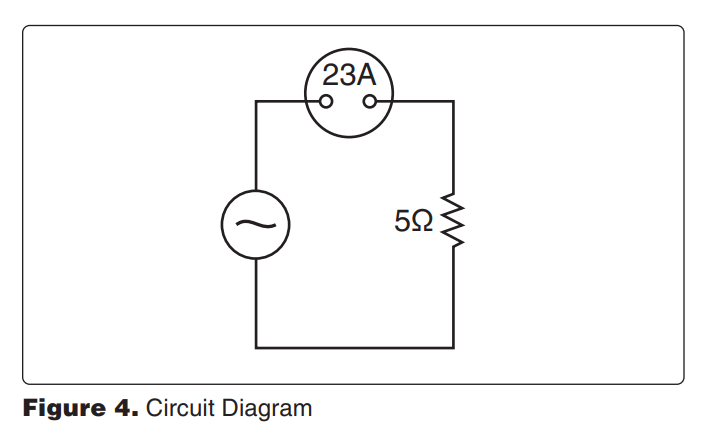
8023. (Refer to Figure 4.) How much power is being furnished to the circuit?
A—575 watts.
B—2,875 watts.
C—2,645 watts.
[c] This is a resistive circuit. The power is the product of the square of the current times the resistance.
P = I 2 × R = 232 × 5 = 2,645 watts
(AM.I.A.K12) — FAA-H-8083-30
8036. Which requires the most electrical power? (Note: 1 horsepower = 746 watts)
A—A 1/5-horsepower, 24-volt motor which is 75 percent efficient.
B—Four 30-watt lamps arranged in a 12-volt parallel circuit.
C—A 24-volt anticollision light circuit consisting of two light assemblies which require 3 amperes each during operation
[a] The 1/5-horsepower motor operating at 75 percent efficiency uses 198.93 watts of power. The four 30-watt lamps use 120 watts of power. The anticollision light circuit uses 144 watts of power. (AM.I.A.K12) — FAA-H-8083-30
8037. What unit is used to express electrical power?
A—Volt.
B—Watt.
C—Ampere.
[b] A watt is a measure of electrical power. A volt is a measure of electrical pressure. An ampere is a measure of electrical current flow. (AM.I.A.K12) — FAA-H-8083-30
8048. What happens to the current in a voltage step-up transformer with a ratio of 1 to 4?
A—The current is stepped down by a 1 to 4 ratio.
B—The current is stepped up by a 1 to 4 ratio.
C—The current does not change.
[a] The power (voltage times current) in the secondary of a transformer is equal to the power in the primary. When the voltage in the secondary is four times that in the primary, the current in the secondary is one fourth of that in the primary. (AM.I.A.K12) — FAA-H-8083-30
8032. A 14-ohm resistor is to be installed in a series circuit carrying .05 ampere. How much power will the resistor be required to dissipate?
A—At least .70 milliwatt.
B—At least 35 milliwatts.
C—Less than .035 watt.
[b] Power dissipated in a resistor is found by multiplying its resistance by the square of the current.
P = I 2 × R = 0.052 × 14 = 0.035 watts
0.035 watts is 35 milliwatts.
(AM.I.A.K13) — FAA-H-8083-30
8042. If three resistors of 3 ohms, 5 ohms, and 22 ohms are connected in series in a 28-volt circuit, how much current will flow through the 3-ohm resistor?
A—9.3 amperes.
B—1.05 amperes.
C—0.93 ampere.
[c] In a series circuit, the total resistance is the sum of the individual resistances. In this circuit, the total resistance is 30 ohms. All of the current flows through each resistor. Therefore, the current through each resistor is 0.93 amp. (AM.I.A.K13) — FAA-H-8083-30
8043. A circuit has an applied voltage of 30 volts and a load consisting of a 10-ohm resistor in series with a 20-ohm resistor. What is the voltage drop across the 10-ohm resistor?
A—10 volts.
B—20 volts.
C—30 volts.
[a] In a series circuit, the voltage drop across each resistor is determined by its resistance. In this circuit, the total resistance is 30 ohms and the total voltage is 30 volts. One amp of current flows through each resistor and this gives a 10-volt drop across the 10-ohm resistor.
E = I × R
= 1 × 10
= 10 volts
(AM.I.A.K13) — FAA-H-8083-30
8031. A cabin entry light of 10 watts and a dome light of 20 watts are connected in parallel to a 30-volt source. If the voltage across the 10-watt light is measured, it will be
A—equal to the voltage across the 20-watt light.
B—half the voltage across the 20-watt light.
C—one-third of the input voltage.
[a] When lights are connected in parallel across a voltage source, the voltage across each of the lights will be the same as the voltage of the source. (AM.I.A.K14) — FAAH-8083-30
8045-1. In a parallel circuit with four 6-ohm resistors across a 24-volt battery, what is the total voltage across resistor-three (VR3) in the circuit?
A—6 volts.
B—18 volts.
C—24 volts.
[c] In a parallel circuit the source or battery voltage is applied to each of the individual resistors. (AM.I.A.K14) — FAAH-8083-30
8054. Which is correct concerning a parallel circuit?
A—Total resistance will be smaller than the smallest resistor.
B—Total resistance will decrease when one of the resistances is removed.
C—Total voltage drop is the same as the total resistance.
[a] In a parallel circuit each resistor forms a path for the current to follow and the total resistance is always smaller than that of the smallest resistor. (AM.I.A.K14) — FAA-H-8083-30
8045-2. If each cell, connected in series, equals 2 volts, how would a 12-cell lead acid battery be rated?
A—24 volts.
B—12 volts.
C—6 volts
[a] The voltage of a battery is determined by the number of cells connected in series to form the battery. Although the voltage of one lead-acid cell just removed from a charger is approximately 2.2 volts, a lead-acid cell is normally rated at approximately 2 volts. A battery rated at 12 volts consists of 6 lead-acid cells connected in series, and a battery rated at 24 volts is composed of 12 cells. (AM.I.A.K15) — FAA-H-8083-30
8085. A lead-acid battery with 12 cells connected in series (no-load voltage = 2.1 volts per cell) furnishes 10 amperes to a load of 2-ohms resistance. The internal resistance of the battery in this instance is
A—0.52 ohm.
B—2.52 ohms.
C—5.0 ohms.
[a] This battery has a no-load voltage of 12 × 2.1 = 25.2 volts. When it supplies 10 amperes to a 2-ohm load, the loaded voltage is 10 × 2 = 20 volts. The voltage dropped across its internal resistance is 25.2 – 20.0 = 5.2 volts. The internal resistance of the battery is found by dividing the voltage dropped across it by the load current. 5.2 ÷ 10 = 0.52 ohms. (AM.I.A.K15) — FAA-H-8083-30
8086. If electrolyte from a lead-acid battery is spilled in the battery compartment, which procedure should be followed?
A—Apply boric acid solution to the affected area followed by a water rinse.
B—Rinse the affected area thoroughly with clean water.
C—Apply sodium bicarbonate solution to the affected area followed by a water rinse.
[c] The electrolyte in a lead-acid battery is a solution of sulfuric acid and water. If any is spilled in the battery compartment, it should be neutralized with a solution of sodium bicarbonate (baking soda) and water, and the area rinsed with fresh water. (AM.I.A.K15) — FAA-H-8083-30
8087. Which statement regarding the hydrometer reading of a lead-acid storage battery electrolyte is true?
A—The hydrometer reading does not require a temperature correction if the electrolyte temperature is 80°F.
B—A specific gravity correction should be added to the hydrometer reading if the electrolyte temperature is below 59°F.
C—The hydrometer reading will give a true indication of the capacity of the battery regardless of the electrolyte temperature.
[a] When testing the specific gravity of the electrolyte of a lead-acid battery, the temperature must be taken into consideration. No correction is necessary when the electrolyte temperature is between 70°F and 90°F. A correction of 0.4 should be added to the specific gravity reading for each 10° above 80°F, and 0.4 should be subtracted from the specific gravity reading for each 10° below 80°F. (AM.I.A.K15) — AC 43.13-1B
8088. A fully charged lead-acid battery will not freeze until extremely low temperatures are reached because
A—the acid is in the plates, thereby increasing the specific gravity of the solution.
B—most of the acid is in the solution.
C—increased internal resistance generates sufficient heat to prevent freezing.
[b] When a lead-acid battery is charged, the sulfate radicals from both plates join with hydrogen atoms from the water in the electrolyte and form sulfuric acid. Sulfuric acid has a much lower freezing point than water, and the electrolyte in a fully charged battery has a freezing point much lower than that of the electrolyte in a discharged battery. (AM.I.A.K15) — FAA-H-8083-30
8089. What determines the amount of current which will flow through a battery while it is being charged by a constant voltage source?
A—The total plate area of the battery.
B—The state-of-charge of the battery.
C—The ampere-hour capacity of the battery.
[b] When a battery is charged by the constant-voltage method, a voltage somewhat higher than the open-circuit voltage of the battery is placed across the battery terminals. When the battery is in a low state of charge, its voltage is low and the constant-voltage charger will put a large amount of current into it. As the charge continues, the battery voltage rises and the current going into the battery decreases. When the battery is fully charged, only enough current flows into it to compensate for the power lost in its internal resistance. (AM.I.A.K15) — FAA-H-8083-30
8090. Which of the following statements is/are generally true regarding the charging of several aircraft batteries together?
1. Batteries of different voltages (but similar capacities) can be connected in series with each other across the charger, and charged using the constant current method.
2. Batteries of different ampere-hour capacity and same voltage can be connected in parallel with each other across the charger, and charged using the constant voltage method.
3. Batteries of the same voltage and same ampere-hour capacity must be connected in series with each other across the charger, and charged using the constant current method.
A—3. B—2 and 3. C—1 and 2.
[c] Batteries having different voltages, but similar capacity can be connected in series and charged by the constant-current method. Batteries having the same voltage but different ampere-hour capacity can be connected in parallel and charged at the same time, if they are charged by the constant-voltage method. (AM.I.A.K15) — FAA-H-8083-30
8091. The method used to rapidly charge a nickelcadmium battery utilizes
A—constant current and constant voltage.
B—constant current and varying voltage.
C—constant voltage and varying current.
[c] Nickel-cadmium batteries can be charged rapidly by using constant voltage and varying current. (AM.I.A.K15) — FAA-H-8083-30
8092. The purpose of providing a space underneath the plates in a lead acid batter’s cell container is to
A—prevent sediment buildup from contacting the plates and causing a short circuit.
B—allow for convection of the electrolyte in order to provide for cooling of the plates.
C—ensure that the electrolyte quantity ratio to the number of plates and plate area is adequate
[a] There is a space left below the plates in a lead acid battery cell to allow for the accumulation of sediment, thus preventing the sediment from coming in contact with the plates and causing a short circuit. (AM.I.A.K15) — FAAH-8083-30
8093. Which condition is an indication of improperly torqued cell link connections of a nickel-cadmium battery?
A—Light spewing at the cell caps.
B—Toxic and corrosive deposits of potassium carbonate crystals.
C—Heat or burn marks on the hardware
[c] Nickel-cadmium batteries are made differently from leadacid batteries in that the individual cells are removable and are connected together with metal straps secured to the tops of the cells with nuts. If the cell-link connections are not properly torqued, they will cause a high-resistance path for the current. They will become overheated and will show burn marks. (AM.I.A.K15) — FAA-H-8083-30
8094. The presence of any small amount of potassium carbonate deposits on the top of nickel-cadmium battery cells in service is an indication of
A—normal operation.
B—excessive gassing.
C—plate sulfation.
[a] When a nickel-cadmium battery is fully charged, the battery becomes hot and the electrolyte bubbles. This causes some of the electrolyte to spew out of the top of the cell through the cell vent. When the water evaporates from the spewed-out electrolyte, it leaves a deposit of potassium carbonate, a white powder. (AM.I.A.K15) — FAA-H-8083-30
8095. What is the likely result, if any, of servicing and charging nickel-cadmium and lead-acid batteries together in the same service area?
A—The electrolytes in each battery are the same, so there are no significant differences.
B—The nickel-cadmium would not be affected, but the lead-acid battery could become contaminated.
C—Contamination of both types of batteries would occur.
[c] The chemistry of lead-acid and nickel-cadmium batteries is incompatible. Electrolyte from one type of battery will contaminate the other. For this reason, battery shops keep the two types of batteries separated. Separate charging systems, cleaning facilities, and installation tools should be used for each type of battery. (AM.I.A.K15) — FAAH-8083-30
8095-1. Which of the following best describes the operating principal in a nickel-cadmium battery installed in an aircraft?
A—At full charge, the electrolyte will be at its lowest level and should be filled.
B—To completely charge a nickel-cadmium battery, some gassing must take place; thus, some water will be used.
C—When positive plates slowly give up oxygen, which is regained by the negative plates, the battery is charging.
[b] Toward the end of the charging cycle, the cells emit gas. This will also occur if the cells are overcharged. This gas is caused by decomposition of the water in the electrolyte into hydrogen at the negative plates and oxygen at the positive plates. To completely charge a nickel-cadmium battery, some gassing, however however slight, must take place; thus, some water will be used. (AM.I.A.K15) — FAA-H-8083-30
8096. The electrolyte of a nickel-cadmium battery is the lowest when the battery is
A—being charged.
B—in a discharged condition.
C—under a heavy load condition.
[b] As a nickel-cadmium battery becomes discharged, some of the electrolyte is absorbed by the plates when the battery is fully discharged, its electrolyte level is the lowest. (AM.I.A.K15) — FAA-H-8083-30
8096-1. The electrolyte of a nickel cadmium battery is highest when the battery is
A—in a fully charged condition.
B—in a discharged condition.
C—under a no-load condition
[a] As a nickel-cadmium battery is discharged, the plates absorb some of the electrolyte and the electrolyte level is lowered. As the battery is charged, the plates give up some of the electrolyte. The level of the electrolyte is highest when the battery is in a fully charged condition. (AM.I.A.K15) — FAA-H-8083-30
8097. The end-of-charge voltage of a 19-cell nickel-cadmium battery, measured while still on charge,
A—must be 1.2 to 1.3 volts per cell.
B—must be 1.4 volts per cell.
C—depends upon its temperature and the method used for charging.
[c] The end-of-charge voltage, measured while the cell is still on charge, depends upon its temperature and the method used for charging it. A cell of a 19-cell battery being charged at room temperature at 28.5-volt constant voltage would read about 1.5 volts at the end of charge; at a 27.5-volt constant-voltage condition, the cell would read about 1.45 volts. Under constant-current charging conditions, this value would depend upon temperature and charge current; at the end of seven hours charging at the five-hour rate, the voltage of a cell would be about 1.58 volts, at 75°F. (AM.I.A.K15) — FAA-H-8083-30
8098. During discharge, nickel-cadmium batteries will show a lower liquid level than when at full charge because
A—a chemical action causes the electrolyte to evaporate through the vents.
B—current leakage from individual cells causes a rise in temperature.
C—the electrolyte becomes absorbed into the plates.
[c] If a nickel-cadmium battery is stored for a long period of time, some of the electrolyte in the cells will be absorbed into the plates, and the level will drop. The electrolyte level will rise when the battery is given a freshening charge before it is put into service. (AM.I.A.K15) — FAAH-8083-30
8099. How can the state-of-charge of a nickel-cadmium battery be determined?
A—By measuring the specific gravity of the electrolyte.
B—By a measured discharge.
C—By the level of the electrolyte.
[b] The specific gravity of the electrolyte of a nickel-cadmium battery does not change as the state-of-charge changes. The voltage of a nickel-cadmium battery remains relatively constant as its state-of-charge changes. The only way to know for sure the amount of charge a nickel-cadmium battery has in it (its state-of-charge) is to completely discharge it and then to put back into it a known number of ampere-hours of charge. (AM.I.A.K15) — FAA-H-8083-30
8100. What may result if water is added to a nickel-cadmium battery when it is not fully charged?
A—Excessive electrolyte dilution.
B—Excessive spewing is likely to occur during the charging cycle.
C—No adverse effects since water may be added anytime.
[b] The level of the electrolyte in a nickel-cadmium cell changes as the cell is discharged and charged. The level is lowest when the cell is discharged and highest at the end of the charging cycle. If water is added to a cell when some of the electrolyte has been absorbed into the plates, the level will be too high when the cell is fully charged. Some of this excess liquid will likely spew out of the cell when it is near the end of its charge cycle. (AM.I.A.K15) — FAA-H-8083-30
8101. In nickel-cadmium batteries, a rise in cell temperature
A—causes an increase in internal resistance.
B—causes a decrease in internal resistance.
C—increases cell voltage.
[b] One of the desirable features of a nickel-cadmium battery is its low internal resistance which gives it the ability to discharge at a high rate and to accept a high rate of charge. The voltage and internal resistance of a nickel-cadmium cell vary inversely as the temperature. When the cell temperature increases, the voltage and internal resistance both decrease. This allows the battery to accept an excessive amount of charging current which produces more heat and can cause a thermal runaway. (AM.I.A.K15) — FAA-H-8083-30
8101-1. Which of the following best describes the contributing factors to thermal runaway in a nickel-cadmium battery installed in an aircraft?
A—High internal resistance intensified by high cell temperatures and a high current discharge/charge rate in a constant potential (voltage) charging system.
B—Low internal resistance intensified by high cell temperatures and a high voltage discharge/charge rate in a constant current charging system.
C—Low internal resistance intensified by high cell temperatures and a high current discharge/charge rate in a constant potential (voltage) charging system.
[c] One of the problems with a nickel-cadmium battery is the danger of a thermal runaway. When the center cells of the battery become overheated, their resistance decreases and allows more current to flow. This increased current causes additional heating and further decreased resistance. This condition can continue until the battery is destroyed and a fire hazard is created. Thermal runaway occurs during a high current discharge/charge rate in a constant potential charging system. (AM.I.A.K15) — FAAH-8083-30
8102. When a charging current is applied to a nickel cadmium battery, the cells emit gas
A—toward the end of the charging cycle.
B—throughout the charging cycle.
C—especially if the electrolyte level is high.
[a] Gassing occurs in the cells of a nickel-cadmium battery at the end of the charging cycle when all of the oxygen has been removed from the negative plate. This gassing is caused by the decomposition of the electrolyte. (AM.I.A.K15) — FAA-H-8083-30
8003. The basis for transformer operation in the use of alternating current is mutual
A—inductance.
B—capacitance.
C—reactance.
[a] A transformer operates on the basis of mutual inductance. The changing current in the primary windings produces a changing magnetic field whose flux cuts across the turns of the secondary winding and induces a voltage into it. (AM.I.A.K16) — FAA-H-8083-30
8056. A thermal switch, or thermal protector, as used in an electric motor, is designed to
A—close the integral fan circuit to allow cooling of the motor.
B—open the circuit in order to allow cooling of the motor.
C—reroute the circuit to ground.
[b] A thermal switch is another name for a built-in thermal circuit breaker. This is a circuit protection device that opens the circuit when the windings of the motor get too hot. If the motor overheats for any reason, the thermal switch will open the power circuit to the motor and allow the motor to cool. (AM.I.A.K18) — FAA-H-8083-30
8039-1. Which of the following is commonly used as a rectifier in electrical circuits?
A—Diodes and anodes.
B—Diodes and cathodes.
C—Diodes.
[c] Diodes are two element electronic components that act as electron check valves. They allow electrons to pass freely in one direction but block their flow in the opposite direction. They are used as rectifiers in electrical circuits. (AM.I.A.K21) — FAA-H-8083-30
8040. Diodes are used in electrical power supply circuits primarily as
A—switches. B—rectifiers. C—relays.
[b] A diode (either a semiconductor diode or an electrontube diode) is an electron check valve. A diode allows electrons to pass in one direction, but blocks their flow in the reverse direction. This is the action of a rectifier. (AM.I.A.K21) — FAA-H-8083-30
8075. In a P-N-P transistor application, the solid-state device is turned on when the
A—base is negative with respect to the emitter.
B—base is positive with respect to the emitter.
C—emitter is negative with respect to the base.
[a] A P-N-P transistor conducts between the emitter and collector (is turned on) when a small amount of current flows into the base. This current flows when the emitter-base junction is forward biased. It is forward biased when the base is negative with respect to the emitter. (AM.I.A.K21) — FAA-H-8083-30
8076. In an N-P-N transistor application, the solid-state device is turned on when the
A—emitter is positive with respect to the base.
B—base is negative with respect to the emitter.
C—base is positive with respect to the emitter
[c] An N-P-N transistor conducts between the emitter and collector (is turned on) when a small amount of current flows from the base. This current flows when the emitter-base junction is forward biased. It is forward biased when the base is positive with respect to the emitter. (AM.I.A.K21) — FAA-H-8083-30
8077. Typical application for zener diodes is as
A—full-wave rectifiers.
B—half-wave rectifiers.
C—voltage regulators.
[c] A zener diode is a special type of semiconductor diode that is designed to operate with current flowing through it in its reverse direction. When a specific amount of inverse voltage is applied between the cathode and anode, the diode breaks down and conducts in its reverse direction. This principle is used as the voltage-sensing element in a voltage regulator. (AM.I.A.K21) — FAA-H-8083-30
8079. Forward biasing of a solid-state device will cause the device to
A—conduct via zener breakdown.
B—conduct.
C—turn off.
[b] When a solid-state device such as a diode is forward biased, the N-material is negative with respect to the P-material. A forward-biased device will conduct. (AM.I.A.K21) — FAA-H-8083-30
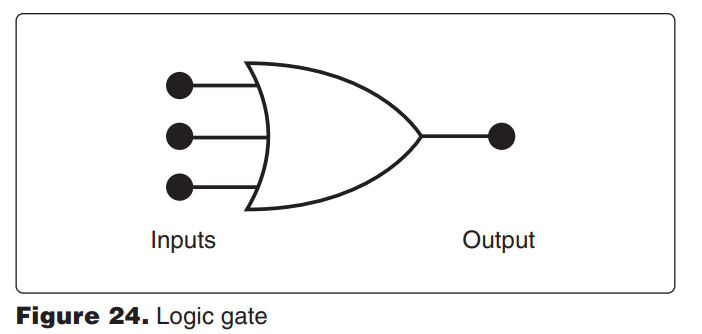
8082. (Refer to Figure 24.) Which statement concerning the depicted logic gate is true?
A—Any input being 1 will produce a 0 output.
B—Any input being 1 will produce a 1 output.
C—All inputs must be 1 to produce a 1 output.
[b] This is an OR gate. Any time there is a 1 on any of the inputs, there will be a 1 on the output. (AM.I.A.K22) — FAA-H-8083-30
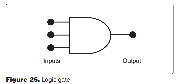
8083. (Refer to Figure 25.) In a functional and operating circuit, the depicted logic gate’s output will be 0
A—only when all inputs are 0.
B—when all inputs are 1.
C—when one or more inputs are 0.
[c] This is an AND gate. Any time one or more of the inputs do not have a 1 on them (have a 0 on them), the output will be 0. For the output to be 1, all of the inputs must be 1. (AM.I.A.K22) — FAA-H-8083-30
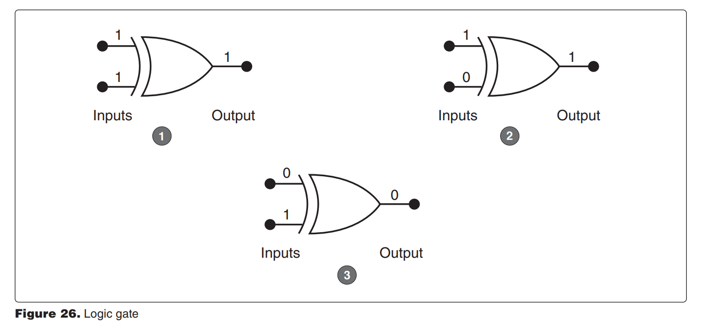
8084. (Refer to Figure 26.) Which of the logic gate output conditions is correct with respect to the given inputs?
A—1. B—2. C—3.
[b] These are EXCLUSIVE OR (XOR) gates. There will be a 1 on the output when one, and only one, input has a 1 on it. View 1 is incorrect. It has a 1 on both inputs so the output should be 0. View 2 is correct. Only one of the inputs has a 1 on it and the output is a 1. View 3 is incorrect. It has a 1 on one of its inputs, but the output is shown to be 0. (AM.I.A.K22) — FAA-H-8083-30
8084-1. Which of the following logic gates will provide an active high out only when all inputs are different?
A—XNOR.
B—NAND.
C—XOR.
[c] The output of the XOR gate will only be at an active high when one and only one of the two inputs is high. If both inputs are low, or both inputs are high, then the output of the gate will be low. (AM.I.A.K22) — FAA-H-8083-30