Fault tolerance control
1/17
There's no tags or description
Looks like no tags are added yet.
Name | Mastery | Learn | Test | Matching | Spaced | Call with Kai |
|---|
No analytics yet
Send a link to your students to track their progress
18 Terms
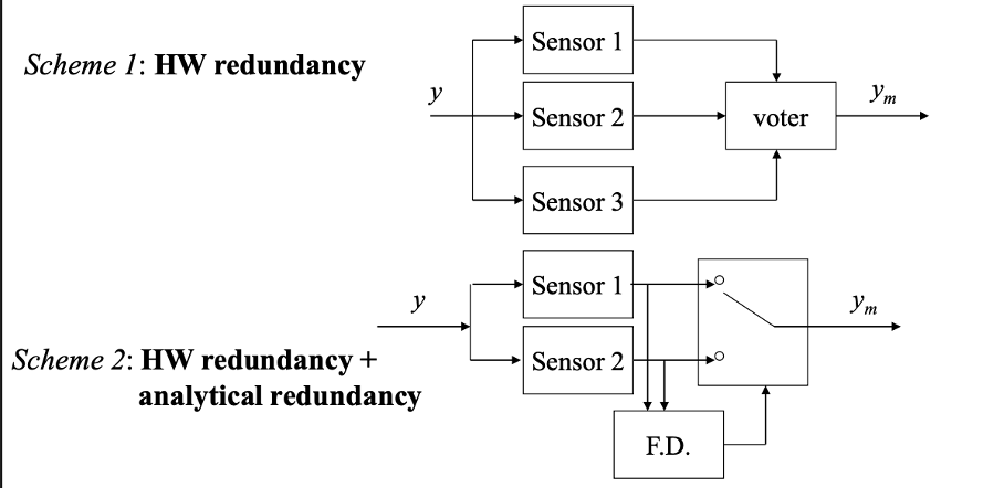
What three structures can be used for fault tolerance for sensor faults?
Using the 2-out of-3 principle
By having two sensors (economically beneficial) and a virtual one for fault detection
Self validating sensors: internal computational capability which provides an index of quality of the measurement
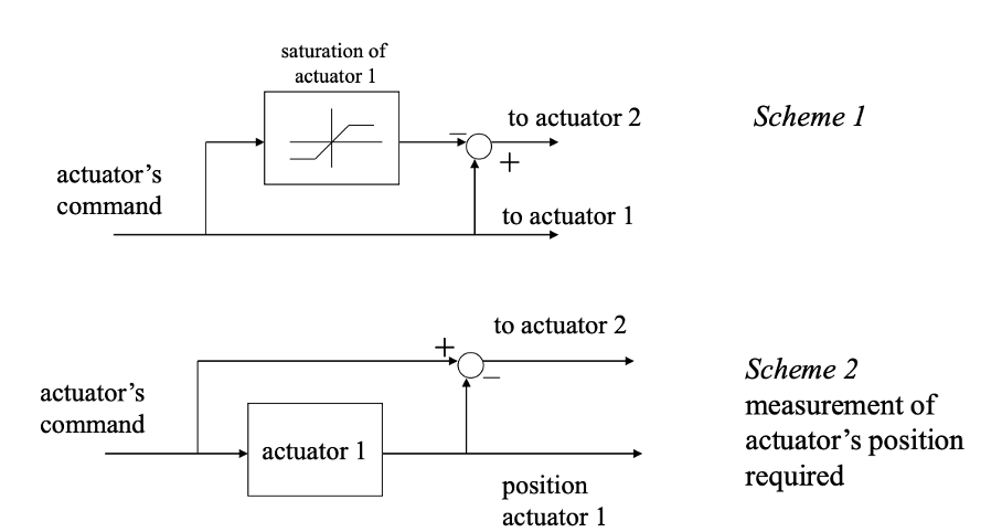
What structures can be used for fault tolerant control for actuators?
During normal conditions, one actuator is used while the other one is only used when the firs one is in fault or is saturated (daisy-chaining).
Scheme 1: if the saturation is reached for actuator one, the second actuator will be applied. So here the saturation is compare to what we want to get.
Scheme 2: you measure the output from actuator 1 and compare it with what you want and based on that difference, actuator 2 is activated.
Drawback: have to measure the output from actuator 1
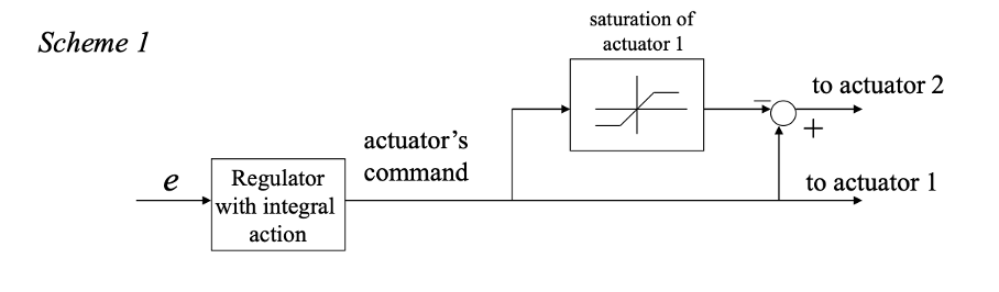
How can we identify faults for actuators with scheme 1 and scheme 2?
For scheme 1: we need a regulator with integral action. If the actuator 1 is in faul, the error grows with the integral action and actuator 2 starts working.
For scheme 2: Integral action is not needed but the measurement of the actuators output is required.
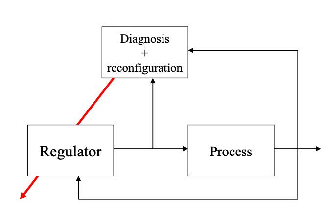
How should the general scheme for control, diagnosis and reconfiguration look like?
From the fault identification and fault isolation methods we will have information about the fault and that can be used to reconfigurate the system to have more fault tolerant control.

What is the difference between active and passive fault tolerance?
Once a fault has been isolated:
If the fault is negligible, it is not necessary to redesign the control system, since it should already have some robustness (passive fault tolerance)
If it is significant, but not too critical, it is possible to modify the control parameters without modifying the structure (active fault tolerance)
If it is critical, such as break of sensors or actuators, it is necessary to reconfigure the system (active fault tolerance)
Based on the diagnosis of the faults, some changes can have to be made for active fault tolerance control to the regulator. What can these changes be?
Changes of its parmeter (gain scheduling for instance), the resulting system is a time varying one
Change of its structure (and parameters), the resulting system is a hybrid system: asynchronous events (sudden leakage for ex) modify the structure
What is the drawback of doing changes on the regulator?
Time varying systems and hybrid systems are hard to analyse stability and performance properties on.
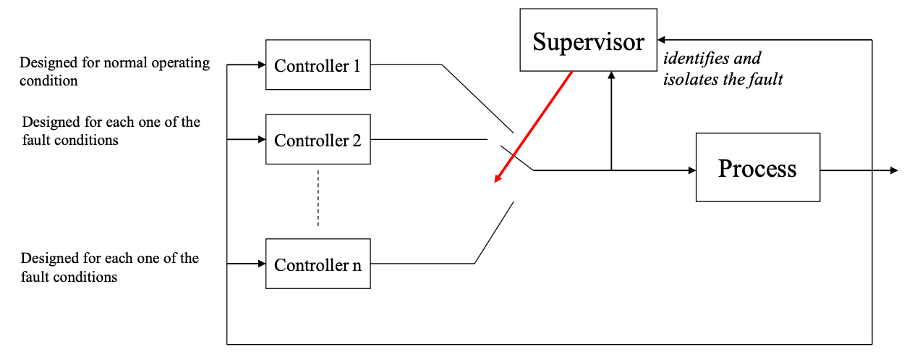
What approach can be used if you have one normal condition and n-1 known faults?
Switching systems:
A supervisors identifies and isolates the fault
You design n controllers for each fault condition
The supervisor switches controller based on the fault
The controllers can have the same structure, but different tunings. They must be implemented with suitable “tracking” procedures to avoid bumps when switches occur. Bumps when switches occurs can cause strong unexpected values which can break actuators or sensors.
If we have a fault on one actuator, how does the control scheme change?
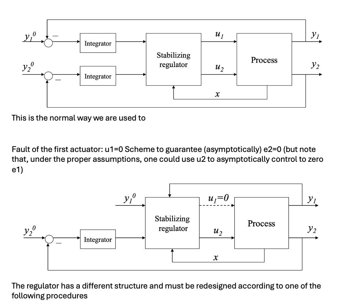
How can you redesign the regulator if you have a fault on one of the actuators?
You can use LQ control by solving the riccatti equation and then compute the optimal cost function with x0.
However you only use the set In (set of working actuators) to redesign your regulator.
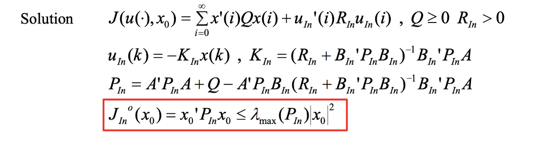
How do you devide the set I of inputs when actuator faults occur?
In (actuators properly working)
If (actuators in fault conditions)
Hos is it possible to compute the performance reduction from when you have all actuators working to only a subset?
Define the index:
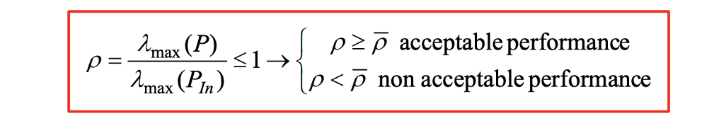
If rho is really small we don’t have acceptable performance.
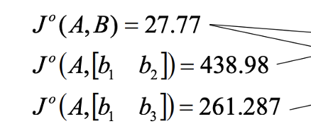
What does these cost functions mean for the actuators?
The cost of actuator 3 is higher than actuator 2 so the fault of actuator 3 is more critical.
If we instead have a fault on a sensor, what method can we use then?
Virtual sensors.
The idea is to reconstruct the missing output based on estimated states since the measured one is not available.
You compute the auxiliary output: The elements of the auxiliary output are equal to those of the true output when the corresponding measurements are available, while they are equal to the output computed by the observer when the corresponding sensor is in fault.
What is the effect of using in a feedback control scheme an estiamted output rather than a true one?
stability: the same of the nominal control law and of the observer (same eigenvalues)
reference signal response: if e(0)=0 and d=0, e(k)=0 and the response is equal to the nominal one.
Disturbance response: the observer dynamics influences the response also for e(0)=0, the response of the nominal system and of the system with the observer are not equal.
How can MPC be used in fault tolerant contorl?
MPC solves a new optimization problem for every time instant which allows one to include the occurence of sensors and/or actuators fault in the problem constraints.
In this way it is easy to reconfigure the control system.
This is done with the receding horizon approach. Usually an observer is used to estimate the state.
What can MPC help with for fault on sensors vs actuators?
Sensor faults:
It is possible to remove the corresponding error in the cost function to be minimized or
use a virtual sensor to estimate the value of the missing output along the predicted horizon
Actuator faults:
If the ith actuator is in fault, the corresponding control variable along the prediction horizon is set to zero u(k+j)=0
Obviously it must be verified that the performance required can be achieved (stability, tracking)
Can a dynamic regulator be used equivalently?
YEs.