CT 2
5.0(1)
5.0(1)
Card Sorting
1/32
Earn XP
Description and Tags
Study Analytics
Name | Mastery | Learn | Test | Matching | Spaced |
|---|
No study sessions yet.
33 Terms
1
New cards
Axial CT
Gantry stops + rotates to get data from single slice, X-rays switched off, pt moves to next slice, Rotates to acquire data from next slice
2
New cards
Helical CT
AKA spiral/volume CT
Gantry rotating continuously releasing x-ray beams
table simultaneously moves
results in a continuous spiral scanning pattern
Gantry rotating continuously releasing x-ray beams
table simultaneously moves
results in a continuous spiral scanning pattern
3
New cards
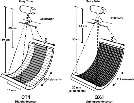
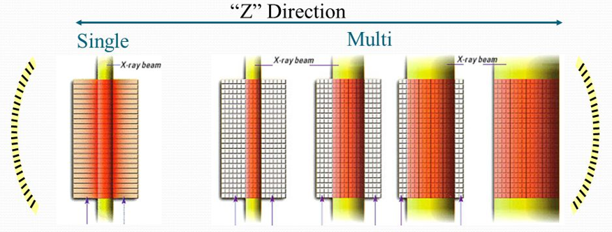
MDCT
Multi-Detector CT
2/more rows of parallel detector arrays
Allows acquisition of multiple slices in a single rotation
2/more rows of parallel detector arrays
Allows acquisition of multiple slices in a single rotation
4
New cards
Advantages of MDCT
Faster scanning time due to wider total active detector width
Fewer motion artefacts
Fewer motion artefacts
5
New cards
Reduced patient risk
Ideal for trauma imaging – cover entire pt in 1 scan
Fast scan times minimise time on table for critically ill patients
Paediatric scanning can be done with less sedation
Less contrast required reduces risk of adverse reaction
Fast scan times minimise time on table for critically ill patients
Paediatric scanning can be done with less sedation
Less contrast required reduces risk of adverse reaction
6
New cards
Thinner slices
Improved z-axis resolution
Isotropic imaging (equal voxel dimensions)
Improved multi-planar reformats (MPRs)
Improved 3D image rendering
Isotropic imaging (equal voxel dimensions)
Improved multi-planar reformats (MPRs)
Improved 3D image rendering
7
New cards
MDCT detector
slice thickness is determined by collimation
Electronic detector selection (detector switching)
Electronic detector selection (detector switching)
8
New cards
configuration
3 types:
Uniform/linear
Non-uniform/adaptive
Hybrid/mixed
Uniform/linear
Non-uniform/adaptive
Hybrid/mixed
9
New cards
Uniform
All rows have same size, width, thickness
10
New cards
Non-uniform
Not all equal
Smaller in middle, larger outside
Improves dose efficiency
Less division/ dead space
Expensive
Flexible
11
New cards
Hybrid
Set of narrow + set of non-uniform
Main type
12
New cards
Pitch
= ratio of distance moves per rotation to total w/ beam width
13
New cards
Higher pitch
less pt dose + quicker
Lower imaging quality because less images acquired
Lower imaging quality because less images acquired
14
New cards
lower pitch
more pt dose + quicker better imaging quality
15
New cards
Beam pitch
able distance travelled in 1 360 by gantry rotation divided by total thickness of all simultaneous acquired slice.
16
New cards
Pitch determination
Pitch determined by how quickly table moves ---> in MDCT, factor in total thickness because there are more than 1 detector
e.g. in multi: 7.5/4 * 2.5= 0.75 while in single 7.5/5.0=1.5
e.g. in multi: 7.5/4 * 2.5= 0.75 while in single 7.5/5.0=1.5
17
New cards
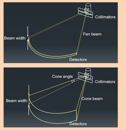
cone beam acquisition
Having more detectors and more slices means a having wider beam width
A cone beam is required to cover the whole detector width
A cone beam is required to cover the whole detector width
18
New cards
Cone Beam Reconstruction
With increased number of slices, the cone beam generates cone beam artefacts
As tube rotates, off-centre objects are visualised by different detector rows
As tube rotates, off-centre objects are visualised by different detector rows
19
New cards
Cone Beam Interpolation (2)
Tilted Reconstruction- produces non-axial images which are then filtered to produce standard axial images
‘Feldkamp Algorithm’ - a 3D back projection (standard FBP is planar + therefore 2D)
‘Feldkamp Algorithm’ - a 3D back projection (standard FBP is planar + therefore 2D)
20
New cards
Tilted (Oblique) Reconstruction
Reconstruct using BP, at an angle to the axial plane
Overlap reconstructions and filter along the z-axis
Basis of GE and Siemens techniques
Overlap reconstructions and filter along the z-axis
Basis of GE and Siemens techniques
21
New cards
Feldkamp Algorithm
Measurements are being taken from different angles for each patient ‘voxel’.
The section of pt being imaged is divided into 3D voxels rather than a 2D matrix of pixels as happens in back projection
The section of pt being imaged is divided into 3D voxels rather than a 2D matrix of pixels as happens in back projection
22
New cards
Image Quality in CT
image showing visibility of anatomical structures, various tissues, + signs of pathology
A measure of how suitable an image is for its intended diagnostic purpose
Suitability is determined if specific relevant criteria are met
A measure of how suitable an image is for its intended diagnostic purpose
Suitability is determined if specific relevant criteria are met
23
New cards
Desired attributes
Good image Q but low dose
Low noise
Fast scanning
Free of artefact
High spatial resolution
Less blurring
Low noise
Fast scanning
Free of artefact
High spatial resolution
Less blurring
24
New cards
Factors affecting CT
pt factor, reconstruction, scan parameters, viewing conditions, re solution
25
New cards
Noise
Variation in CT no. which isn't related to true attenuation co-efficient
Amount of ‘mottle’ in image
Amount of ‘mottle’ in image
26
New cards
Noise occurs because...
Random variation in photons detection – stochastic noise
stat fluctuation in x-ray production /interaction/detection
Electronic noise=measuring system
Reconstruction noise
stat fluctuation in x-ray production /interaction/detection
Electronic noise=measuring system
Reconstruction noise
27
New cards
disadvantage of noise
Lower noise= better LCD (low contrast detection)
Smooth image does not vary from the value
Noise= can mask detail
Smooth image does not vary from the value
Noise= can mask detail
28
New cards
Quantifying noise
Measure noise/deviation
Can be quantified: standard deviation in %
Can be quantified: standard deviation in %
29
New cards
Factors affecting noise
Scanner specifications and design
Scanning acquisition parameters
Reconstruction parameters
Patient factors
Scanning acquisition parameters
Reconstruction parameters
Patient factors
30
New cards
Scanner specifications and design
Efficiency of detectors
X-ray beam filtration
Scanner geometry
X-ray beam filtration
Scanner geometry
31
New cards
Scanning acquisition parameters
Tube voltage
Tube current
Scan time
Slice thickness
Pitch
Tube current
Scan time
Slice thickness
Pitch
32
New cards
Reconstruction parameters
Back projection algorithms
Noise filters
Noise filters
33
New cards
Patient factors
pt size