Energy Storage Elements, AC Circuits
1/62
There's no tags or description
Looks like no tags are added yet.
Name | Mastery | Learn | Test | Matching | Spaced | Call with Kai |
|---|
No analytics yet
Send a link to your students to track their progress
63 Terms
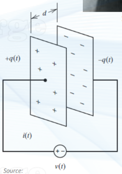
what is a capacitor?
a component in an electrical circuit that stores energy in an electric field
consists of two conductive plates separated by an insulator (called a dielectric)
voltage sources charges a capacitor
how does a capacitor work?
when a VOLTAGE is applied b/w the two conductive plates, one plate holds positive charge while the other holds negative charge
separation of charges creates an electric field in the dielectric, allowing the capacitor to temporarily store energy
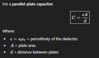
the capacitance of a capacitor is a constant value, and it’s given by:
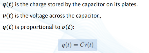
what is the formula for the charge stored in a capacitor at a given time?
what is the formula for the current running through a capacitor at a given time?
(ignore the second formula)
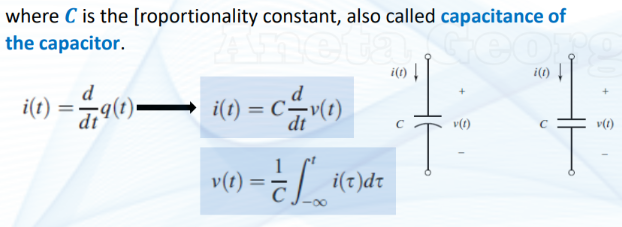
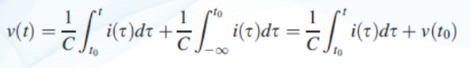
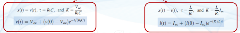
what is the formula for the voltage across the capacitor at a given time?
focus on the expression at the end
REMEMBER to include the initial voltage
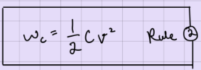
what is the formula for the energy (work) stored in a capacitor?
v = v(t)
remember that work = integral of power = integral of (current x voltage)
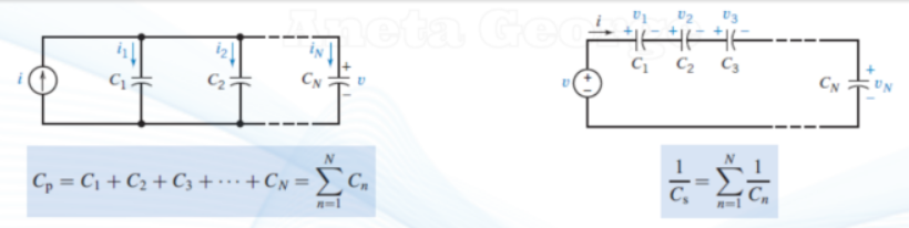
rules to combining multiple capacitors in a circuit
capacitors in series → use recip formula
capacitors in parallel → add together
what is an inductor?
a component that stores energy in a magnetic field when electric current flows through it
it’s usually made of a coil of wire wound around a core (the core is made up of air, iron, or another material)
how does an inductor work?
when current passes through the coil of, a MAGNETIC field is created around it, and the field stores energy
if the current changes, the magnetic field also changes, and this change creates a voltage that opposes (or tries to balance out) the change in current → this property is called inductance
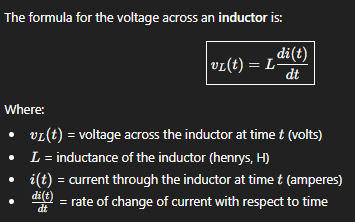
formula for the voltage across an inductor (induced by changes in current)
voltage is proportional to how fast the current changes (hence the derivative of current being in the formula)
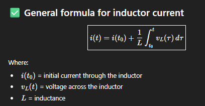
formula for the current through an inductor
do not forget to include the initial condition of the current
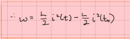
formula for the energy (work) stored in an inductor
w(t) >= 0 for all i(t) bc the inductor is a passive elem and can’t generate or dissipate energy, it can only store energy
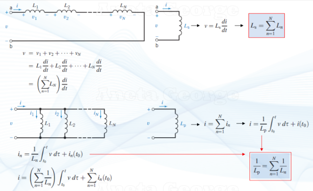
rules to combining multiple inductors in a circuit
inductors in series → add them together
inductors in parallel → use recip formula
what does steady state mean for a DC circuit
what qualifies as a DC circuit?
all sources output constant values
values become constant at steady state
RL and RC circuits can still be considered DC circuits after steady state
what is the steady-state in a DC circuit?
all currents and voltages have reached constant, unchanging values
a capacitor acts like an open circuit (no current flows)
an inductor acts like a short circuit (no volage drop)
all transients (charging/discharging/current ramps) have died out
you have to analyze circuits at three key time intervals. what are they?
t = 0
t < 0
t > 0
NOTE how the circuit “switch” behaves. it can either close at time 0 or open at time 0.
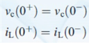
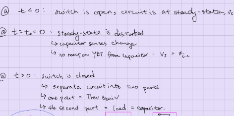
if a switch opens at t = 0, what would current and voltage for any capacitor/inductor in the circuit be immediately after it’s opened?
the values related to capacitor/inductor can not instantaneously change, so the values at t=0+ (right after switch is opened) would be the same as the values at t=0- (right before switch is opened)
see image
if a switch has been closed for a long time (therefore, it has reached steady state) at t < 0, what is the behaviour of the capacitors/inductors in the circuit?
at steady state and at t = 0-,
you can replace capacitors with open circuits (no current, constant voltage)
you can replace inductors with short circuits (constant current, no voltage)
if a switch as been open for a while at t > 0, how would capacitors/inductors behave in the circuit?
they act like normal → w/ transient properties:
capacitors continuously charge and discharge
inductors current rises or falls
you’d need to find v(t) and i(t) because the voltages/currents relating to those reactive components are no longer constant
BUT note that the circuit is a little different than if the swic
if a switch as been open for a while at t > infinity, how would capacitors/inductors behave in the circuit?
circuit is at steady state again
capacitor → open circuit
inductor → short circuit
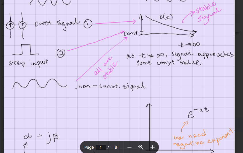
if you have a sinusoidal input, what would be the graphical shape of the output?
sinusoidal
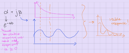
stable input signals and stable output signal
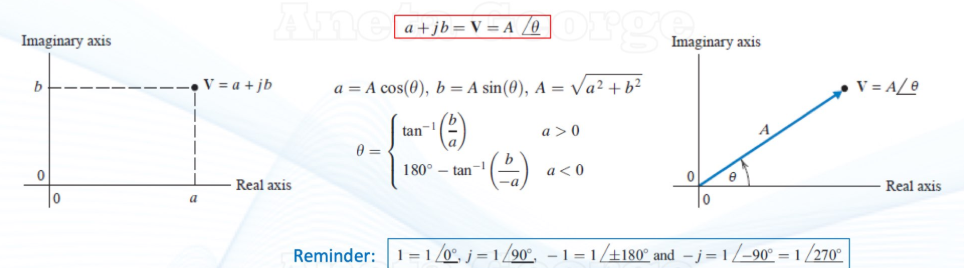
imaginary and real parts of a complex number on a cartesion plane
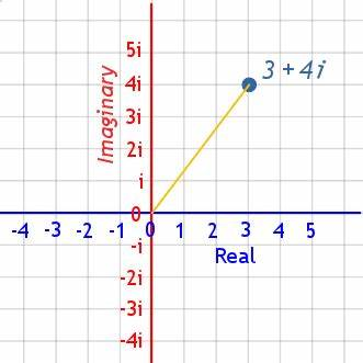
imaginary and real parts of a complex number, written
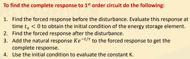
steps to finding the complete first order circuit response to a constant input
what is a first order circuit?
a circuit that has only ONE energy-storage element (either ONE capacitor or ONE inductor)
COMPLETE first order response
formula for τ (tau) when it’s an RC circuit (first order circuit with capacitor)
τ = Req * C
what does τ (tau) represent in first order circuit eqns?
the time it takes for the system to cover 63% of the final value
ex: if τ = 4, then it would take four seconds for the system to cover 63% of the final value
and 5*τ = the time it takes for the system to cover 100% of the final value
ex: if τ = 4, 5×4 = 20 = the time it takes for the system to cover 100% of the final value
τ ONLY applies to first order circuits
formula for τ (tau) when it’s an RL circuit (first order circuit with inductor)
τ = L/Req
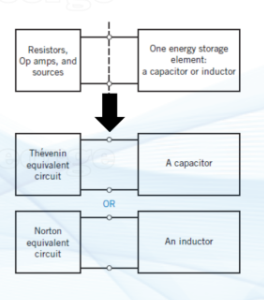
approach to analyzing a RC or RL first order circuit
simplify the rest of the circuit into Thevenin or Norton (depending on if it’s RC or RL)
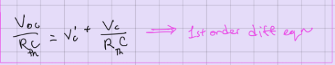
first order circuit differential equation (RC circuit)
(found using the Thevenin)
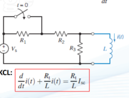
first order circuit differential equation (RL circuit)
equations for solving voltage/current equations in the capacitor/inductor in first order circuits
how the capacitor behaves in a RC circuit at t < 0, t = 0, and t > 0, where switch is closed at t = 0
at t < 0 (before switching
capacitor is fully charged
capacitor behaves like an open circuit bc there’s no current through the capacitor
capacitor voltage is constant
at t = 0 (instant of switching)
now there’s current, BUT voltage of capacitor is still constant because capacitor can’t change instantaneously
at t > 0
capacitor starts charging or discharging
ic’(t) = C*vc’(t)
voltage changes exponentially
at t → infinity (after a long time)
voltage reaches final value vc(infinity)
what is the condition for a circuit to be considered stable?
(τ = L/Req = Req * C) > 0 (tau must be positive)
what is a phasor?
a complex number (has an imaginary part and a real part, and an angle to rep phase angle) used to represent a sinusoidal AC signal (voltage or current) in the FREQUENCY domain rather than the time domain
phasors simplify the analysis of AC circuits by converting differential equations into algebraic linear eqns
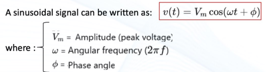
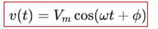
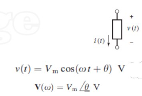
how is a sinusoidal signal written for an electrical signal?
you MUST always use a COS function
what is the corresponding phasor to this sinusoidal signal?
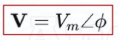

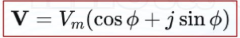
what is this phasor written in complex form?
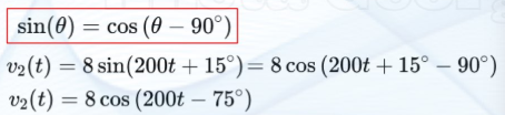
how to convert a sin function to a cos function
OR sin(theta) = - cos(theta + 90)
(minus sign is IMPORTANT)
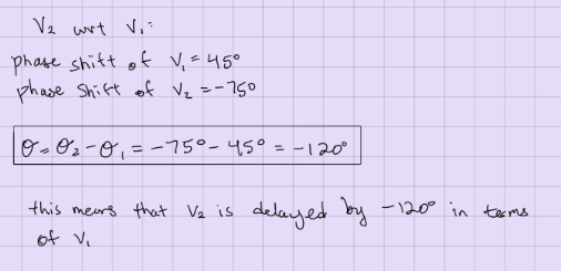
how to find the phase shift of one sinusoidal signal WRT the phase shift of another sinusoidal signal
this is how you determine if v2(t) is advanced or delayed wrt. v1(t)
v2(t) and v1(t) must be set to the same angular freq
how to det the time delay between electric signals
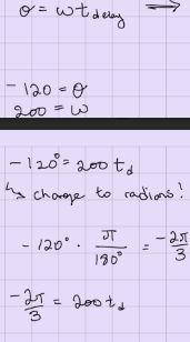
angular frequency = ω =
2*pi*freq
measured in rad/s
eqns for rectangular and polar forms of phasors
addition and subtraction w phasors
you must use the RECTANGULAR form of phasors
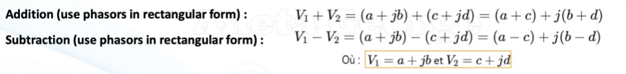
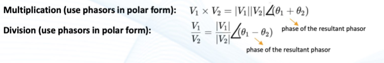
multiplication and division w phasors
you must use the POLAR form of phasors
what is the default phase angle for capacitor voltages
phase angle lags current by 90 degrees (-90)
what is the default phase angle for inductor voltages
phase angle leads current by 90 degrees (+90)
ohm’s law involving impedance
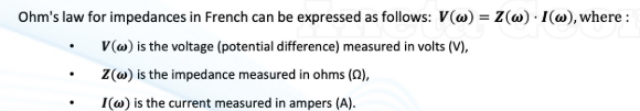
-j =
1/j
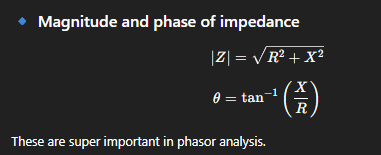
the magnitude and phase of impedance
imaginary/real
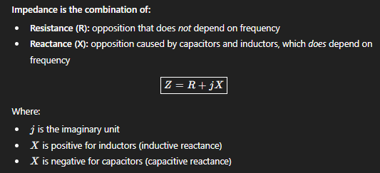
what is impedance?
impedance (symbol Z) = total opposition that a component presents to an alternating current (AC) and therefore includes both resistance (R) and reactance (X)
impedance of a resistor

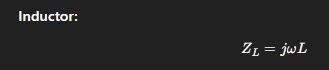
impedance of an inductor
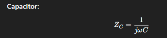
impedance of a capacitor
sinusoidal → phasor (voltage)
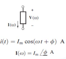
sinusoidal → phasor (current)
in terms of τ, when is the circuit essentially at steady state?
after about 5τ, the circuit is most likely at steady state
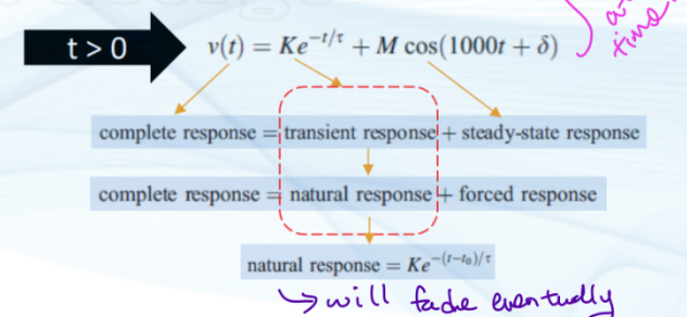
conceptual understanding of the complete first order response
complete response = natural response + forced response
→ complete response = exponential transition to final value + final value or final AC equation
the natural response eventually decays / dies out
the forced response remains
if DC: forced response → constant steady-state value
if AC: forced response → sinusoidal steady-state value
what is the inductor’s behaviour (constant input source) at t < 0, t = 0, and t > 0, where the switch CLOSES at t = 0
t < 0 (before switching, in DC steady state)
inductor current is constant whereas voltage equals 0, so it behaves like a short circuit
t = 0 (instant of switching)
inductor current can’t change instantaneously
the current at 0+ is the same as the current at 0- (t < 0)
voltage across inductor may jump (and you’d use the normal formula for vL(t)
t > 0
inductor current changes exponentially
after a long time (t → infinity), the inductor goes back to behaving like a short circuit because the current would have reached a final value iL(∞)