Lange - 5. Image Production: Equipment Operation and Quality Assurance
1/144
There's no tags or description
Looks like no tags are added yet.
Name | Mastery | Learn | Test | Matching | Spaced | Call with Kai |
|---|
No analytics yet
Send a link to your students to track their progress
145 Terms
1. Compared with the image on the input phosphor, the image on the output phosphor of the image intensifier is (select three)
A. magnified
B. distorted
C. brighter
D. dimmer
E. inverted
F. minified
1. (C, E, and F)
Light photons from the input phosphor strike the photocathode which emits electrons. These electrons are focused toward the output phosphor/screen by negatively charged electrostatic focusing lenses. They then pass through the neck of the image-intensifier tube where they are accelerated and strike the small 1.27-2.54 cm (1/2-1 inch) output screen, resulting in a minified image. Image minification and electron acceleration both account for increased brightness of the output image. For undistorted focusing of electrons onto the output screen, each electron must travel the same distance. This is accomplished by a slight curvature of the input screen, which is responsible for inverting the image on the output screen. The image on the input screen is reproduced as a minified image on the output screen. The output screen being much smaller than the input screen, the amount of fluorescent light emitted from it per unit area is significantly greater than the quantity of light emitted from the input screen.
2. Which of the following is/are components of the primary or low-voltage side of the x-ray circuit?
1. mA meter
2. Autotransformer
3. kV meter
A. 1 only
B. 1 and 2 only
C. 2 and 3 only
D. 1, 2, and 3
2. (C)
All circuit devices located before the primary coil of the high-voltage transformer are said to be on the primary or low-voltage side of the x-ray circuit. The timer, autotransformer, and (prereading) kilovoltage meter are all located in the low-voltage circuit.
The secondary/high-voltage side of the circuit begins with the secondary coil of the high-voltage transformer. The milliamperage meter is connected at the midpoint of the secondary coil of the high-voltage transformer. Following the secondary coil is the rectification system and the x-ray tube.
Transformers are used to change the value of alternating current (AC). They operate on the principle of mutual induction. The secondary coil of the step-up transformer is located on the high-voltage (secondary) side of the x-ray circuit. The step-down transformer, or filament transformer, is located in the filament circuit and serves to regulate the voltage and current provided to heat the x-ray tube filament. The rectification system is also located on the high-voltage, or secondary side of the x-ray circuit.
3. Which of the following is/are true statements regarding viewing conditions for digital images?
1. Excessive light causes dilation of the pupils of the eyes
2. Low-light level is desirable
3. Too much light causes images to appear dark
A. 1 only
B. 1 and 2 only
C. 2 and 3 only
D. 1, 2, and 3
3. (C)
Digital images are best viewed in areas with low-lighting levels that will avoid undesirable monitor screen glare. Digital images usually have a black "mask" covering the white unexposed areas, further reducing objectionable ambient light and glare. If the radiographer views images in a brightly lit area, the image can appear excessively dark. The same image, when reviewed by the radiologist, might look most adequate. As light level increases, the pupils of the eye contract and admit less light causing images to appear dark. It is an effect similar to walking from a sunny day into a darkened theater.
4. As FOV decreases in image intensification (select three)
A. output screen image is magnified
B. output screen image has more noise
C. mA increases
D. output screen image has improved resolution
E. the focal point is closer to the output phosphor
F. voltage to the focusing lenses is decreased
4. (A, C, and D)
Image-intensifier output phosphor/screen diameters of 5-12 inches are available. Although smaller diameter input screens improve resolution, they do not permit a large fluoroscopic FOV.
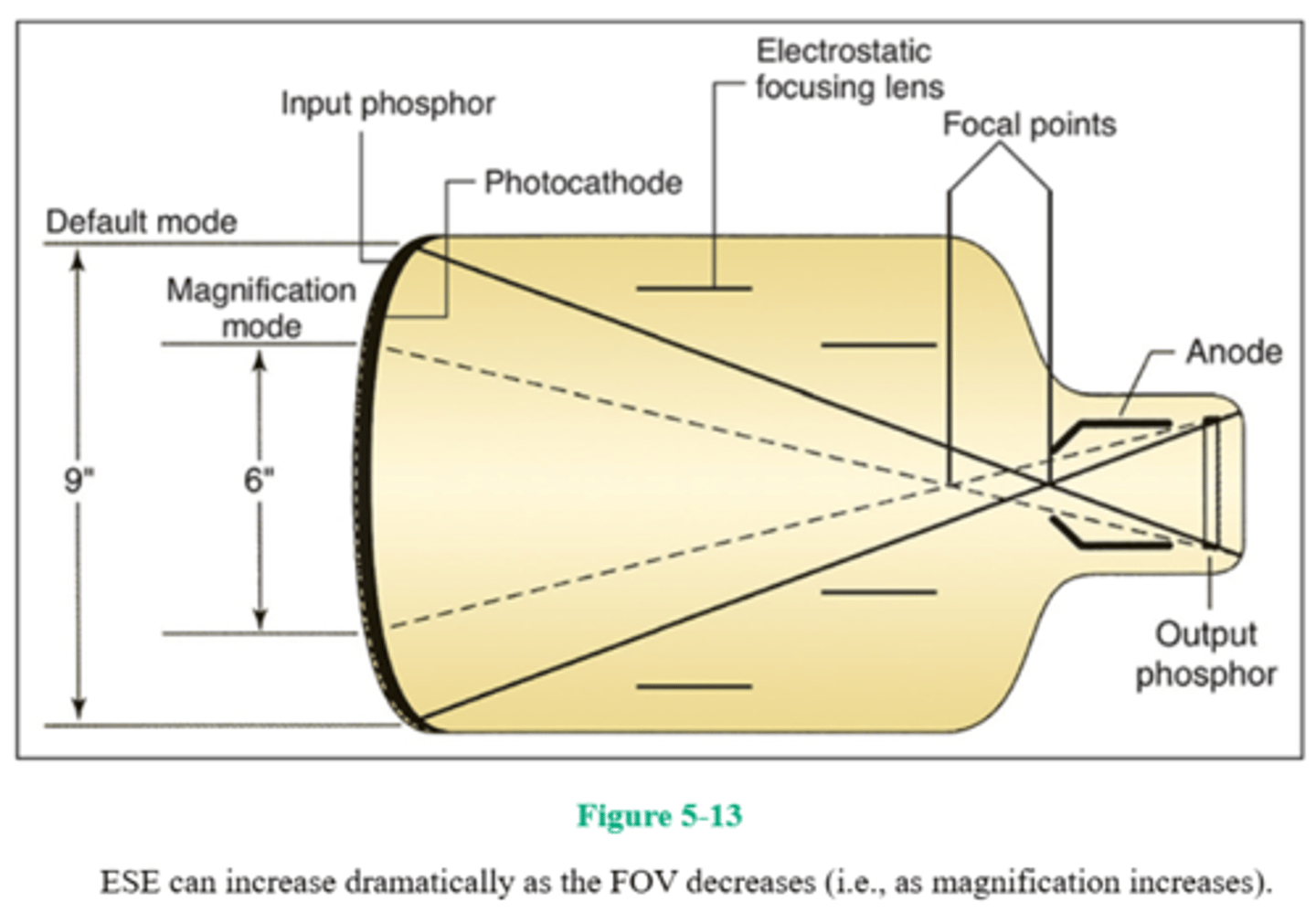
Dual- and triple-field image intensifiers are available that permit magnified viewing of fluoroscopic images. To achieve magnification, the voltage to the focusing lenses is increased and a smaller portion of the input phosphor is used, thereby resulting in a smaller FOV (and subsequent loss of brightness). The milliamperage is automatically increased to compensate for the loss in brightness when the image intensifier is switched to the magnification mode. When voltage applied to the focusing lenses increases, the focal point is further away from the output phosphor, and the output image is magnified.
ESE can increase dramatically as the FOV decreases (i.e., as magnification increases).
As FOV decreases, magnification of the output screen image increases, there is less noise because increased milliamperage provides a greater number of x-ray photons, and contrast and resolution improve. The focal point in the magnification mode is further away from the output phosphor (as a result of increased voltage applying to the focusing lenses) and therefore the output images magnified.
5. Design characteristics of x-ray tube targets that determine heat capacity include the
1. rotation of the anode
2. diameter of the anode
3. size of the focal spot
A. 1 only
B. 1 and 2 only
C. 1 and 3 only
D. 1, 2, and 3
5. (D)
Each time an x-ray exposure is made, less than 1% of the total energy is converted to x-rays, and the remainder (>99%) of the energy is converted to heat. Thus, it is important to use target material with a high atomic number and high-melting point. The larger the actual focal spot size is, the larger is the area over which the generated heat is spread, and the more heat tolerant the x-ray tube is. Heat is particularly damaging to the target if it is concentrated or limited to a small area. A target that rotates during the exposure is spreading the heat over a large area, the entire surface of the focal track. If the diameter of the anode is greater, the focal track will be longer and heat will be spread over an even larger area.
6. If exposure factors of 85 kV, 400 mA, and 12 ms yield an output exposure of 1.3 mGy, what is the value of milligray per milliampere seconds (mGy/mAs)?
A. 36.9
B. 17.2
C. 3.69
D. 0.27
6. (D)
Determining milligray per milliampere seconds output is often done to determine linearity among x-ray machines. However, all the equipment being compared must be of the same type (e.g., all single-phase or all three-phase, six-pulse). If there is linearity among these machines, then identical technique charts can be used. In the example given, 400 mA and 12 ms were used, equaling 4.8 mAs. If the output for 4.8 mAs was 1.3 mGy, then 1 mAs is equal to 0.27 mGy/4.8 mAs = 0.27 mGy/mAs).
7. The digital imaging processing function known as equalization (select three)
A. is a preprocessing function
B. is a computer software operation
C. removes high-frequency noise
D. removes densities that veil image details
E. compresses the contrast scale
7. (B, D, and E)
Equalization, or dynamic range control (DRC), is a postprocessing function of the computer software that actually compresses the contrast scale. It serves to remove densities that veil/obscure image details. If many very dark densities are removed, it permits visualization of previously hidden anatomic details. Removal of high-frequency noise is a function of the postprocessing function called smoothing or low-pass filtering.
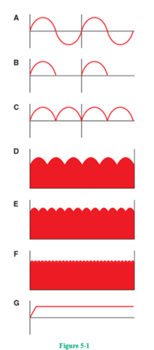
8. Which of the following waveforms shown in Figure 5-1 is illustrative of three-phase 12-pulse current?
A. Diagram D
B. Diagram E
C. Diagram F
D. Diagram G
8. (B)
Seven waveforms are illustrated in Figure 5-1. Figure 5-1A represents alternating current. Figure 5-1B illustrates half-wave rectification; each useful pulse (of x-ray) is followed by a pause of equal length. Figure 5-1C illustrates full-wave rectification. Note the 100% voltage ripple as each pulse starts at 0 potential, makes its way to 100%, and returns to 0 potential. Figure 5-1D represents three-phase, six-pulse current exhibiting a 13% voltage drop between peak potentials. Figure 5-1E represents three-phase, 12-pulse current having only about a 4% voltage drop between peak potentials. A big advantage of three-phase current is the very small drop in voltage between pulses. Figure 5-1F illustrates high-frequency current, which is most efficient and produces less than 1% voltage ripple. Here, 60-Hz full-wave-rectified current is converted to higher frequency (500-25,000 Hz). Mobile x-ray units first used this technology, because one of its greatest advantages is its small size. High-frequency generators are also used in mammography units and helical CT. More and more traditional x-ray equipment is using high-frequency technology because of its compact size, lower cost, and greater efficiency. Figure 5-1G illustrates direct current (DC).
9. Advantages of flat-panel fluoroscopy over image-intensified fluoroscopy include (select four) which of the following?
A. Greater maneuverability
B. Improved contrast resolution
C. Reduced DQE
D. Eliminates need for ADC
E. Considerably smaller size and weight
F. Images require smaller data files
9. (A, B, D, and E)
Flat-panel detectors (FPDs) used in fluoroscopy replace the large and bulky image intensifier. Smaller size and weight of FPDs permit greater maneuverability. The amorphous selenium direct-capture detector produces a digital signal so there is no need for a camera tube or ADC. The system is capable of recording both static images and dynamic images; however, these systems produce very large data files. The system produces higher spatial resolution, wider dynamic range, improved contrast resolution, and improved DQE—as compared with image-intensified fluoroscopy. In addition, patient dose decreases approximately 50% compared with image-intensified systems.
10. Which of the following terms is used to describe unsharp edges of tiny radiographic details?
A. Diffusion
B. Mottle
C. Blur
D. Umbra
10. (C)
Spatial resolution is evaluated by how sharply tiny anatomic details are imaged on the radiograph. The area of blurriness that may be associated with small image details is termed geometric blur. The blurriness can be produced by using a large focal spot or by diffused fluorescent light from intensifying screens. The image proper (i.e., without blur) is termed the umbra. Mottle is a grainy appearance caused by fast imaging systems.
11. How often are radiographic equipment collimators required to be evaluated?
A. Annually
B. Biannually
C. Semiannually
D. Quarterly
11. (C)
Quality control refers to our equipment and its safe and accurate operation. Various components must be tested at specified intervals, and test results must be within specified parameters. Any deviation from those parameters must be corrected. Examples of equipment components that are tested annually are the focal spot size, linearity, reproducibility, filtration, kilovoltage, and exposure time. Congruence is a term used to describe the relationship between the collimator light field and the actual x-ray field—they must be congruent (i.e., match) to within 2% of the SID. Radiographic equipment collimators should be inspected and verified as accurate semiannually, that is, twice a year. Kilovoltage settings can most effectively be tested using an electronic kilovoltage meter; to meet required standards, the kilovoltage should be accurate to within ±4 kV. Reproducibility testing should specify that radiation output be consistent to within ±5%.
12. Which of the following will improve the spatial resolution of image-intensified images?
1. A very thin input phosphor layer
2. A larger diameter input screen
3. Increased total brightness gain
A. 1 only
B. 1 and 2 only
C. 1 and 3 only
D. 1, 2, and 3
12. (A)
An image's spatial resolution refers to its recorded detail/sharpness. As the input phosphor layer (usually cesium iodide) is made thinner, detail sharpness (resolution) increases. Also, the smaller the input phosphor diameter, the greater is the spatial resolution. A brighter image is easier to see but, like mottle, does not affect image sharpness/resolution. Using magnification mode in image intensification does impact (and improve) spatial resolution (but does increase dose).
13. X-ray tube characteristics/qualities include which of the following?
1. The target material should have a high atomic number and a high-melting point
2. The useful beam emerges from the port window
3. The cathode assembly receives both low and high voltages
A. 1 only
B. 2 only
C. 1 and 2 only
D. 1, 2, and 3
13. (D)
Anode target material with a high atomic number produces higher energy x-rays more efficiently. Because a great deal of heat is produced at the target, the material should have a high-melting point so as to avoid damage to the target surface. X-rays produced at the target are emitted isotropically; those passing through the port window are the most useful diagnostically. The cathode filament receives low-voltage current to heat it to the point of thermionic emission. Then, high voltage is applied to drive the electrons across to the focal track.
14. A parallel-plate ionization chamber receives a particular charge as x-ray photons travel through it. This is the operating principle of which of the following devices?
A. AEC
B. Image intensifier
C. Video recorder
D. Photospot camera
14. (A)
A parallel-plate ionization chamber is a type of AEC. A radiolucent chamber is beneath the patient (between the patient and the IR). As photons emerge from the patient, they enter the chamber and ionize the air within it. Once a predetermined charge has been reached, the exposure is terminated automatically.
15. The total number of x-ray photons produced at the target is contingent on the
1. tube current
2. target material
3. square of the kilovoltage
A. 1 only
B. 1 and 2 only
C. 2 and 3 only
D. 1, 2, and 3
15. (D)
The greater the number of electrons making up the electron stream and bombarding the target, the greater is the number of x-ray photons produced. Although kilovoltage usually is associated with the energy of the x-ray photons, because a greater number of more energetic electrons will produce more x-ray photons, an increase in kilovoltage also will increase the number of photons produced. Specifically, the quantity of radiation produced increases as the square of the kilovoltage. The material composition of the tube target also plays an important role in the number of x-ray photons produced. The higher the atomic number of this material, the denser and more closely packed are the atoms making up the material, and therefore, the greater is the chance of an interaction between a high-speed electron and the target material.
16. Which of the following combinations would pose the greatest heat hazard to a particular single-phase anode?
A. 1.2-mm focal spot, 92 kV, 1.5 mAs
B. 0.6-mm focal spot, 80 kV, 3 mAs
C. 1.2-mm focal spot, 70 kV, 6 mAs
D. 0.6-mm focal spot, 60 kV, 12 mAs
16. (D)
Radiographic rating charts enable the radiographer to determine the maximum safe milliamperage, exposure time, and kilovoltage for a particular exposure using a particular x-ray tube. Focal spot size also plays an important role in determining heat-load capacity. An exposure that can be made safely with the large focal spot may not be safe for use with the small focal spot of the same x-ray tube. The total number of heat units that an exposure generates also influences the amount of stress (in the form of heat) imparted to the anode. The product of milliampere seconds and kilovoltage determines heat units. Group (A) produces 138 HU, group (B) produces 240 HU, group (C) produces 420 HU, and group (D) produces 720 HU. The most hazardous group of technical factors is, therefore, group (D). The larger the focal spot and smaller the milliampere seconds value, the greater the heat-load capacity.

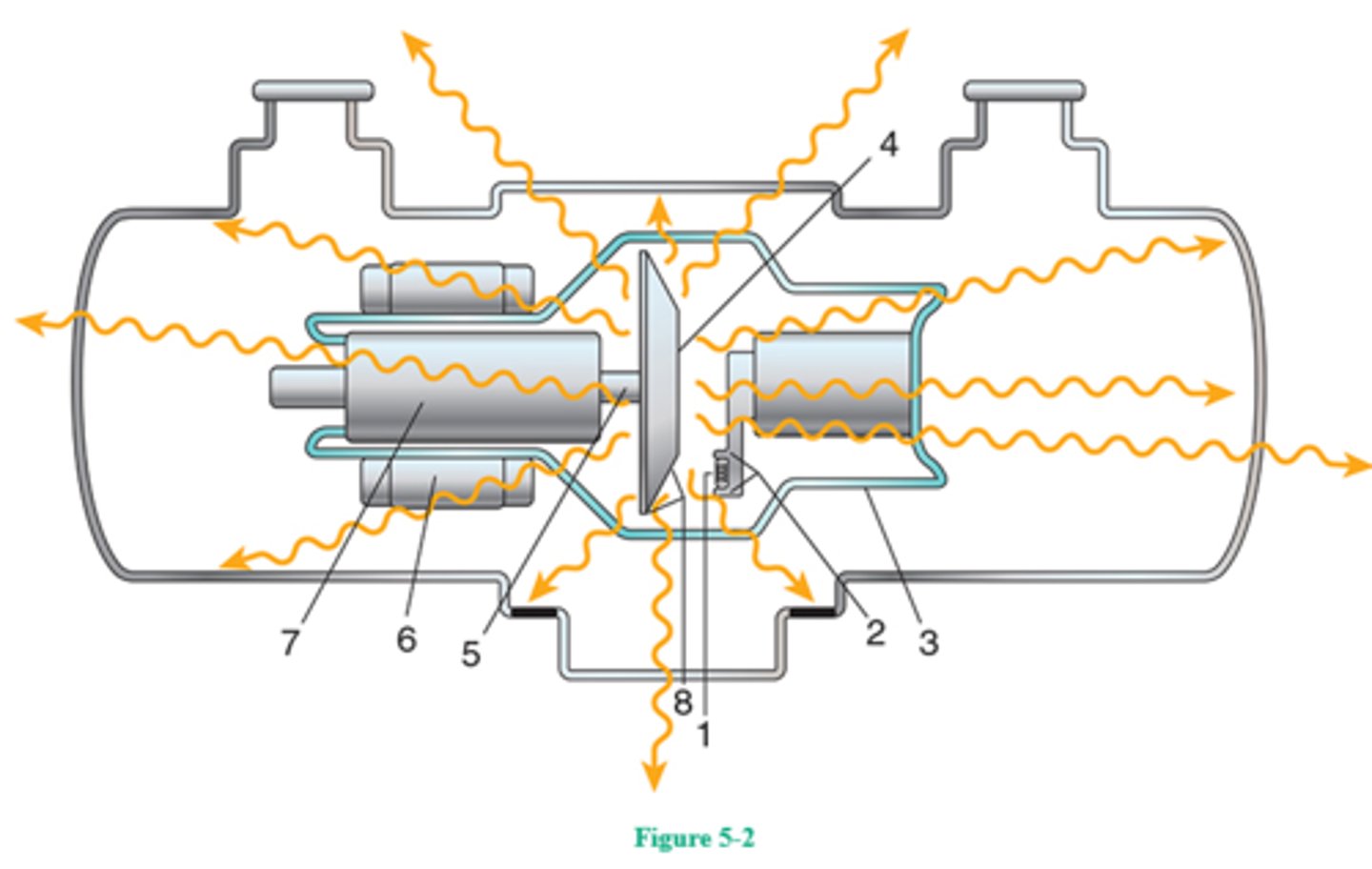
17. Of what material is number 1 in Figure 5-2 made?
A. Nickel
B. Molybdenum
C. Tungsten
D. Copper
17. (C)
Figure 5-2 illustrates the component parts of a rotating-anode x-ray tube enclosed within a glass envelope (number 3) that preserves the vacuum necessary for efficient x-ray production. Number 4 is the rotating anode, consisting of a light-weight molybdenum disk with beveled focal track at the periphery (number 8) and stem (number 5). The focal track is made of a tungsten-rhenium alloy. Numbers 6 and 7 are the stator and rotor, respectively—the two components of an induction motor—whose function is to rotate the anode. Number 1 is the filament of the cathode assembly, which is made of thoriated tungsten and functions to liberate electrons (thermionic emission) when heated to white hot (incandescence). Number 2 is the nickel focusing cup, which functions to direct the liberated filament electrons to the focal spot.

18. Which of the following systems functions to compensate for changes in patient/part thicknesses, FOV, and OID during flat-panel detector (FPD) fluoroscopic procedures?
A. Automatic exposure rate control
B. Electronic magnification
C. Automatic resolution control
D. Flux gain
18. (A)
Parts being examined during fluoroscopic procedures change in thickness and tissue density as the patient is required to change positions and as the fluoroscope is moved to examine different regions of the body. Changes in tissue attenuation characteristics, beam restriction, OID, and FOV can also necessitate an increase or decrease in exposure. The automatic exposure rate control (AERC) functions to vary the required changes in milliamperage, kilovoltage, pulse width, and even filtration as necessary. With AERC, beam intensity varies, and image quality is maintained. Electronic magnification is related to FOV selection. Flux gain is related to brightness gain.
19. Delivery of large exposures to a cold anode or the use of exposures exceeding tube limitation can result in
1. increased tube output
2. cracking of the anode
3. rotor-bearing damage
A. 1 only
B. 1 and 2 only
C. 2 and 3 only
D. 1, 2, and 3
19. (C)
A large quantity of heat applied to a cold anode can cause enough surface heat to crack the anode. Excessive heat to the target can cause pitting or localized melting of the focal track. Localized melts can result in vaporized tungsten deposits on the glass envelope, which can cause a filtering effect, decreasing tube output. Excessive heat also can be conducted to the rotor bearings, causing increased friction and tube failure.
20. Deposition of vaporized tungsten on the inner surface of the x-ray tube glass window
1. acts as additional filtration
2. results in increased tube output
3. results in anode pitting
A. 1 only
B. 1 and 2 only
C. 2 and 3 only
D. 1, 2, and 3
20. (A)
Through the action of thermionic emission, as the tungsten filament continually gives up electrons, it gradually becomes thinner with age. This evaporated tungsten frequently is deposited on the inner surface of the glass envelope at the tube window. When this happens, it acts as an additional filter to the x-ray beam, thereby reducing tube output. Also, the tungsten deposit actually may attract electrons from the filament, creating a tube current, and causing puncture of the glass envelope.
21. What is the relationship between kilovoltage and HVL?
A. As kilovoltage increases, the HVL increases
B. As kilovoltage decreases, the HVL increases
C. If the kilovoltage is doubled, the HVL doubles
D. If the kilovoltage is doubled, the HVL is squared
21. (A)
The HVL of a particular beam is defined as that thickness of a material that will reduce the exposure rate to one-half of its original value. The more energetic the beam (the higher the kilovoltage), the greater is the HVL thickness required to cut its intensity in half. Therefore, it may be stated that kilovoltage and HVL have a direct relationship: as kilovoltage increases, HVL increases.
22. As window width decreases
A. contrast scale increases
B. contrast scale decreases
C. brightness increases
D. brightness decreases
22. (B)
In electronic/digital imaging, changes in window width affect changes in contrast scale, whereas changes in window level affect changes in brightness. As window width increases, the scale of contrast increases (i.e., contrast decreases). Window level adjustments are associated with image brightness changes. This process can also be illustrated while postprocessing/windowing personal digital photographs or scanned documents.
23. Circuit devices that permit electrons to flow in only one direction are
A. solid-state diode rectifiers
B. resistors
C. transformers
D. autotransformers
23. (A)
Rectifiers change AC into unidirectional current by allowing current to flow through them in only one direction. Valve tubes are vacuum rectifier tubes found in older equipment. Solid-state diodes are the types of rectifiers used in x-ray equipment these days. Rectification systems are found between the secondary coil of the high-voltage transformer and the x-ray tube. Resistors, such as rheostats or choke coils, are circuit devices used to vary voltage or current. Transformers, operating on the principle of mutual induction, change the voltage (and current) to useful levels. Autotransformers, operating on the principle of self-induction, enable us to select the required kilovoltage.
24. Scintillation is associated with all the following, except
A. amorphous silicon
B. amorphous selenium
C. cesium iodide
D. gadolinium oxysulfide
24. (B)
Phosphors that fluoresce are said to scintillate. Fluorescent/scintillating phosphors used in indirect-conversion systems include amorphous silicon, cesium iodide, and gadolinium oxysulfide. Amorphous selenium is used in direct-conversion systems and functions to convert to x-ray photon energy into electrical charges.
25. The AEC backup timer functions to
1. protect the patient from overexposure
2. protect the x-ray tube from excessive heat
3. increase or decrease programmed receptor exposure
A. 1 only
B. 1 and 2 only
C. 2 and 3 only
D. 1, 2, and 3
25. (B)
When an AEC is installed in an x-ray circuit, it is calibrated to produce radiographic densities as required by the radiologist. Once the part being radiographed has been exposed to produce the correct receptor exposure, the AEC automatically terminates the exposure. The manual timer should be used as a backup timer; in case the AEC fails to terminate the exposure, the backup timer would protect the patient from overexposure and the x-ray tube from excessive heat load. The master receptor exposure override generally is set on normal to produce the required receptor exposure. In special cases, when this produces excessive or insufficient receptor exposure, the master receptor exposure override may be adjusted to plus or minus position.
26. Which of the following devices converts mechanical energy to electrical energy?
A. Motor
B. Generator
C. Stator
D. Rotor
26. (B)
A generator converts mechanical energy into electrical energy—as alternating or direct current. A motor is a device used to convert electrical energy to mechanical energy. The stator and rotor are the two principal parts of an induction motor.
27. The filtering effect of the x-ray tube's glass envelope and its oil coolant are collectively called
A. inherent filtration
B. added filtration
C. compensating filtration
D. port filtration
27. (A)
The x-ray photons emitted from the anode focus are heterogeneous in nature. The low-energy photons must be removed because they are not penetrating enough to contribute to the image and because they do contribute to the patient's skin dose. The glass envelope and oil coolant provide approximately 0.5- to 1.0-mm Al equivalent filtration, which is called inherent because it is a built-in, permanent part of the tube head.
28. A slit camera is used to measure
1. focal spot size
2. spatial resolution
3. dynamic range
A. 1 only
B. 1 and 2 only
C. 1 and 3 only
D. 1, 2, and 3
28. (B)
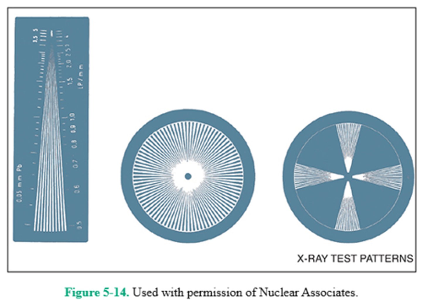
A quality assurance (QA) program requires the use of a number of devices to test the efficiency of various parts of the imaging system. Spatial resolution is significantly affected by focal spot size. A slit camera, as well as a star pattern (Fig. 5-14), or pinhole camera, is used to test focal spot size. The slit camera is considered the standard for (annual) measurement of the effective focal spot size. Dynamic range is the range of exposures that can be captured by a detector, and is unrelated to measurement of focal spot.
29. All of the following statements regarding mobile radiographic equipment are true, except
A. exposure switches must be the "dead-man" type
B. the radiographer must alert individuals in the area before making the exposure
C. the exposure cord must permit the operator to stand at least 4 feet from the patient, x-ray tube, and useful beam
D. a lead apron should be carried with the unit and worn by the radiographer during exposure
29. (C)
NCRP Report No. 102 states that the exposure switch on mobile radiographic units shall be so arranged that the operator can stand at least 2 m (6 feet) from the patient, the x-ray tube, and the useful beam. An appropriately long exposure cord accomplishes this requirement. The fluoroscopic and/or radiographic exposure switch or switches must be of the "dead-man" type, that is, the exposure will terminate should the switch be released. At least one lead apron should be carried with every mobile x-ray unit for the operator to wear during the exposure. Finally, the radiographer must be certain to alert individuals in the area, enabling unnecessary occupants to move away, before making the exposure. Many facilities require a second lead apron to be available for family/staff/patient who are unable to leave.
30. Which of the following causes pitting, or many small surfaces melt, of the anode's focal track?
A. Vaporized tungsten on the glass envelope
B. Loss of anode rotation
C. A large amount of heat to a cold anode
D. Repeated, frequent overloading
30. (D)
As the filament ages, vaporized tungsten may be deposited on the port window and act as an additional filter. Tungsten may also vaporize as a result of anode abuse. Exposures in excess of safe values deliver sufficient heat to cause surface melts, or pits, on the focal track. This results in roughening of the anode surface and decreased tube output. Delivery of a large amount of heat to a cold anode can cause cracking if the anode does not have sufficient time to disperse the heat. Loss of anode rotation would cause one large melt on the focal track because the electrons would bombard only one small area. If the anode is not heard to be rotating, the radiographer should not make an exposure.
31. The advantages of collimators over aperture diaphragms and flare cones include which of the following?
1. The variety of field sizes available
2. More efficient beam restriction
3. Better cleanup of scattered radiation
A. 1 only
B. 1 and 2 only
C. 1 and 3 only
D. 2 and 3 only
31. (B)
There are three types of beam restrictors—aperture diaphragms, cones and cylinders, and collimators. The most practical and efficient type is the collimator. Its design makes available an infinite number of field-size variations that are not available with the other types of beam restrictors. Because aperture diaphragms and flare cones have a fixed aperture size and shape, their beam restriction is not as efficient as that of the variable size collimator. Aperture diaphragms, cones, and cylinders may be placed on a collimator track so that the illuminated crosshairs are visualized. Although the collimator assembly contributes approximately 1.0-mm Al equivalent to the added filtration of the x-ray tube (because of the plastic exit portal and silver-coated reflective mirror), its functions are unrelated to the cleanup of scattered radiation. This is so because the patient is the principal scatterer, and grids function to clean up scattered radiation generated by the patient.
32. Which of the following evaluates focal spot accuracy as a function of geometric blur?
A. Pinhole camera
B. Slit camera
C. Star pattern
D. Focus pattern
32. (C)
Focal spot size accuracy is related to the degree of geometric blur, that is, edge gradient or penumbra. Manufacturer tolerance for new focal spots is 50%, that is, a 0.3-mm focal spot actually may be 0.45 mm. In addition, the focal spot can increase in size as the x-ray tube ages; hence, the importance of testing newly arrived focal spots and periodic testing to monitor focal spot changes. Focal spot size can be measured with a pinhole camera, slit camera, or star-pattern-type resolution device. The pinhole camera is rather difficult to use accurately and requires the use of excessive tube (heat) loading. With a slit camera, two exposures are made; one measures the length of the focal spot, and the other measures the width. The star pattern, or similar resolution device, such as the bar pattern, can measure focal spot size as a function of geometric blur and is readily adaptable in a QA program to monitor focal spot changes over a period of time. It is recommended that focal spot size be checked on installation of a new x-ray tube and annually thereafter.
33. Which of the following are the characteristics of the metallic element tungsten?
1. Ready dissipation of heat
2. High-melting point
3. High atomic number
A. 1 only
B. 1 and 2 only
C. 2 and 3 only
D. 1, 2, and 3
33. (D)
The x-ray anode may be a molybdenum disk coated with a tungsten-rhenium alloy. Because tungsten has a high atomic number (74), it produces high-energy x-rays more efficiently. Because a great deal of heat is produced at the target, tungsten's high-melting point (3410°C) helps to avoid damage to the target surface. Heat produced at the target should be dissipated readily, and tungsten's conductivity is similar to that of copper. Therefore, as heat is applied to the focus, it can be conducted throughout the disk to equalize the temperature and thus avoid pitting, or localized melting, of the focal track.
34. What grid ratio is represented in the illustration shown in Figure 5-3?
A. 5:1
B. 8:1
C. 12:1
D. 16:1
34. (D)
Grid ratio is defined as the height of the lead strips compared to (divided by) the width of the interspace material. The width of the lead strips has no bearing on the grid ratio. The height of these lead strips is 8 mm; the width of the interspace material (that is the same as the distance between the lead strips) is 0.5 mm.
Therefore, the grid ratio is 8/0.5, or a 16:1 grid.
35. The voltage ripple associated with a three-phase, six-pulse rectified generator is about
A. 4%
B. 13%
C. 32%
D. 100%
35. (B)
Voltage ripple refers to the percentage drop from maximum voltage each pulse of current experiences. In single-phase rectified equipment, the entire pulse (half-cycle) is used; therefore, there is first an increase to the maximum (peak) voltage value and then a decrease to zero potential (90° past peak potential). The entire waveform is used; at 100 kV, the actual average kilovoltage output would be approximately 70 kV. Three-phase rectification produces almost constant potential, with small ripples (drops) in maximum potential between pulses. Approximately a 13% voltage ripple (drop from maximum value) characterizes the operation of three-phase, six-pulse generators. Three-phase, 12-pulse generators have about a 4% voltage ripple. High-frequency current is most efficient and produces less than 1% voltage ripple. The high-frequency generator is small in size and produces an almost constant potential waveform.
36. Which of the following modes of a triple-field image intensifier will result in the highest patient dose?
A. Its 25-inch mode
B. Its 17-inch mode
C. Its 12-inch mode
D. Diameter does not affect patient dose
36. (C)
Most image-intensifier tubes are either dual-field or triple-field, indicating the diameter of the input phosphor. When a change to a smaller diameter mode is made, the voltage on the electrostatic focusing lenses is increased, and the result is a magnified but dimmer image. The milliamperage will be increased automatically to compensate for the loss in brightness with a magnified image, resulting in higher patient dose in the smaller diameter modes.
37. A high-speed electron is decelerated as it is attracted to a tungsten atom nucleus. This results in
A. Bremsstrahlung radiation
B. characteristic radiation
C. Compton scatter
D. a photoelectric effect
37. (A)
The incident electron has a certain amount of energy as it approaches the tungsten target. If the positive nucleus of a tungsten atom attracts the electron, changing its course, a certain amount of energy is released during the "braking" action. This energy is given up in the form of an x-ray photon called Bremsstrahlung (braking) radiation. Characteristic radiation is also produced at the target (less frequently) when an incident electron ejects a K-shell electron, and an L-shell electron drops into its place. Energy is liberated in the form of a characteristic ray, and its energy is representative of the difference in energy levels. Compton scatter and the photoelectric effect are interactions between x-ray photons and tissue atoms.
38. All of the following are components of the image intensifier, except
A. the photocathode
B. the focusing lenses
C. the TV monitor
D. the accelerating anode
38. (C)
The input phosphor of an image intensifier receives remnant radiation emerging from the patient and converts it to a fluorescent light image. Directly adjacent to the input phosphor is the photocathode, which is made of a photoemissive alloy (usually, a cesium and antimony compound). The fluorescent light image strikes the photocathode and is converted to an electron image. The electrons are focused carefully, to maintain image resolution, by the electrostatic focusing lenses, through the accelerating anode and to the output phosphor for conversion back to light. The TV monitor is not part of the image intensifier but serves to display the image that is transmitted to it from the output phosphor.
39. Which of the following are components of digital imaging?
1. Computer manipulation of the image
2. Formation of an electronic image on the radiation detector
3. Formation of an x-ray image directly on the IR
A. 1 only
B. 1 and 2 only
C. 2 and 3 only
D. 1, 2, and 3
39. (B)
In digital imaging, x-rays form an electronic image on a special radiation detector. This electronic image can be manipulated by a computer and stored in the computer memory or displayed as a matrix of intensities. This final digital image can be viewed on a computer monitor and the computer has the capability of postprocessing and image enhancement.
40. Which of the following is used in digital fluoroscopy (DF), replacing the image intensifier's television camera tube?
A. Solid-state diode
B. Charge coupled device
C. Photostimulable phosphor
D. Vidicon
40. (B)
In DF, the image-intensifier output screen image is coupled via a charge coupled device (CCD) for viewing on a display monitor. A CCD converts visible light to an electrical charge that is then sent to the analog-to-digital converter (ADC) for processing. When output screen light strikes the CCD cathode, a proportional number of electrons are released by the cathode and stored as digital values by the CCD. The CCD's rapid discharge time virtually eliminates image lag and is useful in high-speed imaging procedures, such as cardiac catheterizations. CCD cameras have replaced analog cameras (e.g., the Vidicon and Plumbicon) in fluoroscopic equipment. CCDs are more sensitive to the light emitted by the output phosphor (than the analog cameras) and are associated with less "noise." DF photospot images are simply still-frame images requiring less patient dose, and offering postprocessing capability. DF also offers "road-mapping" capability, a technique useful in procedures involving guidewire/catheter placement. During the fluoroscopic examination, the most recent fluoroscopic image is stored on the monitor, thereby reducing the need for continuous x-ray exposure. This technique can offer significant reductions in radiation exposure to the patient and personnel.
41. With what frequency must radiographic equipment be checked for linearity and reproducibility?
A. Annually
B. Biannually
C. Semiannually
D. Quarterly
41. (A)
Quality control refers to our equipment and its safe and accurate operation. Various components must be tested at specified intervals and test results must be within specified parameters. Any deviation from those parameters must be corrected. Examples of equipment components that are tested annually are the focal spot size, linearity, reproducibility, filtration, kilovoltage, and exposure time. Reproducibility specifies that radiation output must be consistent to within ±5%. Linearity tests x-ray output with increasing milliampere seconds value; mR/mAs should be accurate to within 10%. Kilovoltage settings can most effectively be tested using an electronic kilovoltage meter; to meet required standards, the kilovoltage should be accurate to within ±4 kV. Congruence is a term used to describe the relationship between the collimator light field and the actual x-ray field—they must be congruent to within 2% of the SID. Radiographic equipment collimators should be inspected and verified as accurate semiannually.
42. The regular measurement and evaluation of radiographic equipment components and their performance is most accurately termed as
A. postprocessing
B. quality assurance
C. quality control
D. quality congruence
42. (C)
Quality control refers to our equipment and its safe and accurate operation. Various components must be tested at specified intervals and test results must be within specified parameters. Any deviation from those parameters must be corrected. Examples of equipment components that are tested annually are the focal spot size, linearity, reproducibility, collimation, filtration, kilovoltage, and exposure time. Quality assurance is associated with patients and staff, and their interactions and relationships. Congruence is a term used to describe the relationship between the collimator light field and the actual x-ray field—they must be congruent (i.e., match) to within 2% of the SID. Postprocessing refers to the windowing or other manipulation of a digital image.
43. Which of the following are typical examples of digital imaging?
1. MRI
2. CT
3. CR
A. 1 only
B. 1 and 2 only
C. 1 and 3 only
D. 1, 2, and 3
43. (D)
CT (computed tomography), MRI (magnetic resonance imaging), and CR (computed radiography) are three common examples of digital imaging. Special equipment is also available for direct digital radiography (DR)—images produced by either a fan-shaped x-ray beam received by linearly arrayed radiation detectors or a traditional fan-shaped x-ray beam received by a light-stimulated phosphor plate. Digital images can also be obtained in digital subtraction angiography (DSA), nuclear medicine, and diagnostic sonography.
44. In fluoroscopy, the automatic brightness control is used to adjust the
A. kilovoltage (kV) and milliamperage (mA)
B. backup timer
C. milliamperage (mA) and time
D. kilovoltage (kV) and time
44. (A)
As body areas of different thicknesses and densities are scanned with the image intensifier, image brightness and contrast require adjustment. The ABC functions to maintain constant brightness and contrast of the output screen image, correcting for fluctuations in x-ray beam attenuation with adjustments in kilovoltage and/or milliamperage. There are also brightness and contrast controls on the monitor that the radiographer can regulate.
45. Which of the following terms describes the amount of electric charge flowing per second?
A. Voltage
B. Current
C. Resistance
D. Capacitance
45. (B)
Current is defined as the amount of electric charge flowing per second. Voltage is the potential difference existing between two points. Resistance is the property of a circuit that opposes current flow. Capacitance describes a quantity of stored electricity.
46. How often are radiographic equipment kilovoltage settings required to be evaluated?
A. Annually
B. Biannually
C. Semiannually
D. Quarterly
46. (A)
Quality control refers to our equipment and its safe and accurate operation. Various components must be tested at specified intervals and test results must be within specified parameters. Any deviation from those parameters must be corrected. Examples of equipment components that are tested annually are the focal spot size, linearity, reproducibility, filtration, kilovoltage, and exposure time. Kilovoltage settings can most effectively be tested using an electronic kilovoltage meter; to meet required standards, the kilovoltage should be accurate to within ±4 kV. Congruence is a term used to describe the relationship between the collimator light field and the actual x-ray field—they must be congruent (i.e., match) to within 2% of the SID. Collimators should be inspected and verified as accurate semiannually. Reproducibility testing should specify that radiation output be consistent to within ±5%.
47. What is the device that directs the light emitted from the image intensifier to various viewing and imaging apparatus?
A. Output phosphor
B. Beam splitter
C. Spot image device
D. Automatic brightness control
47. (B)
The light image emitted from the output phosphor of the image intensifier is directed to the TV monitor for viewing and sometimes to recording devices, such as a spot image or cine device. The light is directed to these places by a beam splitter or objective lens located between the output phosphor and the CCD. The majority of the light will go to the recording device, whereas a small portion goes to the monitor so that the procedure may continue to be observed during imaging.
48. The image-intensifier tube's input phosphor functions to convert
A. kinetic energy to light
B. x-rays to light
C. electrons to light
D. fluorescent light to electrons
48. (B)
The image intensifier's input phosphor receives the remnant radiation emerging from the patient and converts it into a fluorescent light image. Very close to the input phosphor, separated by a thin, transparent layer, is the photocathode. The photocathode is made of a photoemissive alloy, usually an antimony and cesium compound. The fluorescent light image strikes the photocathode and is converted to an electron image that is focused by the electrostatic lenses to the output phosphor.
49. Which of the following contribute(s) to inherent filtration?
1. X-ray tube glass envelope
2. X-ray tube port window
3. Aluminum between the tube housing and the collimator
A. 1 only
B. 1 and 2 only
C. 1 and 3 only
D. 1, 2, and 3
49. (B)
Inherent filtration is that which is "built into" the construction of the x-ray tube. Before exiting the x-ray tube, x-ray photons must pass through the tube's glass envelope and port window; the photons are filtered somewhat as they do so. This inherent filtration is usually the equivalent of 0.5 mm Al. Aluminum filtration placed between the x-ray tube housing and the collimator is added to contribute to the total necessary requirement of 2.5-mm Al equivalent. The collimator itself is considered part of the added filtration (1.0-mm Al equivalent) because of the silver surface of the mirror within. It is important to remember that as aluminum filtration is added to the x-ray tube, the HVL increases.
50. Digital imaging subject contrast is the result of
A. x-ray beam quantity and quality
B. varying intensities of the primary beam
C. signal differences within the remnant beam
D. grid ratio and alignment
50. (C)
Normal tissue variants and pathologic processes that alter tissue thickness and composition can have a significant effect on degree of alteration of the applied x-ray beam—and, ultimately, on the characteristics of the remnant beam. The degree to which the x-ray beam is weakened/diminished by varying tissues is termed differential absorption. These tissue variants affect differential absorption, the amount of SR generated, and the number of photons reaching the IR. Subject contrast refers to the various body tissue densities and thicknesses, which results in differential absorption of the x-ray beam and the resulting signal differences within the remnant beam.
51. Which x-ray tube component does the number 7 in Figure 5-4 indicate?
A. Anode stem
B. Rotor
C. Stator
D. Focal track
51. (B)
Figure 5-4 illustrates the component parts of a rotating-anode x-ray tube enclosed within a glass envelope (number 3) to preserve the vacuum necessary for x-ray production. Number 4 is the rotating anode with its beveled focal track at the periphery (number 8) and its stem (at number 5). Numbers 6 and 7 are the stator and rotor, respectively—the two components of an induction motor—whose function is to rotate the anode. Number 1 is the filament of the cathode assembly, which is made of thoriated tungsten and functions to liberate electrons (thermionic emission) when heated to white hot (incandescence). Number 2 is the nickel focusing cup, which functions to direct the liberated filament electrons to the focal spot. Aliasing, or moiré, has the appearance of somewhat wavy linear lines and can occur in computed radiography when using stationary grids.

52. Select the three correct statements regarding the structures identified as numbers 6 and 7 in Figure 5-4?
A. They operate on the principle of electromagnetic induction
B. Number 6 is the stator
C. They function to produce thermionic emission
D. They function to rotate the anode
E. They operate on the principle of self-induction
F. Number 6 is the rotor
52. (A, B, and D)
Figure 5-4 illustrates the component parts of a rotating-anode x-ray tube enclosed within a glass envelope (number 3) that preserves the vacuum necessary for x-ray production. Number 4 is the rotating anode, consisting of a light-weight molybdenum disk with beveled focal track at the periphery (number 8) and stem (number 5). The focal track is made of a tungsten-rhenium alloy. Numbers 6 and 7 are the stator and rotor, respectively—the two components of an induction motor. The induction motor's function is to rotate the anode via electromagnetic induction. Number 1 is the filament of the cathode assembly, which is made of thoriated tungsten and functions to liberate electrons (thermionic emission) when heated to white hot (incandescence). Number 2 is the nickel focusing cup, which functions to direct the liberated filament electrons to the anode's focal track.
53. The total brightness gain of an image intensifier is the product of
1. flux gain
2. minification gain
3. focusing gain
A. 1 only
B. 2 only
C. 1 and 2 only
D. 1 and 3 only
53. (C)
The brightness gain of image intensifiers is 5000-20,000. This increase is accounted for in two ways. As the electron image is focused to the output phosphor, it is accelerated by high voltage (about 25 kV). The output phosphor is only a fraction of the size of the input phosphor, and this decrease in image size represents brightness gain, termed minification gain. The ratio of the number of x-ray photons at the input phosphor compared with the number of light photons at the output phosphor is termed flux gain. Total brightness gain is equal to the product of minification gain and flux gain.
54. The advantages of CMOS (complementary metal oxide semiconductors) over CCDs (charge coupled devices) include which of the following?
1. Less expensive
2. Much greater speed
3. Better image quality
A. 1 only
B. 1 and 2 only
C. 2 and 3 only
D. 1, 2, and 3
54. (B)
CCDs have been used to replace the television camera associated with image intensification. They are much more compact than a television camera and can efficiently capture the fluoroscopic image. In comparison to television cameras, CCDs provide better resolution and contrast and have a higher DQE (detective quantum efficiency) and SNR (signal-to-noise ratio). CMOS efficiency has improved greatly over the past decade. Advantages of CMOS over CCDs include significantly less cost, greater speed, and much more energy efficiency (less power consumption). The CCD still provides somewhat better image quality.
55. Which of the following occurs during Bremsstrahlung (Brems) radiation production?
A. An electron makes a transition from an outer to an inner electron shell
B. An electron approaching a positive nuclear charge changes direction and loses energy
C. A high-energy photon ejects an outer-shell electron
D. A low-energy photon ejects an inner-shell electron
55. (B)
Two types of interactions between high-speed incident electrons and the tungsten-target atoms account for the production of x-rays within the x-ray tube. (1) In the production of Brems (braking) radiation, a high-speed electron is attracted to the positive nuclear charge of a tungsten atom. In doing so, it is "braked" and gives up energy in the form of an x-ray photon. Most of the primary beam is made up of Brems radiation. (2) If the incident electron were to eject a K-shell electron, an L-shell electron would move in to fill the vacancy. It releases a photon (K-characteristic ray) whose energy equals the difference between the K- and L-shell energy levels. This is characteristic radiation; it is responsible for only a small portion of the primary beam.
56. Which of the following are the functions of a picture archiving and communication system (PACS)?
1. Processing of digital images
2. Reception of digital images
3. Storage of digital images
A. 1 only
B. 1 and 2 only
C. 2 and 3 only
D. 1, 2, and 3
56. (C)
PACS refers to a picture archiving and communication system. PACS systems receive digital images and display them on monitors for interpretation. These systems also store images and allow their retrieval at a later time. Computer software is responsible for digital image processing.
57. How many half-value layers will it take to reduce an x-ray beam whose intensity is 88 mGy/min to an intensity of less than 12 mGy/min?
A. 2
B. 3
C. 4
D. 8
57. (B)
HVL may be used to express the quality of an x-ray beam. The HVL of a particular beam is that thickness of an absorber that will decrease the intensity of the beam to one-half of its original value. If the original intensity of the beam was 88 mGy/min, the first HVL will reduce the intensity to 44 mGy/min, the second HVL will reduce it to 22 mGy/min, and the third HVL will reduce it to 11 mGy/min, and so on.
58. Which of the following functions to increase the milliamperage?
A. Increase in charge of anode
B. Increase in heat of the filament
C. Increase in kilovoltage
D. Increase in focal spot size
58. (B)
The x-ray tube filament is made of thoriated tungsten. When heated to incandescence (white hot), the filament liberates electrons—a process called thermionic emission. It is these electrons that will become the tube current (mA). As heat is increased, more electrons are released, and milliamperage increases.
59. As a general rule, a grid is usually used when
1. less patient dose is required
2. using high kV
3. radiographing a large or dense body part
A. 1 only
B. 1 and 2 only
C. 2 and 3 only
D. 1, 2, and 3
59. (C)
Significant scattered radiation is produced when radiographing large dense body parts and when using high kilovoltage. A grid is a radiographic accessory made of alternating lead strips and interspace material; it is placed between the patient and the image receptor to absorb energetic scattered photons emerging from the patient. Although the grid prevents much scattered radiation (fog) from reaching the image receptor, its use necessitates a significant increase in exposure and patient dose.
60. Which of the following combinations will offer the greatest detail sharpness?
A. 17° target angle, 1.2-mm actual focal spot
B. 10° target angle, 1.2-mm actual focal spot
C. 17° target angle, 0.6-mm actual focal spot
D. 10° target angle, 0.6-mm actual focal spot
60. (D)
The smaller the focal spot, the more limited the anode is with respect to the quantity of heat it can safely accept, but the better the detail sharpness because there is less focal spot blur. As the target angle decreases, the effective focal spot size decreases. Therefore, group (D) offers the best combination for good detail sharpness/resolution. It must be remembered, however, that a steep target angle increases the heel effect, and IR coverage may be compromised.
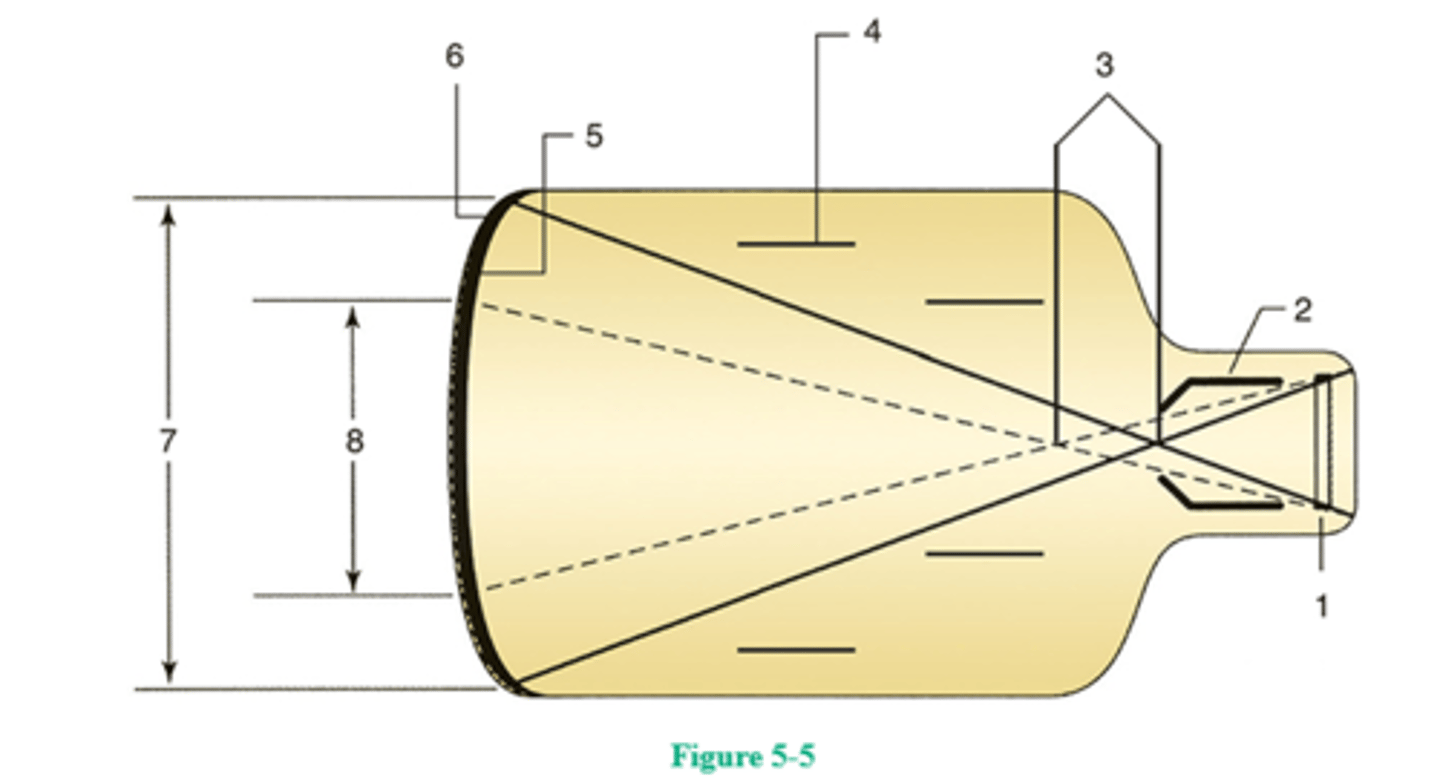
61. Which number in the Figure 5-5 represents magnification mode?
A. Number 1
B. Number 2
C. Number 7
D. Number 8
61. (D)
The image intensifier's input phosphor (number 6) receives the remnant radiation emerging from the patient and converts it into a fluorescent light image. Very close to the input phosphor, separated by a thin, transparent layer, is the photocathode (number 5). The photocathode is made of a photoemissive alloy, usually an antimony and cesium compound. The fluorescent light image strikes the photocathode and is converted to an electron image that is focused by the electrostatic lenses (number 4) to the output phosphor (number 1).
Dual- and triple-field image intensifiers are available that permit magnified viewing of fluoroscopic images. To achieve magnification, the voltage to the focusing lenses is increased and a smaller portion of the input phosphor is used (number 8), thereby resulting in a smaller FOV. Because minification gain is now decreased, the image is not as bright. The milliamperage is automatically increased to compensate for the loss in brightness when the image intensifier is switched to magnification mode. Entrance skin exposure (ESE) can increase dramatically as the FOV decreases (i.e., as magnification increases). The magnified output screen image has better resolution because there is less noise; increased milliamperage provides a greater number of x-ray photons, and contrast and resolution improve. The focal point (number 3) in the magnification mode is further away from the output phosphor (as a result of increased voltage applied to the focusing lenses) and therefore the output image is magnified.

62. Which number in the Figure 5-5 represents electrostatic focusing lens?
A. Number 5
B. Number 6
C. Number 4
D. Number 2
62. (C)
The image intensifier's input phosphor (number 6), usually made of cesium iodide, receives the remnant radiation emerging from the patient and converts it into a fluorescent light image. Very close to the input phosphor and separated by a thin transparent layer is the photocathode (number 5). The photocathode is made of a photoemissive alloy, usually an antimony and cesium compound. The fluorescent light image strikes the photocathode and is converted to an electron image that is focused by the electrostatic lenses (number 4), through the accelerating anode, to the output phosphor (number 1).
63. Advantages of CCDs over the use of television cameras in image intensification include which of the following?
1. Compact size
2. Improved resolution
3. Higher DQE
A. 1 only
B. 1 and 2 only
C. 2 and 3 only
D. 1, 2, and 3
63. (D)
CCDs have been used to replace the television camera associated with image intensification. They are much more compact than a television camera and can efficiently capture the fluoroscopic image. In comparison to television cameras, CCDs provide better resolution and contrast and have a higher DQE (detective quantum efficiency) and SNR (signal-to-noise ratio). CMOS efficiency has improved greatly over the past decade. Advantages of CMOS over CCDs include significantly less cost, greater speed, and much more energy efficiency (less power consumption). The CCD still provides somewhat better image quality.
64. Which of the following information is necessary to determine the maximum safe kilovoltage using the appropriate x-ray tube rating chart?
1. Milliamperage and exposure time
2. Focal spot size
3. Imaging system speed
A. 1 only
B. 1 and 2 only
C. 2 and 3 only
D. 1, 2, and 3
64. (B)
Given the milliamperage and exposure time, a radiographic rating chart enables the radiographer to determine the maximum safe kilovoltage for a particular exposure. Because the heat load an anode will safely accept varies with the size of the focal spot and the type of rectification, these variables must be identified. Each x-ray tube has its own radiographic rating chart. The speed of the imaging system has no impact on the use of a radiographic rating chart.
65. Spatial resolution in computed radiography increases as
1. monitor matrix size decreases
2. PSP crystal size decreases
3. laser beam size decreases
A. 1 only
B. 1 and 2 only
C. 2 and 3 only
D. 1, 2, and 3
65. (C)
Spatial resolution in CR is impacted by the size of the PSP, the size of the scanning laser beam, and monitor matrix size. High-resolution monitors (2-4 megapixels) are required for high-quality, high-resolution image display. The larger the matrix size, the better is the image resolution. Typical image matrix size (rows and columns) used in chest radiography is 2048 × 2048. Spatial resolution is measured in line pairs per millimeter (lp/mm). As matrix size is increased, there are more and smaller pixels in the matrix and, therefore, improved spatial resolution. Other factors contributing to image resolution are the size of the laser beam and the size of the PSP phosphors. Smaller phosphor size improves resolution—anything that causes an increase in light diffusion will result in a decrease in resolution. Smaller PSP phosphors permit less light diffusion. In addition, the scanning laser light must be of the correct intensity and size. A narrow laser beam is required for optimal resolution.
66. The voltage across the x-ray tube in three-phase equipment
1. drops to zero every 180°
2. is 87%-96% of the maximum value
3. is at nearly constant potential
A. 1 only
B. 2 only
C. 1 and 2 only
D. 2 and 3 only
66. (D)
With single-phase, full-wave-rectified equipment, the voltage is constantly changing from 0% to 100% of its maximum value. It drops to 0 every 180° (of the AC waveform), that is, there is 100% voltage ripple. With three-phase equipment, the voltage ripple is significantly smaller. Three-phase, six-pulse equipment has a 13% voltage ripple, and three-phase, 12-pulse equipment has a 3.5% ripple. Therefore, the voltage never falls below 87%-96.5% of its maximum value with three-phase equipment, and it closely approaches constant potential (direct current [DC]).
67. Which of the following would be appropriate IP front material(s)?
1. Tungsten
2. Magnesium
3. Bakelite
A. 1 only
B. 1 and 2 only
C. 2 and 3 only
D. 1, 2, and 3
67. (C)
The IP is used to house, support, and protect the PSP within the IP (cassette). The IP front should be made of a sturdy material with a low atomic number because attenuation of the remnant beam is undesirable. Bakelite (the forerunner of plastics these days) and magnesium (the lightest structural metal) are the materials used most commonly for cassette fronts. The high atomic number of tungsten makes it inappropriate as an IP front material.
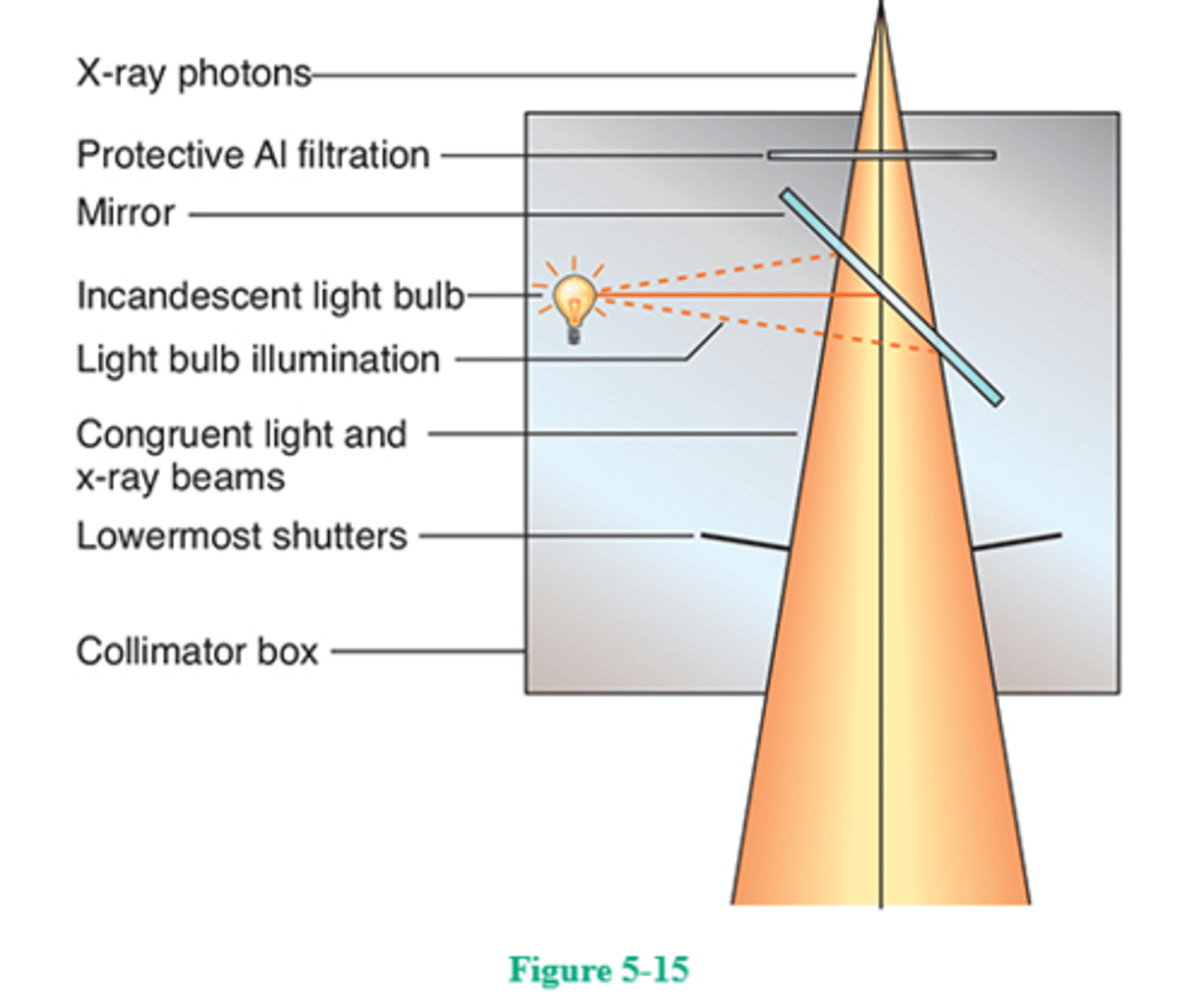
68. If the distance from the focal spot to the center of the collimator's mirror is 6 inches, what distance should the illuminator's light bulb be from the center of the mirror?
A. 3 inches
B. 6 inches
C. 9 inches
D. 12 inches
68. (B)
The collimator assembly includes a series of lead shutters, a mirror, and a light bulb (Fig. 5-15). The mirror and light bulb function to project the size, location, and center of the irradiated field. The bulb's emitted beam of light is deflected by a mirror placed at an angle of 45° in the path of the light beam. In order for the projected light beam to be the same size as the x-ray beam, the focal spot and the light bulb must be exactly the same distance from the center of the mirror.
69. The image intensifier's input phosphor generally is composed of
A. cesium iodide
B. zinc cadmium sulfide
C. gadolinium oxysulfide
D. calcium tungstate
69. (A)
The image intensifier's input phosphor receives the remnant beam from the patient and converts it to a fluorescent light image. To maintain resolution, the input phosphor is made of cesium iodide crystals. Cesium iodide is much more efficient in this conversion process than was the phosphor used previously, zinc cadmium sulfide. Calcium tungstate was one of the earliest phosphors used many years prior to the development of rare earth phosphors, such as gadolinium oxysulfide.
70. The essential function of an AEC is to
A. provide a brighter fluoroscopic image
B. automatically restrict the field size
C. terminate the x-ray exposure once the IR is correctly exposed
D. automatically increase or decrease incoming line voltages
70. (C)
AEC devices are used in equipment these days and serve to produce consistent and comparable radiographic results. In the most common type of AEC, an ionization chamber is located just beneath the tabletop above the IR. The part to be examined is centered to the AEC's sensor and imaged. When a predetermined quantity of ionization has occurred (equal to the correct receptor exposure), the x-ray exposure terminates automatically. The manual timer should always be used as a backup timer. In case of AEC malfunction, it would terminate the exposure, thus avoiding patient overexposure and x-ray tube overload. An image intensifier functions to provide a brighter fluoroscopic image, and positive beam limitation (PBL), or automatic collimation, serves to restrict the field size to the size of the cassette/IR used in the Bucky tray. The line-voltage compensator automatically adjusts the incoming line voltage to the x-ray machine to correct for any voltage drops or surges.
71. Grid interspace material can be made of
1. carbon fiber
2. aluminum
3. plastic fiber
A. 1 only
B. 1 and 2 only
C. 2 and 3 only
D. 1, 2, and 3
71. (C)
Grids are composed of alternating strips of lead and radiolucent interspace material. The interspace material is either aluminum or plastic fiber. Aluminum resists moisture, is sturdier, provides a "smoother" appearance with less visible grid lines, but requires a higher milliampere seconds value and therefore increases patient dose. Plastic fiber interspace material can be affected by moisture, resulting in warping. Carbon fiber is often used as image plate front material because of its durability and homogeneity.
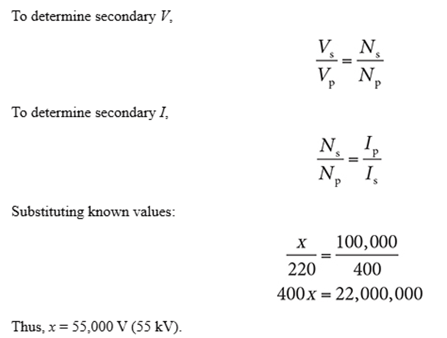
72. If the primary coil of a high-voltage transformer is supplied by 220 V and has 400 turns and the secondary coil has 100,000 turns, what is the voltage induced in the secondary coil?
A. 80 kV
B. 55 kV
C. 80 V
D. 55 V
72. (B)
The high-voltage, or step-up, transformer functions to increase voltage to the necessary kilovoltage. It decreases the amperage to milliamperage. The amount of increase or decrease depends on the transformer ratio, that is, the ratio of the number of turns in the primary coil to the number of turns in the secondary coil. The transformer law is as follows:
To determine secondary V,
Vs/Vp = Ns/Np
To determine secondary I,
Ns/Np = Ip/Is
Substituting known values:
X/220 = 100,000/400
400X = 22,000,000
Thus, x = 55,000 V (55 kV).
73. Which of the following circuit devices operate(s) on the principle of self-induction?
1. Autotransformer
2. Rectifiers
3. High-voltage transformer
A. 1 only
B. 1 and 2 only
C. 2 and 3 only
D. 1, 2, and 3
73. (A)
The principle of self-induction is an example of the second law of electromagnetics (Lenz's law), which states that an induced current within a conductive coil will oppose the direction of the current that induced it. It is important to note that self-induction is a characteristic of AC only. The fact that AC is constantly changing direction accounts for the opposing current set up in the coil. The autotransformer operates on the principle of self-induction and enables the radiographer to vary the kilovoltage. The high-voltage transformer operates on the principle of mutual induction. Rectifiers function to change alternating current to the unidirectional pulsating current required for efficient x-ray tube operation.
74. When the radiographer selects kilovoltage on the control panel, which device is adjusted?
A. Step-up transformer
B. Autotransformer
C. Filament circuit
D. Rectifier circuit
74. (B)
Because the high-voltage transformer has a fixed ratio, there must be a means of changing the voltage sent to its primary coil; otherwise, there would be a fixed kilovoltage. The autotransformer makes these changes possible. When kilovoltage is selected on the control panel, the radiographer actually is adjusting the autotransformer and selecting the amount of voltage to send to the high-voltage transformer to be stepped up (to kilovoltage). The filament circuit supplies the proper current and voltage to the x-ray tube filament for proper thermionic emission. The rectifier circuit is responsible for changing AC to unidirectional current.
75. The brightness level of the fluoroscopic image can vary with
1. milliamperage
2. kilovoltage
3. patient thickness
A. 1 only
B. 1 and 2 only
C. 1 and 3 only
D. 1, 2, and 3
75. (D)
The thicker and denser the anatomic part being studied, the less bright will be the fluoroscopic image. Both milliamperage and kilovoltage affect the fluoroscopic image in a way similar to the way in which they affect the radiographic image. For optimal contrast, especially taking patient dose into consideration, higher kilovoltage and lower milliamperage are generally preferred.
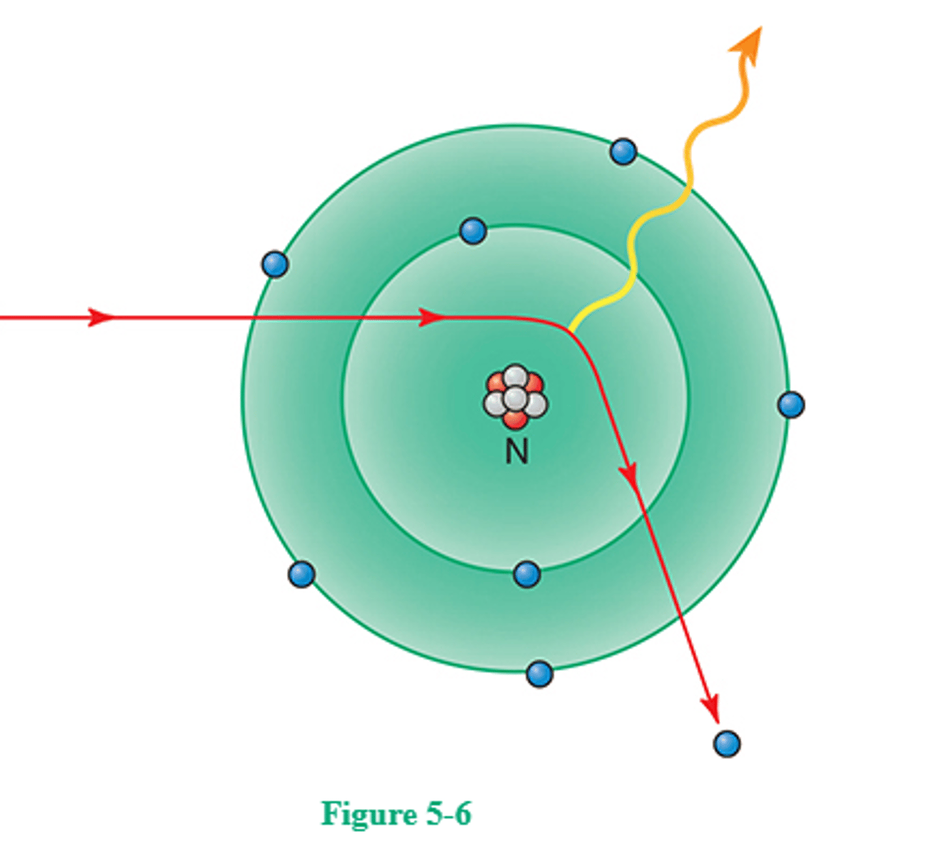
76. Which of the following does Figure 5-6 represent?
A. Compton scatter
B. Bremsstrahlung radiation
C. Photoelectric effect
D. Characteristic radiation
76. (B)
In Bremsstrahlung (Brems) or "braking" x-ray production, a high-speed electron, accelerated toward a tungsten atom, is attracted (and "braked," i.e., slowed down) by the positively charged nucleus and therefore is deflected from its original course with a resulting loss of kinetic energy. This energy loss re-emerges in the form of an x-ray photon. The electron might not give up all its kinetic energy in one such interaction; it might go on to have several more interactions deeper in the target, each time giving up an x-ray photon having less and less energy. This is one reason the x-ray beam is heterogeneous (i.e., has a spectrum of energies). Brems radiation comprises 70%-90% of the x-ray beam. The other type of x-ray production that occurs in the tungsten anode is characteristic radiation. In this case, a high-speed electron encounters the tungsten atom and ejects a K-shell electron, leaving a vacancy in the K shell. An electron from a shell above (e.g., the L shell) fills the vacancy and in doing so emits a K-characteristic ray. The energy of the characteristic ray is equal to the difference in energy between the K and L shells. K-characteristic x-rays from a tungsten-target x-ray tube have 69 keV of energy. Characteristic radiation comprises very little of the x-ray beam (15%-20%).
77. Guidelines regarding the use, care, and maintenance of protective lead aprons include (select three) which of the following?
A. They should be hung on a rack or draped over a bar when not in use
B. Federal law requires a minimum Pb equivalent of 0.25 mm
C. They should be folded carefully and stored safely when not in use
D. They should be x-rayed semiannually to detect any cracks
E. They protect from scatter and leakage radiation
77. (A, B, and E)
Lead aprons protect the radiation worker from leakage and scatter radiation; they do not protect from the primary beam. Federal law requires that lead aprons must have at least 0.25-mm lead equivalent protection. When not in use, they should be hung on a rack or draped over a bar. Folding lead aprons can cause creases and cracks in the protective material. Lead aprons must be x-rayed, either fluoroscoped or radiographed, annually to detect any cracks or other flaws.
78. A change in the size of the actual focal spot will cause a change in (select three)
A. detail sharpness
B. image contrast
C. effective focal spot size
D. spatial resolution
E. image brightness
78. (A, C, and D)
According to the line-focus principle, the effective focal spot size is always smaller than the actual focal spot size. If the large focal spot is selected, the effective focal spot size will be larger than if the small focal spot were selected. The smaller the focal spot size, the better the sharpness of image details and spatial resolution. Focal spot side has no effect on image contrast or brightness.
79. All of the following are associated with the anode, except
A. the line-focus principle
B. the heel effect
C. the focal track
D. thermionic emission
79. (D)
The rotating anode has a target (or focal spot) on its beveled edge that forms the target angle. As the anode rotates, it constantly turns a new face to the incoming electrons; this is the focal track. The portion of the focal track that is bombarded by electrons is the actual focal spot, and because of the target's angle, the effective or projected focal spot is always smaller (line-focus principle). The anode heel effect refers to decreased beam intensity at the anode end of the x-ray beam. The electrons impinging on the target have "boiled off" the cathode filament as a result of thermionic emission.
80. Which part of an induction motor is located within the x-ray tube glass envelope?
A. Filament
B. Focusing cup
C. Stator
D. Rotor
80. (D)
The anode is made to rotate through the use of an induction motor. An induction motor has two main parts, a stator and a rotor. The stator is the part located outside the glass envelope and consists of a series of electromagnets occupying positions around the stem of the anode. The stator's electromagnets are supplied with current, and the associated magnetic fields function to exert a drag or pull on the rotor within the glass envelope. The anode is a 2- to 5-inch diameter molybdenum or graphite disk with a beveled edge. The beveled surface has a focal track of tungsten-rhenium alloy. The anode rotates at about 3600 rpm (high-speed anode rotation is about 10,000 rpm) so that heat generated during x-ray production is evenly distributed over the entire track. Rotating anodes can withstand delivery of a greater amount of heat for a longer period of time than stationary anodes.
81. Regulations governing quality control of imaging equipment include (select three) which of the following?
A. The variation in x-ray intensity for a given exposure must not exceed 10%
B. Beam alignment must be accurate to within 2% of the SID
C. The control panel must indicate when the x-ray tube is energized
D. Linearity variation must not exceed 20% when testing mA stations
E. Total filtration must be at least 2.5-mm Al equivalent for 70 kV and above
81. (B, C, and E)
Quality control concerns the regular testing for accuracy of equipment and accessories. Safe and accurate equipment, and its use, helps to ensure patient safety. These guidelines state that beam alignment must be accurate to within 2% of the SID, the control panel must indicate when the x-ray tube is energized, total filtration must be at least 2.5-mm Al equivalent for 70 kV and above, the variation in x-ray intensity for a given exposure must not exceed 5%, and linearity variation must not exceed 10% when testing milliamperage stations.
82. As electrons impinge on the anode surface, less than 1% of their kinetic energy is changed to
A. x-rays
B. heat
C. gamma rays
D. recoil electrons
82. (A)
The vast majority of target interactions involve the incident electrons and outer-shell tungsten electrons. No ionization occurs, and the energy loss is reflected in heat generation. The production of x-rays is an amazingly inefficient process: More than 99% of the electrons' kinetic energy is changed to heat energy and less than 1% into x-ray photon energy. This presents a serious heat-buildup problem in the anode because heat production is directly proportional to tube current.
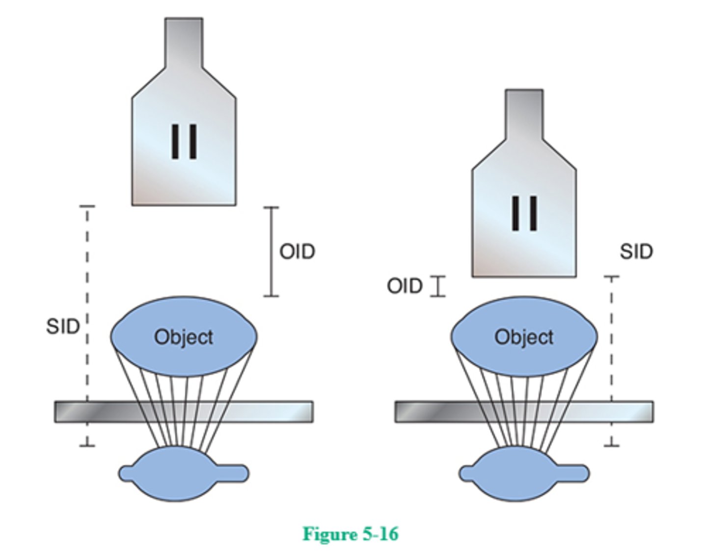
83. Moving the image intensifier closer to the patient during fluoroscopy
1. decreases the SID
2. decreases patient dose
3. improves image quality
A. 1 only
B. 1 and 2 only
C. 1 and 3 only
D. 1, 2, and 3
83. (D)
Moving the image intensifier closer to the patient during fluoroscopy reduces the distance between the x-ray tube (source) and the image intensifier (which is the image receptor in this case), that is, the SID. It follows that the distance between the part being imaged (object) and the image intensifier (IR), that is, the object-to-image-receptor distance (OID), is also reduced. The shorter OID produces less magnification and better image quality. As the SID is reduced, the intensity of the x-ray photons at the image intensifier's input phosphor increases, stimulating the automatic brightness control (ABC) to decrease the milliamperage and thereby decreasing patient dose (Fig. 5-16).
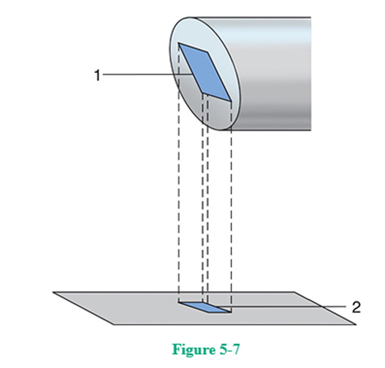
84. Figure 5-7 illustrates the
A. inverse-square law
B. line-focus principle
C. reciprocity law
D. anode heel effect
84. (B)
X-ray tube focal spots/targets are constructed according to the line-focus principle—the focal spot is angled (usually, 12°-17°) to the vertical. As the actual focal spot is projected downward, it is foreshortened; thus, the effective focal spot is always smaller than the actual focal spot. As it is projected toward the cathode end of the x-ray beam, the effective focal spot becomes larger and approaches its actual size. As it is projected toward the anode end, and foreshortening becomes more pronounced, the effective focal spot becomes smaller. Anode heel effect refers to the variation in x-ray beam intensity between the anode and cathode. Because of the anode angle, x-ray beam intensity is greater at the cathode end of the beam and less at the anode into the beam—as the x-ray beam attempts to diverge, it is absorbed by the "heel" of the anode at that end of the x-ray tube.
85. Although the stated focal spot size is measured directly under the actual focal spot, focal spot size actually varies along the length of the x-ray beam. At which portion of the x-ray beam is the effective focal spot the smallest?
A. At its outer edge
B. Along the path of the central ray
C. At the cathode end
D. At the anode end
85. (D)
X-ray tube targets are constructed according to the line-focus principle—the focal spot is angled (usually, 12°-17°) to the vertical. As the actual focal spot is projected downward, it is foreshortened; thus, the effective focal spot is always smaller than the actual focal spot. As it is projected toward the cathode end of the x-ray beam, the effective focal spot becomes larger and approaches its actual size. As it is projected toward the anode end, and foreshortening becomes more pronounced, the effective focal spot becomes smaller.
86. Which of the following x-ray circuit devices is located in the secondary/high-voltage portion of the x-ray circuit?
A. The timer
B. The kilovoltage meter
C. The milliamperage meter
D. The autotransformer
86. (C)
All circuit devices located before the primary coil of the high-voltage transformer are said to be on the primary or low-voltage side of the x-ray circuit. The timer, autotransformer, and (prereading) kilovoltage meter are all located in the low-voltage circuit. The milliampere meter, however, is connected at the midpoint of the secondary coil of the high-voltage transformer. When studying a diagram of the x-ray circuit, it will be noted that the milliampere meter is grounded at the midpoint of the secondary coil (where it is at zero potential). Therefore, it may be placed in the control panel safely.
87. Which of the following is/are associated with magnification fluoroscopy?
1. Higher patient dose than nonmagnification fluoroscopy
2. Higher voltage to the focusing lenses
3. Image intensifier focal point closer to the input phosphor
A. 1 only
B. 1 and 2 only
C. 2 and 3 only
D. 1, 2, and 3
87. (D)
The input phosphor of image intensifiers is usually made of cesium iodide. For each x-ray photon absorbed by cesium iodide, approximately 5000 light photons are emitted. As the light photons strike a photoemissive photocathode, a number of electrons are released from the photocathode and focused toward the output side of the image tube by voltage applied to the negatively charged electrostatic focusing lenses. The electrons are then accelerated through the neck of the tube, where they strike the small (0.5-1 inch) output phosphor that is mounted on a flat glass support. The entire assembly is enclosed within a 2- to 4-mm thick vacuum glass envelope. Remember that the image on the output phosphor is minified, brighter, and inverted (electron focusing causes image inversion).
Input screen diameters of 5-12 inches are available. Although smaller diameter input screens improve resolution, they do not permit a large FOV, that is, viewing of large patient areas.
Dual- and triple-field image intensifiers are available that permit magnified viewing of fluoroscopic images. To achieve magnification, the voltage to the focusing lenses is increased and a smaller portion of the input phosphor is used, thereby resulting in a smaller FOV. Because minification gain is now decreased, the image is not as bright. The milliamperage is automatically increased to compensate for the loss in brightness when the image intensifier is switched to magnification mode. Entrance skin exposure (ESE) can increase dramatically as the FOV decreases (i.e., as magnification increases).
As FOV decreases, magnification of the output screen image increases, there is less noise because increased milliamperage provides a greater number of x-ray photons, and contrast and resolution improve. The focal point in the magnification mode is further ......
88. Advantages of battery-powered mobile x-ray units include their
1. ability to store a large quantity of energy
2. ability to store energy for extended periods of time
3. ease of maneuverability
A. 1 only
B. 1 and 2 only
C. 2 and 3 only
D. 1, 2, and 3
88. (D)
There are two main types of mobile x-ray equipment—capacitor-discharge and battery-powered. Capacitor-discharge units are light, and therefore fairly easy to maneuver. Battery-powered mobile units, with their heavy-duty power sources, have become much lighter in weight and they have the advantage of being capable of storing a large milliampere seconds capacity for extended periods of time. These units frequently have a capacity of 10,000 mAs, with 12 h required for a full charge.
89. The device that receives the remnant beam, converts it into light, and then increases the brightness of that light is the
A. charge coupled device (CCD)
B. spot image device
C. image intensifier
D. television monitor
89. (C)
The visual apparatus that is responsible for visual acuity and contrast perception is the cones within the retina. Cones are also used for daylight vision. Therefore, the most desirable condition for fluoroscopic viewing is to have a bright enough image to permit cone (daylight) vision for better detail perception. The image intensifier accomplishes this. The intensified image is then transferred to a TV monitor for viewing. Cine and spot image devices can be used to record fluoroscopic events.
90. Off-focus, or extrafocal, radiation is minimized by
A. avoiding the use of very high kilovoltages
B. restricting the x-ray beam as close to its source as possible
C. using compression devices to reduce tissue thickness
D. avoiding extreme collimation
90. (B)
Off-focus, or extrafocal, radiation is produced as electrons strike metal surfaces other than the focal track and produce x-rays that emerge with the primary beam at a variety of angles. This radiation is responsible for indistinct images outside the collimated field. Mounting a pair of shutters as close to the source as possible minimizes off-focus radiation.
91. Which of the following factors contribute(s) to the efficient performance of a grid?
1. Grid ratio
2. Number of lead strips per inch
3. Amount of scatter transmitted through the grid
A. 1 only
B. 2 only
C. 1 and 2 only
D. 1, 2, and 3
91. (D)
Grid ratio is defined as the ratio of the height of the lead strips to the width of the interspace material; the higher the lead strips, the more scattered radiation they will trap and the greater is the grid's efficiency. The greater the number of lead strips per inch, the thinner and less visible they will be on the finished radiograph. The function of a grid is to absorb scattered radiation to improve radiographic contrast. The selectivity of a grid is determined by the amount of primary radiation transmitted through the grid divided by the amount of scattered radiation transmitted through the grid.
92. The AEC device operates on which of the following principles?
1. Delivery of the required exposure time
2. A parallel-plate ionization chamber charged by x-ray photons
3. Motion of magnetic fields inducing current in a conductor
A. 1 only
B. 2 only
C. 1 and 2 only
D. 1, 2, and 3
92. (C)
A parallel-plate ionization chamber is the most commonly used AEC. A radiolucent chamber of air is located beneath the patient (between the patient and the IR). As photons emerge from the patient, they enter the chamber and ionize the air within it. Once a predetermined charge has been reached, the exposure is terminated automatically. AEC determines exposure time; the radiographer must determine optimum kilovoltage and milliamperage. Motion of magnetic fields inducing current in a conductor refers to the principle of mutual induction.
93. The kilovoltage settings on radiographic equipment must be tested annually and must be accurate to within
A. ±2 kV
B. ±4 kV
C. ±6 kV
D. ±8 kV
93. (B)
Quality control refers to our equipment and its safe and accurate operation. Various components must be tested at specified intervals and test results must be within specified parameters. Any deviation from those parameters must be corrected. Examples of equipment components that are tested annually are the focal spot size, linearity, reproducibility, filtration, kilovoltage, and exposure time. Kilovoltage settings can most effectively be tested using an electronic kilovoltage meter; to meet required standards, the kilovoltage should be accurate to within ±4 kV.
Congruence is a term used to describe the relationship between the collimator light field and the actual x-ray field—they must be congruent (i.e., match) to within 2% of the SID. Collimators should be inspected and verified as accurate semiannually, that is, twice a year. Reproducibility testing should specify that radiation output be consistent to within ±5%.
94. If 92 kV and 15 mAs were used for a particular abdominal exposure with single-phase equipment, what milliampere seconds value would be required to produce a similar radiograph with three-phase, 12-pulse equipment?
A. 36
B. 24
C. 10
D. 7.5
94. (D)
Single-phase radiographic equipment is less efficient than three-phase equipment because it has a 100% voltage ripple. With three-phase equipment, voltage never drops to zero, and x-ray intensity is significantly greater. To produce similar receptor exposure, only two-thirds of the original milliampere seconds value would be used for three-phase, six-pulse equipment. With three-phase, 12-pulse equipment, the original milliampere seconds value would be cut in half (one-half of 15 mAs = 7.5).
95. Bone densitometry is often performed to
1. measure degree of bone (de)mineralization
2. evaluate the results of osteoporosis treatment/therapy
3. evaluate the condition of soft tissue adjacent to bone
A. 1 only
B. 1 and 2 only
C. 2 and 3 only
D. 1, 2, and 3
95. (B)
DXA imaging is used to evaluate bone mineral density (BMD). Bone densitometry (i.e., DXA) can be used to evaluate bone mineral content of the body, or part of it, to diagnose osteoporosis or to evaluate the effectiveness of treatments for osteoporosis. It is the most widely used method of bone densitometry—it is low-dose, precise, and uncomplicated to use/perform. DXA uses two photon energies—one for soft tissue and one for bone. Because bone is denser and attenuates x-ray photons more readily, their attenuation is calculated to represent the degree of bone density. Soft-tissue attenuation information is not used to measure bone density.
96. Required corrections made to "raw" digital image data that occur as a result of inherent flaws in the image acquisition system is called
A. preprocessing
B. postprocessing
C. windowing
D. leveling
96. (A)
Digital image acquisition has inherent system flaws. Corrections made to the "raw" digital images to repair these flaws is termed preprocessing (or acquisition processing). The inherent flaws are attributable to image receptor system elements and processor circuitry. Any later adjustments made by the operator or by equipment default settings are called postprocessing.
97. When using the smaller field in a dual-field image intensifier
1. the image is magnified
2. the image is brighter
3. a larger anatomic area is viewed
A. 1 only
B. 1 and 3 only
C. 2 and 3 only
D. 1, 2, and 3
97. (A)
When a dual-field image intensifier is switched to the smaller field, the electrostatic focusing lenses are given a greater charge to focus the electron image more tightly. The focal point, then, moves further from the output phosphor (the diameter of the electron image is, therefore, smaller as it reaches the output phosphor), and the brightness gain is somewhat diminished. Hence, the patient area viewed is somewhat smaller and is magnified. However, the minification gain has been reduced, and the image is somewhat less bright.
98. In Figure 5-8, what is the maximum safe milliamperage that may be used with a 0.05-s exposure and 120 kV, using the three-phase, 2.0-mm focal spot x-ray tube?
A. 300 mA
B. 400 mA
C. 500 mA
D. 600 mA
98. (D)
A radiographic rating chart enables the radiographer to determine the maximum safe milliamperage, exposure time, and kilovoltage for a given exposure using a particular x-ray tube. Because the heat load that an anode will safely accept varies with the size of the focal spot, type of rectification, and anode rotation, these variables must also be identified. Each x-ray tube has its own characteristics and its own rating chart. Find the correct chart for the three-phase, 2.0-mm focal spot x-ray tube. Locate 0.05 s on the horizontal (seconds) axis and follow it up to where it intersects with the 120-kV line on the vertical (kV) axis. They intersect just above the 700-mA curve, at approximately 680 mA. Thus, 600 mA is the maximum safe milliamperage for this particular group of exposure factors and x-ray tube.
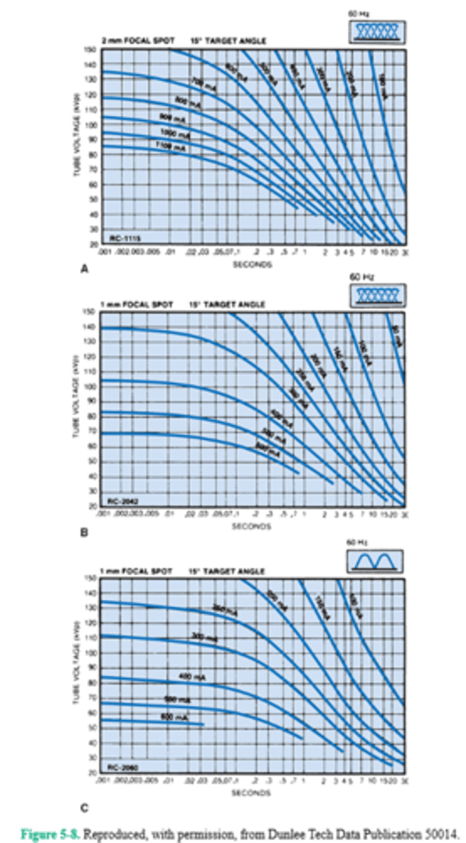
99. Referring to the anode cooling chart in Figure 5-9, if the anode is saturated with 300,000 heat units (HU), how long will the anode need to cool before another 100,000 HU can be safely applied?
A. 1 min
B. 2 min
C. 3 min
D. 4 min
99. (B)
Each x-ray exposure made by the radiographer produces hundreds or thousands of heat units at the target. If the examination requires several consecutive exposures, the potential for extreme heat load is increased. Just as each x-ray tube has its own radiographic rating chart, each tube also has its own anode cooling curve to describe its unique heating and cooling characteristics. An x-ray tube generally cools most rapidly during the first 2 min of nonuse. First, note that the tube is saturated with heat at 300,000 HU. In order for another 100,000 HU to be safely applied, the x-ray tube must first release 100,000 HU, which means that it has to cool down at least to 200,000 HU. Find the 200,000 HU point on the vertical axis and follow across to where it intersects with the cooling curve. It intersects at about the 2-min point.
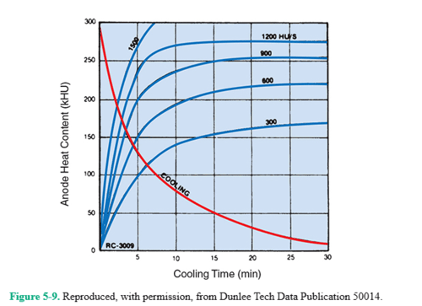
100. Which digital postprocessing operation removes image noise?
A. Edge enhancement
B. Smoothing
C. Aliasing
D. Windowing
100. (B)
Image smoothing (also called low-pass filtering) is used in digital image postprocessing to remove high-frequency noise, having a blurring effect. The reduction in noise also results in a reduction in contrast. Smoothing must not be used to remedy severe mottle, which represents underexposure.
Edge enhancement (also called high-pass filtering) removes low spatial frequencies and produces higher contrast and is particularly useful in digital vascular imaging.
Aliasing is a wraparound artifact that occurs when the spatial frequency is greater than the Nyquist frequency and the sampling occurs less than twice per cycle. This causes loss of information and a wraparound image, appearing as superimposed images out of alignment, and a moiré effect. The Nyquist theorem states that the sampling frequency must be greater than twice the bandwidth of the input signal in order for the image to be properly displayed.
Windowing is a postprocessing method of adjusting brightness and/or contrast. Window level adjusts the overall image brightness, whereas window width adjusts image contrast. Narrow window width provides higher contrast (short-scale contrast), whereas wide window width provides lower contrast (long-scale contrast).