SLR 16
1/5
There's no tags or description
Looks like no tags are added yet.
Name | Mastery | Learn | Test | Matching | Spaced | Call with Kai | Chat |
|---|
No analytics yet
Send a link to your students to track their progress
6 Terms
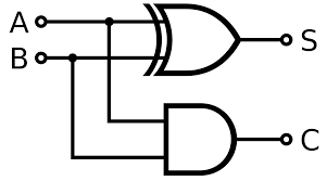
Half-Adder
takes 2 inputs and gives a two-bit output as the correct result of an addition of the two inputs
- Logic circuit for addition
- A · B = Carry (0+0 = 0, 1+0 = 0, 0+1 = 0, 1+1 = 1)
- A ⊕ B = Sum (0⊕0 = 0, 1⊕0 = 1, 0⊕ = 1, 1⊕1 = 0)
Half-Adder Image and Truth Table
A | + | B | = | C | S |
0 |
| 0 |
| 0 | 0 |
0 | 1 | 0 | 1 | ||
1 | 0 | 0 | 1 | ||
1 | 1 | 1 | 0 |
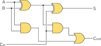
Full- Adder
combines two half adders to add three bits together, including the 2 inputs (A and B), and the carry bit C
- A ⊕ B = D
- A · B = E
- D ⊕ C = S
- D · C = F
- F + E = C
Full-Adder Image and Truth Table
A | + | B | + | C(in) | + | C(out) | S |
0 |
| 0 |
| 0 |
| 0 | 0 |
0 | 0 | 1 | 0 | 1 | |||
0 | 1 | 0 | 0 | 1 | |||
0 | 1 | 1 | 1 | 0 | |||
1 | 0 | 0 | 0 | 1 | |||
1 | 0 | 1 | 1 | 0 | |||
1 | 1 | 0 | 1 | 0 | |||
1 | 1 | 1 | 1 | 1 |
Multiple Full-Adders can be connected together
Need 1 full adder for each bit
Overflow errors occur when we run out of full adders
Will add A and B and output S and C (which is carried to the next full adder)
Next full adder will add A and B and C, and output S and C
D-type Flip-Flops
An elemental sequential logic circuit – store one bit and flip between 2 states, 0 and 1
Has 2 inputs – a control labelled D and a clock signal
The clock is another type of circuit which can change state at regular time intervals
D-type flip-flops are a positive edge-triggered flip-flop – output will only change when the clock is at a rising/ positive edge (beginning of a clock period)
When the clock is not at a positive edge, the input value is kept and does not change
The flip-flop circuit is important because it can be used as a memory cell to store the state of a bit