SLR 16
Name | Symbol | Diagram | Truth Table
| |||||||||||||||
NOT |
Q = Ā |
 |
| |||||||||||||||
OR |
Q = A + B |
 |
| |||||||||||||||
AND |
Q = A · B |  |
|
Name | Symbol | Diagram | Truth Table | |||||||||||||||
NAND
NOT (A AND B) | Q = A · B |  |
| |||||||||||||||
NOR
NOT (A OR B) |
Q = A + B | 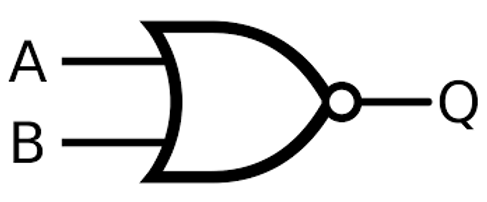 |
| |||||||||||||||
XOR
ONLY: 0 1 OR 1 0 | Q = A ⊕ B |  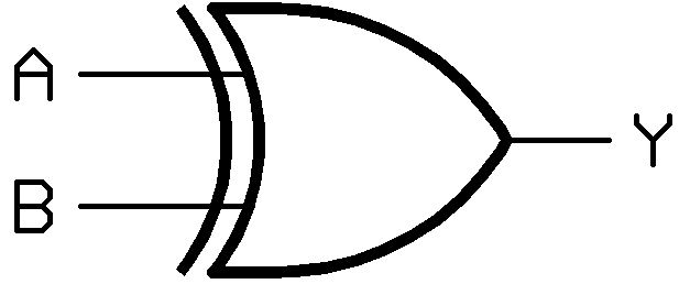 |
|
Appendix B:
Half-Adder: takes 2 inputs and gives a two-bit output as the correct result of an addition of the two inputs
- Logic circuit for addition
- A · B = Carry (0+0 = 0, 1+0 = 0, 0+1 = 0, 1+1 = 1)
- A ⊕ B = Sum (0⊕0 = 0, 1⊕0 = 1, 0⊕ = 1, 1⊕1 = 0)
A | + | B | = | C | S |
0 |
| 0 |
| 0 | 0 |
0 | 1 | 0 | 1 | ||
1 | 0 | 0 | 1 | ||
1 | 1 | 1 | 0 |
Full Adder: combines two half adders to add three bits together, including the 2 inputs (A and B), and the carry bit C
- A ⊕ B = D
- A · B = E
- D ⊕ C = S
- D · C = F
- F + E = C
A | + | B | + | C(in) | + | C(out) | S |
0 |
| 0 |
| 0 |
| 0 | 0 |
0 | 0 | 1 | 0 | 1 | |||
0 | 1 | 0 | 0 | 1 | |||
0 | 1 | 1 | 1 | 0 | |||
1 | 0 | 0 | 0 | 1 | |||
1 | 0 | 1 | 1 | 0 | |||
1 | 1 | 0 | 1 | 0 | |||
1 | 1 | 1 | 1 | 1 |
Multiple full adders can be connected together:
- Need 1 full adder for each bit
- Overflow errors occur when we run out of full adders
- Will add A and B and output S and C (which is carried to the next full adder)
- Next full adder will add A and B and C, and output S and C
D-type Flip-flops:
- An elemental sequential logic circuit – store one bit and flip between 2 states, 0 and 1
- Has 2 inputs – a control labelled D and a clock signal
- The clock is another type of circuit which can change state at regular time intervals
- D-type flip-flops are a positive edge-triggered flip-flop – output will only change when the clock is at a rising/ positive edge (beginning of a clock period)
- When the clock is not at a positive edge, the input value is kept and does not change
- The flip-flop circuit is important because it can be used as a memory cell to store the state of a bit
Boolean Algebra: p118
De Morgan’s Laws
- First law
o NOT (A OR B) == (NOT A) AND (NOT B)
- Second law
o NOT (A AND B) == (NOT A) OR (NOT B)
A | B | A OR B | NOT (A OR B) | = | NOT A | NOT B | (NOT A) AND (NOT B) |
0 | 0 | 0 | 1 |
| 1 | 1 | 1 |
0 | 1 | 1 | 0 | 1 | 0 | 0 | |
1 | 0 | 1 | 0 | 0 | 1 | 0 | |
1 | 1 | 1 | 0 | 0 | 0 | 0 |
A | B | A AND B | NOT (A AND B) | = | NOT A | NOT B | (NOT A) OR (NOT B) |
0 | 0 | 0 | 1 |
| 1 | 1 | 1 |
0 | 1 | 0 | 1 | 1 | 0 | 1 | |
1 | 0 | 0 | 1 | 0 | 1 | 1 | |
1 | 1 | 1 | 0 | 0 | 0 | 0 |
General Rules:
- AND GATES:
o X AND 0 = 0
o X AND 1 = X
o X AND X = X
o X AND NOT X = 0
- OR GATES:
o X OR 0 = X
o X OR 1 = 1
o X OR X = X
o X AND NOT X = 1
- NOT GATES
o NOT NOT X = X
o NOT NOT NOT X = NOT X
Commutative Rules:
- AND GATES:
o A AND B = B AND A
- OR GATES:
o A OR B = B OR A
Associative Rules:
- AND GATES:
o A AND (B AND C) = (A AND B) AND C
- OR GATES:
o A OR (B OR C) = (A OR B) OR C
Distributed Rules:
- AND GATES:
o A AND (B OR C) = A AND B OR A AND C
- OR GATES:
o A OR BC = (A OR B) AND (A OR C)
Absorption Rules: