MCAT Physics and Math - Light and Optics
1/68
Earn XP
Description and Tags
470
Name | Mastery | Learn | Test | Matching | Spaced | Call with Kai |
|---|
No analytics yet
Send a link to your students to track their progress
69 Terms
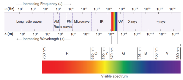
electromagnetic spectrum
describes the full range of frequencies and wavelengths of electromagnetic waves
wavelengths
units: mm (10–3 m), μm (10–6 m), nm (10–9 m), and Å (ångström, 10–10 m)
radio waves
long wavelength, low frequency, low energy
109–1 m
microwaves
1 m–1 mm
infrared
1 mm–700 nm
visible light
only part of the spectrum that is perceived as light by the human eye
700–400 nm (→ ROY G BIV)
ultraviolet
400–50 nm
X-rays
50–10–2 nm
gamma rays
short wavelength, high frequency, high energy
<10–2 nm
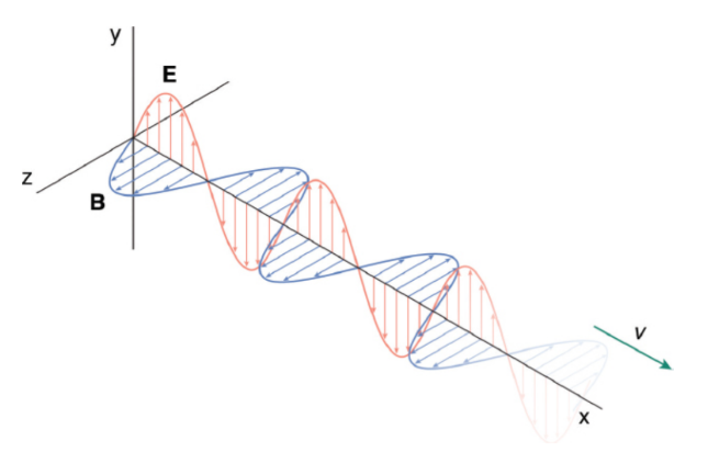
Electromagnetic waves
transverse waves because the oscillating electric and magnetic field vectors are perpendicular to the direction of propagation and to each other
speed of light (c)
all electromagnetic waves travel at the same speed
3.00 × 10⁸ m/s
c = fλ
where c is the speed of light in a vacuum and, to a first approximation, also in air, f is the frequency, and λ is the wavelength
blackbody
ideal absorber of all wavelengths of light, which would appear completely black if it were at a lower temperature than its surroundings
color of an object
dependent on the color of light that it reflects/does not absorb
opponent process theory
white = reflects all
balck = absorbs all
rectilinear propagation
light travels through a homogeneous medium in a straight line
Geometrical optics
explains reflection and refraction, as well as the applications of mirrors and lenses
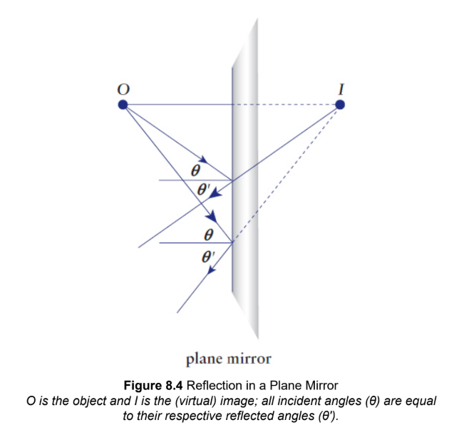
Reflection
rebounding of incident light waves at the boundary of a medium; not absorbed into the second medium; rather, they bounce off of the boundary and travel back through the first medium
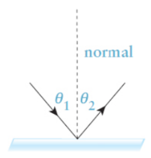
law of reflection
θ1 = θ2
where θ1 is the incident angle and θ2 is the reflected angle, both measured from the normal
normal
line drawn perpendicular to the boundary of a medium
real mirror images
the light actually converges at the position of the image; the ability of the image to be projected onto a screen
virtual mirror images
the light only appears to be coming from the position of the image but does not actually converge there
plane mirrors
flat reflective surfaces; cause neither convergence nor divergence of reflected light rays; always create virtual images; same distance ‘behind’ as in front; conceptualized as spherical mirrors with an infinite radius of curvature
i = –o
r = f = ∞
Spherical mirrors
mirror can be considered a spherical cap or dome taken from a much larger spherically shaped mirror; associated center of curvature (C) and a radius of curvature (r)
center of curvature (C)
point on the optical axis located at a distance equal to the radius of curvature from the vertex of the mirror; center of the spherically shaped mirror if it were a complete sphere
radius of curvature (r)
distance of actual mirrored surface from center of curvature
concave
inside of a sphere to its surface; ‘inward’ curve
convex
outside the sphere; ‘outward’ curve
concave/converging mirror
center of curvature and the radius of curvature are located in front of the mirror; cause parallel incident light rays to converge
convex/diverging mirror
center of curvature and the radius of curvature are behind the mirror; cause parallel incident light rays to diverge
focal length (f)
distance between the focal point (F) and the mirror
f = r/2
where the radius of curvature (r) is the distance between C and the mirror
Key Variables in Miror Optics
1/f = 1/o + 1/i = 2/r
focal length
object distance
image distance
radius of curvature
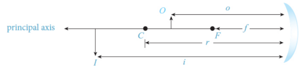
image distance
image has a positive distance (i > 0), real image - in front of mirror
image has a negative distance (i < 0), virtual image - behin dmirror
magnification (m)
dimensionless value that is the ratio of the image distance to the object distance; ratio of the size of the image to the size of the object
negative signifies an inverted image, while a positive value signifies an upright image
|m| < 1, the image is smaller than the object (reduced); |m| > 1, the image is larger than the object (enlarged)
m = i/o
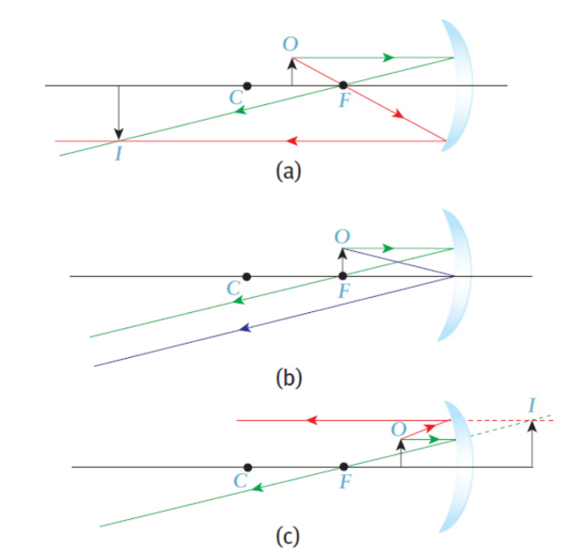
ray diagram
useful for getting an approximation of where an image is; real vs. virtual, inverted vs. upright, and magnified vs. reduced
Ray parallel to axis → reflects back through focal point
Ray through focal point → reflects back parallel to axis
Ray to center of mirror → reflects back at same angle relative to normal
axis
the normal passing through the center of the mirror
focal point (F)
object at this point no image is formed because the reflected light rays are parallel to each other
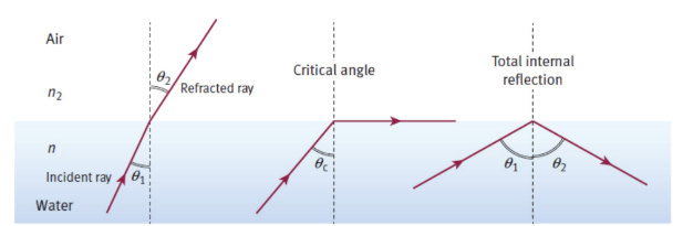
Refraction
bending of light as it passes from one medium to another and changes speed
Snell’s Law
n1 sin θ1 = n2 sin θ2
where n1 and θ1 refer to the medium from which the light is coming and n2 and θ2 refer to the medium into which the light is entering
when light enters a medium with a higher index of refraction (n2 > n1), it bends toward the normal (sin θ2 < sin θ1; therefore, θ2 < θ1)
when light travels into a medium where the index of refraction is smaller (n2 < n1), the light will bend away from the normal (sin θ2 > sin θ1; therefore, θ2 > θ1).
speed of light in medium
n = c/v
where c is the speed of light in a vacuum, ν is the speed of light in the medium, and n is the index of refraction of the medium
index of refraction (n)
dimensionless quantity affects speed of light through specific medium
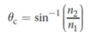
critical angle (θc)
As the incident angle is increased, special incident angle is reached, for which the refracted angle θ2 equals 90 degrees
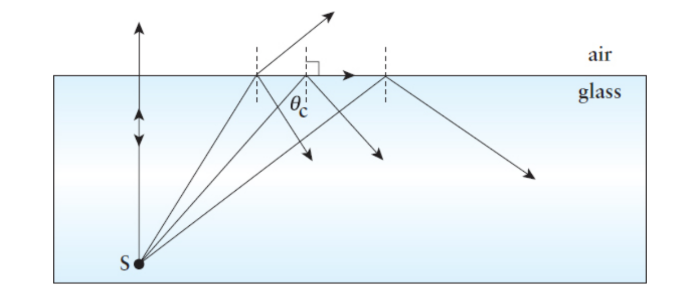
Total internal reflection
phenomenon in which all the light incident on a boundary is reflected back into the original material, results with any angle of incidence greater than the critical angle, θc
lenses
refract light with two surfaces; two focal points, one on each side
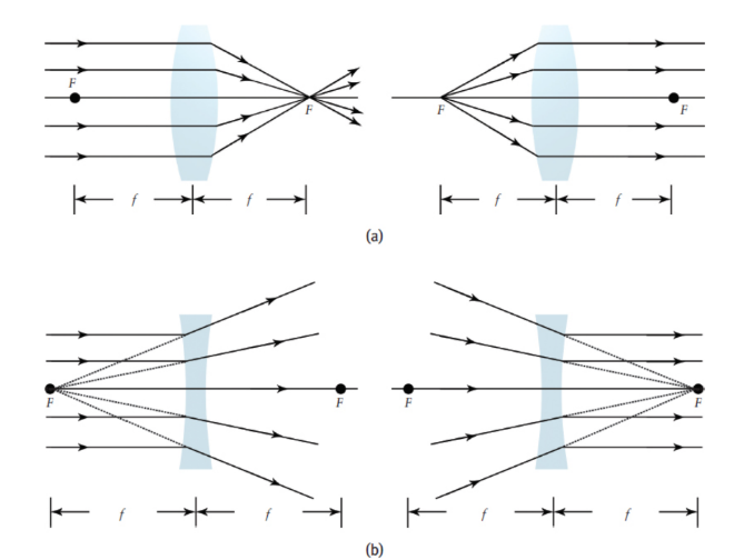
converging lens
thicker at the center
farsighted
diverging lens
thinner at the center
nearsighted
Key Variables in Lens Optics
1/f = 1/o + 1/i
m= -i/o
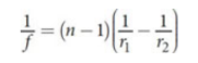
lensmaker’s equation
non negligible thick lenses
where n is the index of refraction of the lens material, r1 is the radius of curvature of the first lens surface, and r2 is the radius of curvature of the second lens surface
lens ray diagram
Ray parallel to axis → refracts through focal point of front face of the lens
Ray through or toward focal point before reaching lens → refracts parallel to axis
Ray to center of lens → continues straight through with no refraction
power (P)
P= 1/f
where f (the focal length) is in meters
measured in diopters
hyperopia
farsightedness
myopia
nearsightedness
Bifocal lenses
corrective lenses that have two distinct regions; one that causes convergence of light to correct for farsightedness (hyperopia) and a second that causes divergence of light to correct for nearsightedness (myopia)
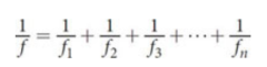
Lenses in contact
series of lenses with negligible distances between them.
Power is additive
magnification is mulltiplicative
aberrations
visual errors
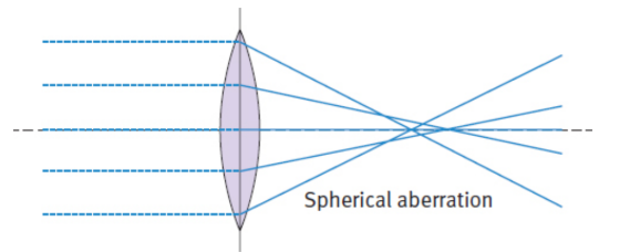
Spherical aberration
blurring of the periphery of an image as a result of inadequate reflection of parallel beams at the edge of a mirror or inadequate refraction of parallel beams at the edge of a lens
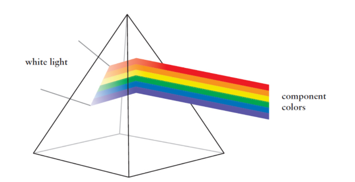
dispersion
various wavelengths of light separate from each other
ex. prism
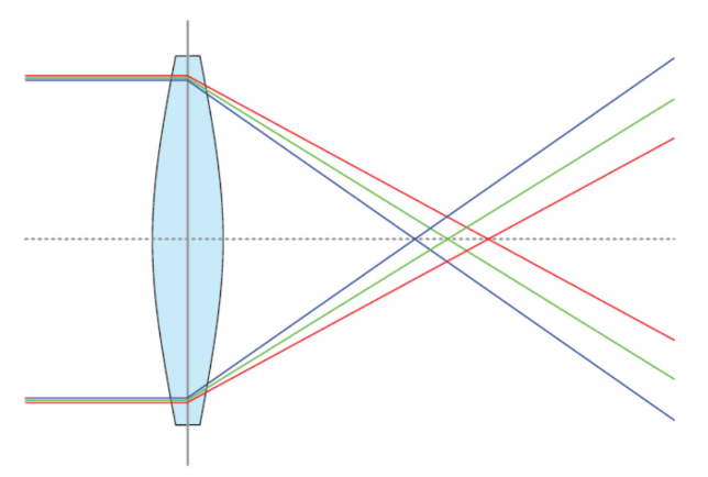
Chromatic aberration
dispersive effect within a spherical lens; rainbow halo around images
Diffraction
spreading out of light as it passes through a narrow opening or around an obstacle
Interference
between diffracted light rays lead to characteristic fringes in slit–lens and double-slit systems; displacements of the waves add together
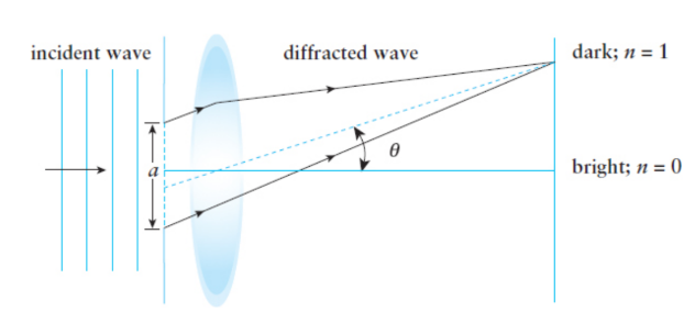
Single Slit difraction
When light passes through a narrow opening (an opening with a size that is on the order of light wavelengths), the light waves seem to spread out (diffract)
Slit–Lens System
bright central fringe with alternating dark and bright fringes on each side; central bright fringe (maximum) is twice as wide as the bright fringes on the sides; as the slit becomes narrower, the central maximum becomes wider; dark fringes (minima) is given by a sin θ = nλ
Multiple Slits
famous double-slit experiment, Thomas Young showed that the diffracted rays of light emerging from two parallel slits can interfere with one another; light as a wave
constructive interference between the two light waves appear as bright fringes (maxima); light waves interfere destructively, dark fringes (minima) (d sin θ = (n + 1/2)λ)
where d is the distance between the two slits, θ is the angle between the line drawn from the midpoint between the two slits to the dark fringe and the normal, n is an integer indicating the number of the fringe, and λ is the wavelength of the incident wave
Diffraction gratings
multiple slits arranged in patterns; can create colorful patterns similar to a prism
ex. grooves on a CD or DVD
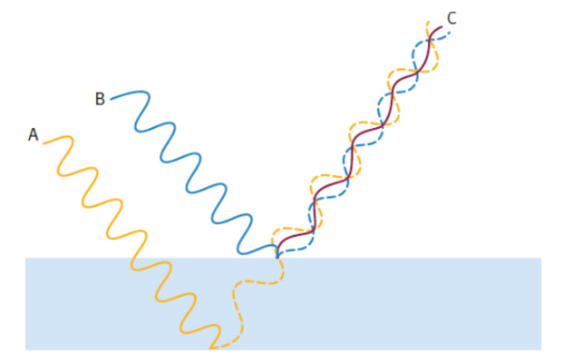
thin film diffraction
light waves reflecting off the external surface of the film interfere with light waves reflecting off the internal surface of the film; interference here is not between diffracted rays, but between reflected rays
ex. soap bubbles or oil puddles in wet parking lots
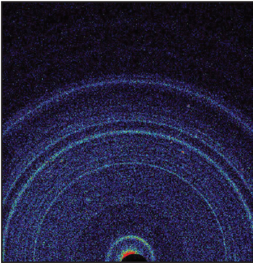
X-Ray Diffraction
bending of light rays to create a model of molecules; complex two-dimensional image.
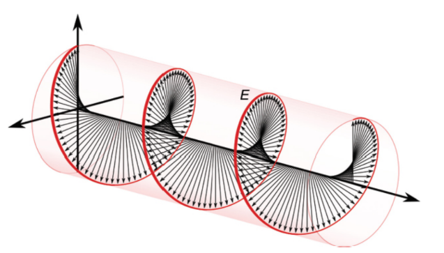
Plane-polarized (or linearly polarized) light
light in which the electric fields of all the waves are oriented in the same direction, electric field vectors are parallel
optical activity
causes plane-polarized light to rotate clockwise or counterclockwise by a given number of degrees relative to its concentration due to the presence of chiral centers
specific rotation
rotate clockwise or counterclockwise by a given number of degrees relative to its concentration
polarizers
allow only light with an electric field pointing in a particular direction to pass through
second polarizer is turned so that its axis is perpendicular, no light gets through at all
Circular Polarization
rarely seen natural phenomenon that results from the interaction of light with certain pigments or highly specialized filters; uniform amplitude but a continuously changing direction