CHE 352 Exam 1
 Call Kai
 Learn
Learn Practice Test
 Spaced Repetition
 Match
Match Flashcards
 Knowt Play
1/39

There's no tags or description
Looks like no tags are added yet.
Name | Mastery | Learn | Test | Matching | Spaced | Call with Kai | Chat |
|---|
No analytics yet
Send a link to your students to track their progress
40 Terms
electric signal
dashed line
flow of fluid
solid line
pneumatic signal
solid line with 2 dashes in it
communication signal (to DCS)
line with circles in it
FC or arrow down
fail closed
FO or arrow up
fail open
closed
filled in indicates a control valve is normally…
analysis
A (first letter)
flow rate
F (first letter)
current
I (first letter)
level
L (first letter)
pressure
P (first letter)
speed
S (first letter)
temperature
T (first letter)
alarm
A (second letter)
control
C (second letter)
element
E (second letter)
high
H (second letter)
indicate
I (second letter)
low
L (second letter)
record
R (second letter)
switch
S (second letter)
transmitter
T (second letter)
sensor —> transmitter —> controller —> actuator
feedback control scheme
sensor —> transmitter —> calculation block —> actuator (applied to two different variables (i.e. temperature and flow rate) of two different streams)
feedforward control scheme
feedback control scheme
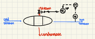
feedforward control scheme
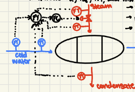
feedforward with trim control scheme
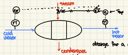
sensor —> transmitter —> proactive response block —> summing junction —> actuator (second stream to summing junction: sensor —> transmitter —> controller —> summing junction)
feedforward with trim control scheme
3-15 psig
pneumatic signal range
4-20 mA
electrical signal range
I/P transducer
converts signal from current to pressure (electrical to pneumatic)
spring and diaphragm, solenoid, motor
3 types of actuators
valve body
fluid ports, valve plug, valve stem
valve actuator
physically moves the resistor
spring and diaphragm control valve
pneumatic signal exerts pressure on diaphragm, pushes spring down and moves restrictor
solenoid control valve
current to coil generates magnetic field to move the restrictor downward
motor control valve
gear motor attached to valve stem receives a DC control signal from servo amp to move the restrictor to the desired position
I/P transducer explained
current is applied to electromagnet, as current changes, magnetism increases or decreases which affects the position of the beam in relationship to the nozzle to create changes in nozzle pressure
valve positioners explained
a pneumatic control signal is sent to a bellows to expand and act on a beam which pivots and moves a flapper in relation to a nozzle to create changes in nozzle pressure