Static Equilibrium
1/40
Earn XP
Description and Tags
MEE1004 - Mechanics of Materials 1. Week 14
Name | Mastery | Learn | Test | Matching | Spaced |
|---|
No study sessions yet.
41 Terms
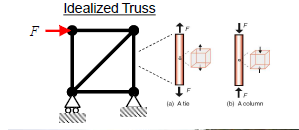
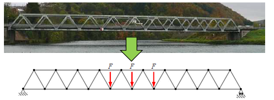
Truss structures
Members subjected to tensile / compressive forces.
Material subjected to axial stress.
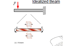
Beam structures
Members subjected to shear forces and bending moments.
Material subjected to bending stress.
Shaft structures
Members are subjected to torques.
Materials subjected to torsional shear stress.
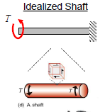
Torque
Moments about longitudinal axis.
Structural Idealisation
The process of making simplifying assumptions in order to facilitate a basic analysis.
Standard symbols
Used to represent different types of supports, based on:
The types displacement they allow, and
The corresponding reaction forces that develop.
Other word for moment
Torque.
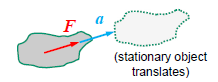
Newton’s Second Law
Linear acceleration (a) of an object of mass m is proportional to net force (F) acting upon it:
F = ma
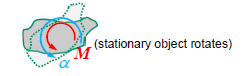
Angular acceleration equation
Angular acceleration (α) of an object with mass moment of inertia I is proportional to the net moment (M) acting upon it:
M = Iα
Moment
The turning effect of a force.
When forces tend to cause a rotation, they are exerting a moment. / Moments are the cause of a change in rotation.
Moments equation
Moment of a force = Force x perpendicular distance
M = Fd
Moments unit
Newton metre (Nm)
Distance is the moment equation is termed
The moment arm.
Moments sign convention
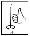
In accordance with the right hand rule, a moment that would tend to cause a counter-clockwise rotation is considered positive.
Right Hand Rule
Hold hand over point A.
Curl finger of your right hand in the direction of rotation.
Thumbs up = +M (pos.)
Thumbs down = -M (neg.)
Force couple
A system of two equal and opposite forces with different lines of action.
Concentrated moment
The equivalent force system for a force couple. It exerts the same about any point.
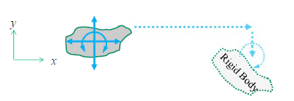
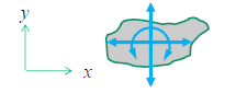
Degrees of Freedom
A rigid body has three possible degrees of freedom with respect to motion in two dimensions (three independent ways that the motion of a rigid body can change by accelerating).
Three degrees of freedom
Horizontal acceleration (x-direction),
Vertical acceleration (y-direction),
Angular acceleration (rotation in the x-y plane (z plane))
Rigid body
An object that cannot change shape(i.e. a solid object that we assume does not deform).
Conditions for Static Equilibrium (2-D)
There are three conditions for static equilibrium of a rigid body in two dimensions (in an x-y plane):
ΣFx = 0 ( the sum of all forces in the x-direction is zero). Therefore there is no acceleration in the x-direction.
ΣFy = 0 (the sum of all forces in the y-direction is zero). Therefore, there is no acceleration in the y-direction.
Σ(Mz)any point = 0 (the sum of all moments in the z-direction about any point is zero). Therefore, there is no rotation about the z-axis (in the x-y plane).
These conditions can be used to calculate up to three unknown forces / moments acting on an object that is in equilibrium (because we can write these three equations).
Free-Body Diagram
A sketch of an isolated objected with its surrounding objects replaced by the forces and / or moments that they exert on the isolated object.
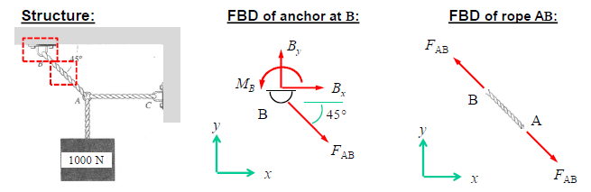
In a free-body diagram, when deciding what forces / moments being removed might exert
Consider which degrees of freedom are constrained by the portion removed.
Translation resisted in a given direction - there is a reaction force in that direction.
Rotation resisted about a given axis - there is a reaction moment about that axis.
Equal and opposite forces / moments are always exerted back on the elements that are removed from a FBD.
Essential components of FBD
Appropriate identification of the isolated object.
A coordinate system.
Any applied loads.
Reactions from any points of contact with bodies that were removed.
Indicate the assumed direction of all forces / moments with an arrow.
Any necessary information about geometry (i.e. angles).
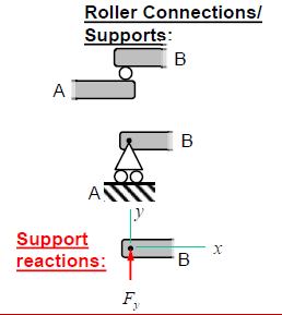
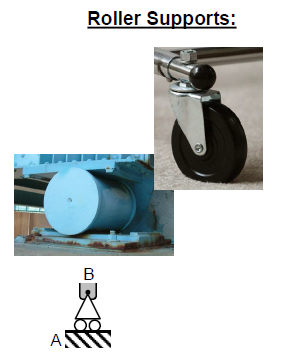
Roller connection / supports in a FBD
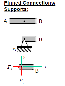
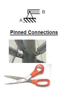
Pinned connections / supports in a FBD
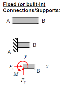
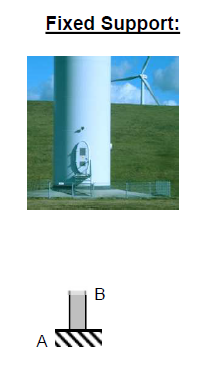
Fixed (or built-in) connections / supports in a FBD
Roller supports
Pinned connections
Fixed supports
Types of equilibrium
Static and dynamic.
In both cases, there must be a balance of forces acting on the object.
Static equilibrium
Occurs when an object is at rest.
Dynamic equailibrium
Occurs when an object is moving with a constant velocity.
Conditions of equilibrium
The net force acting on the object must be zero,
The net moment acting on the object must be zero.
Representing forces in a FBD
Forces are represented using arrows.
The direction of the arrows represents the direction of the force.
The length of the arrows depicts the magnitude of the force.
Common forces represented in a FBD
Weight, normal force, tension, friction and applied force.
Weight
The force of gravity acting on the object, typically represented by an arrow pointing downward. N
Normal force
The force between two objects when they come in contact with each other. This force acts in the opposite direction to the weight of the object.
Tension
Represented by an arrow pointing away from the object in the direction of the force.
Friction
The force that resists sliding between surfaces.
Applied force
The force applied to the object by an external agent, such as a push or a pull. Represented by an arrow pointing in the direction of the force.