EUV mirror actuation
 Call Kai
 Learn
Learn Practice Test
 Spaced Repetition
 Match
Match Flashcards
 Knowt Play
1/11

There's no tags or description
Looks like no tags are added yet.
Name | Mastery | Learn | Test | Matching | Spaced | Call with Kai | Chat |
|---|
No analytics yet
Send a link to your students to track their progress
12 Terms
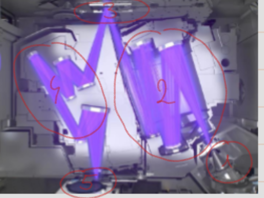
light source
illumination optics
image to be copied
projection optics
wafer
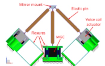
How many attachment points are there? How many actuators? How does the elastic pin workd?
There are 3 attachment points - each point has 2 actuators.
The elastic pin is a flexure type connector that constraing only 1 DOF along it s own axis to avoid play/hysteresis, so each actuator pair prescribes 2 DOF.
The goal of the EUV mirror is to isolate the mirror from base vibrations. How did they achieve it? Where was the problem?
The controller was used to control the mirror positions; however if the base vibrations were lower than the f_controller the actuator would effectively attenuate the vibrations and if the base vibrations were above the f_controller, the controller would prove ineffective.
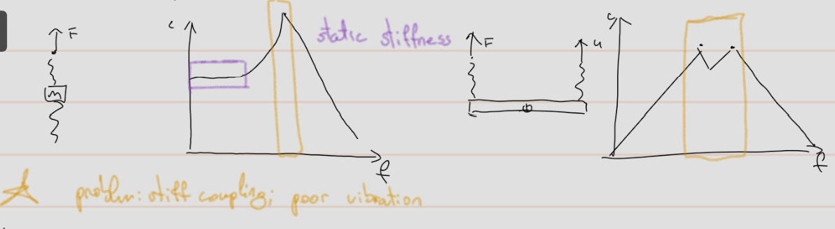
It lead to use of the dynamic stiffness.
Descrie dynamic stiffness.
Regular stiffness: c=F/u, and dynamic is (c1c2)/(ms²+c1+c2).
It can be described as a mass connected through two springs on each side.
What are the two types of electromagnetic forces?
Lorentz forces = force on charged particle moving in a magnetic field
reluctance force = magnetic attraction of iron
What are the types of actuators considered for this topic?
Lorentz actuator
reluctance actuator
hybrid reluctance actuator = bias flux present
Why was the hybrid reluctance actuator chosen in the end?
Whilst both hybrid and Lorentz have a linear steepness (S=F²/P), the hybrid has a higher steepness to mass ration and a low moving mass is better and the hybrid has the negative stiffness.
What is the trade-off and the reason why the voice coil actuator needed to change? Explain.
The voice-coil actuator is a moving magnet type. In the end, we needed low stiffness in drive direction and high eigenfrequency in the other direction. So, it was replaced with hybrid actuator for lower moving mass, stiffer moving guid and equal stiffness in the drive direction. The negative stiffness of the actuator can compensate straight guide stiffness in drive direction, adding negative stiffness to compensat the positive one.
To add, by using the hybrid actuator the number of eigenfrequency reduced from 4 to 2, allowing for easier implementation of damping.
== low stiffness in drive direction and high eigenfrequency in other direction
Explain further in detail how were the positive and negative stiffness used to cancel each other out.
Positive stiffness is linear, but negative isa non constant concave due to position dependent force, so negative stiffness was linearized.
Linearization was achieved by increasing the gap. That resulted in steepness decrease and was ficed by increasing the bias flux and largening the magnet width.
For the conceptual design of the coil. How was it achieved?
By maximizing the coil area and minimizng the coil length.
How was symmetry created in the system design?
Symmetric design includes two things:
static force is balance
the actuation force is through the center of the pin
A hollow tube was added: straight guide was made outside of the magnetic joke and pin length was increased in order to reduce parasitic stiffness.
Some stiffness adjusments were required. Possible adjusments were:
positive stiffness - flexure thickness
negative stiffness - magnet strength and air gap
The chose approach: adjusment of the bias flux by inserting a plate (magnet could only be weakend by it, so a slightly magner was used)
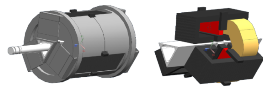
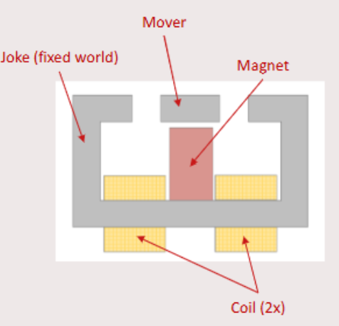
Left: white - pin, gray - housing and flexures
Right: white - mover tube, yellow - coils, red - magnet, black, stators + adjustment plate + movers