Engine Part Identification
 Call Kai
 Learn
Learn Practice Test
 Spaced Repetition
 Match
Match Flashcards
 Knowt Play
1/19

There's no tags or description
Looks like no tags are added yet.
Name | Mastery | Learn | Test | Matching | Spaced | Call with Kai | Chat |
|---|
No analytics yet
Send a link to your students to track their progress
20 Terms
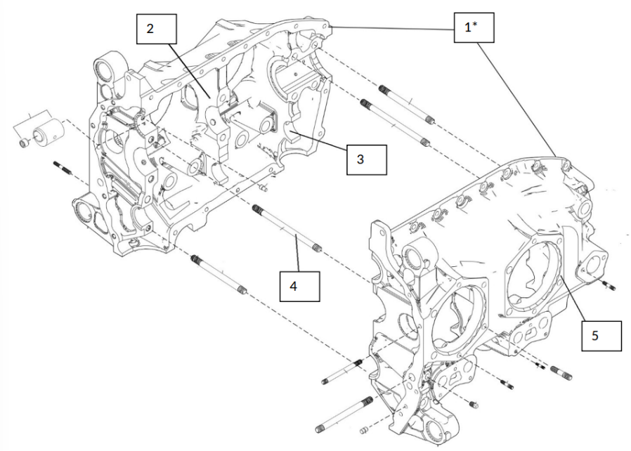
Identify These Parts (List 1-5)
Crankcase assembly — The core of a reciprocating engine. It contains the engine’s internal parts, provides attachment points for the cylinders and accessories, and provides a tight enclosure for lubricating oil.
Transverse web — Webs cast directly into the crankcase parallel to its longitudinal axis. They support the crankshaft, add strength, and form an integral part of the crankcase structure.
Camshaft boss — A set of bosses cast into the crankcase that support the camshaft and its bearing journals.
Crankcase through bolt — Through-bolts are typically used around the crankshaft-bearing areas to hold the crankcase halves together.
Cylinder mounting pad — The smooth, machined surface on the crankcase where a cylinder mounts.
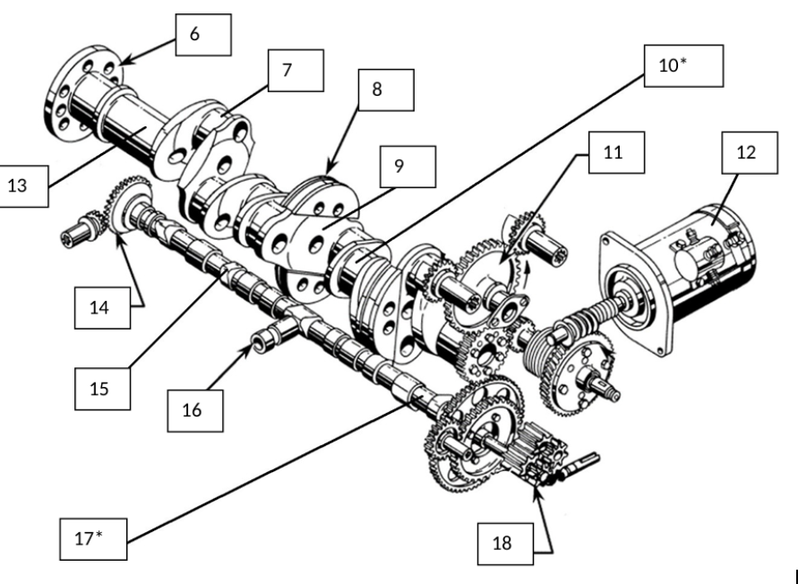
Identify These Parts (List 6-10)
Propeller flange — On a flanged propeller shaft, the crankshaft has a flat flange on its end and the propeller is bolted directly to the flange.
Rod journal / crankpin — Located at specific points along the crankshaft and offset from the main-bearing journal. It provides the attachment point for the connecting rod. Crankpins are also called throws, crank throws, and connecting-rod bearing journals.
Counterweight — Used to help balance the crankshaft. A movable counterweight used as a dynamic damper is attached to a crank cheek and oscillates to absorb vibration caused by power impulses.
Crankshaft cheek / crank cheek — Connects the crankpins to one another and to the crankshaft main journals. Some cheeks also provide attachment points for counterweights and contain oil passages between the main journal and crankpin.
Crankshaft — Receives the linear power pulse from the piston through the connecting rod and changes it into rotary motion to turn the propeller.
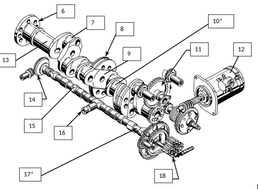
Identify These Parts (List 11-15)
Magneto drive gear — No separate definition is given in the provided textbook pages. The book states generally that the accessory-section gear train drives engine accessories, including magnetos.
Starter motor — No separate definition is given in the provided textbook pages. Starters are listed as possible accessories mounted to the accessory section.
Main journal — Main-bearing journals support the crankshaft as it rotates, absorb operational loads, and transmit stress from the crankshaft to the crankcase.
Governor bevel drive gear — No separate definition of this specific gear is given. The book states that bevel gears in the accessory section handle lighter loads and accommodate short drive shafts for accessories.
Camshaft lobe / cam lobe — A raised portion of the camshaft that transforms the camshaft’s rotary motion into linear motion. The shape of the cam determines how far a valve opens and how long it remains open.

Identify These Parts (List 16-18)
Governor bevel driven gear — No separate definition of this specific gear is given in the provided textbook pages.
Camshaft — A round shaft with a series of cams or lobes that transforms rotary motion into the linear motion required to operate the valves. In a four-stroke opposed engine, it rotates at one-half crankshaft speed.
Oil-pump and scavenge-pump gears — No separate definitions are given in the provided textbook pages.
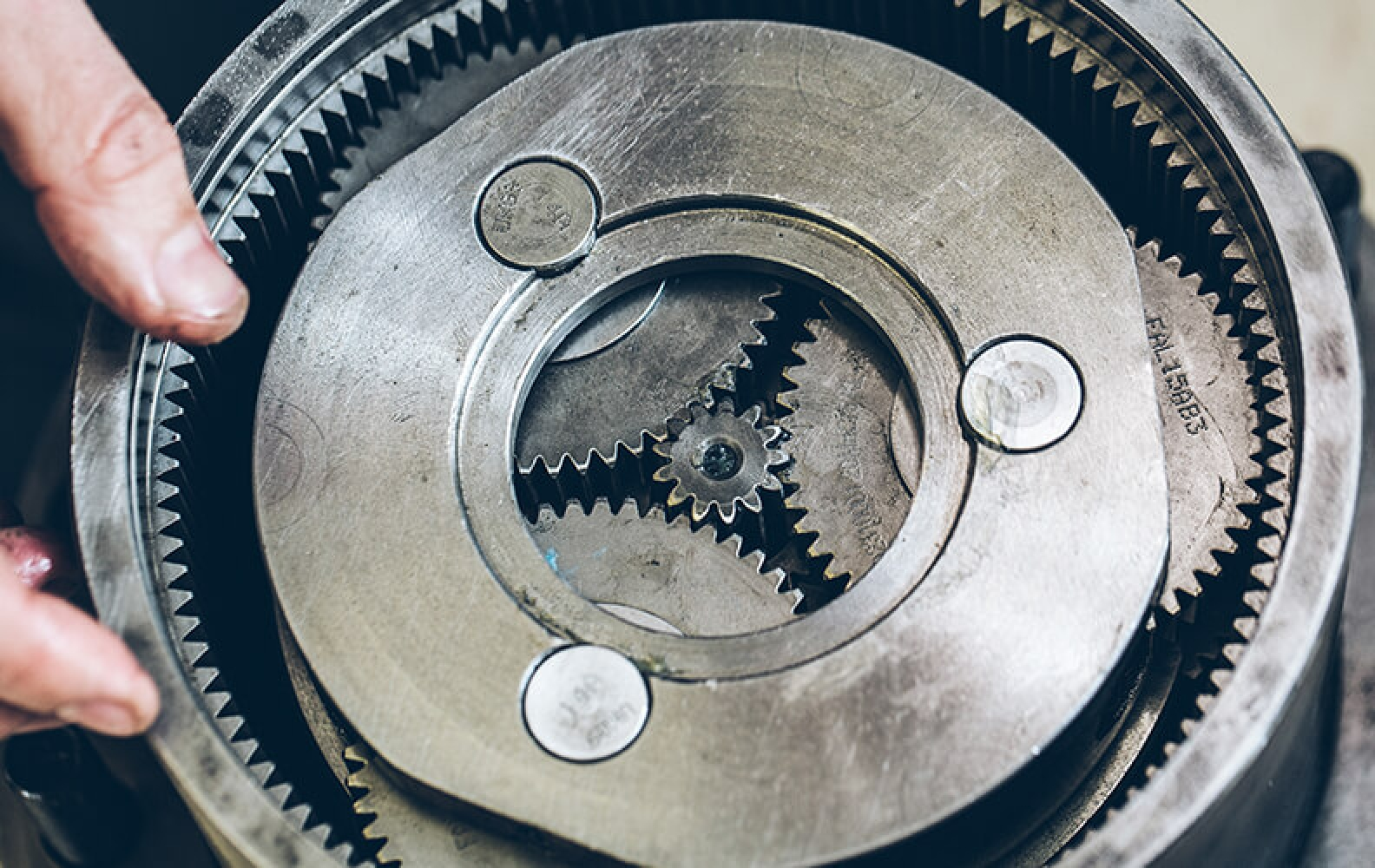
(Extra)
What is this area called? What is the purpose?
Planetary gear system —- A reduction-gear system in which the propeller shaft is attached to a housing containing small planetary gears that rotate between a sun gear and a ring gear. The crankshaft drives either the sun gear or ring gear. The system keeps the propeller shaft aligned with the crankshaft and transmits power with relatively little weight and space.
Basically Meaning:
It is a system that slows down the speed of rotation while increasing power (torque).

Identify These Parts (List 19-23)
Piston skirt — The piston base is extended to form the piston skirt, which helps align the piston in the cylinder.
Ring groove/ Ring Grooves — A groove machined into the outside surface of the piston to hold a piston ring.
Compression rings — Located in the ring grooves immediately below the piston head and prevent combustion gases from escaping around the piston during engine operation.
Oil scraper ring — Also called an oil wiper ring. It regulates the amount of oil that passes between the piston skirt and cylinder wall.
Piston pin / wrist pin — Joins the piston to the connecting rod. It is sometimes called a wrist pin because the motion between the piston and connecting rod is similar to a human wrist.
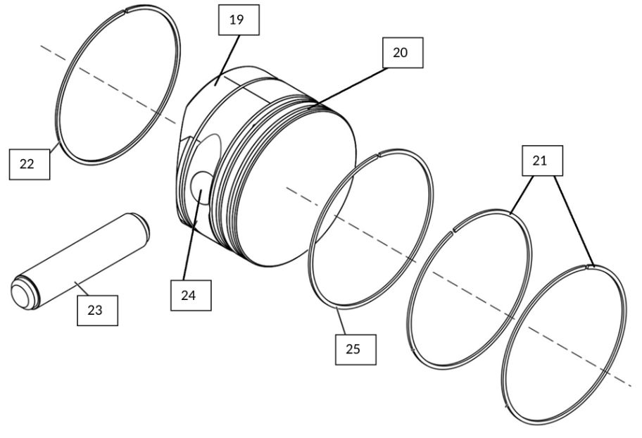
Identify These Parts (List 24-25)
Piston-pin bore — Piston-pin boss as the enlarged area inside the piston through which the piston pin passes.
Oil-control ring — Located below the compression rings and regulates the thickness of the oil film on the cylinder wall. Excess oil is returned to the crankcase through small holes drilled in the piston-ring grooves.

(Extra)
What is this called? What is the purpose?
Piston-pin boss: The thick, heavy hunk of metal built into the sides of the piston to give it extra strength.
(Extra)
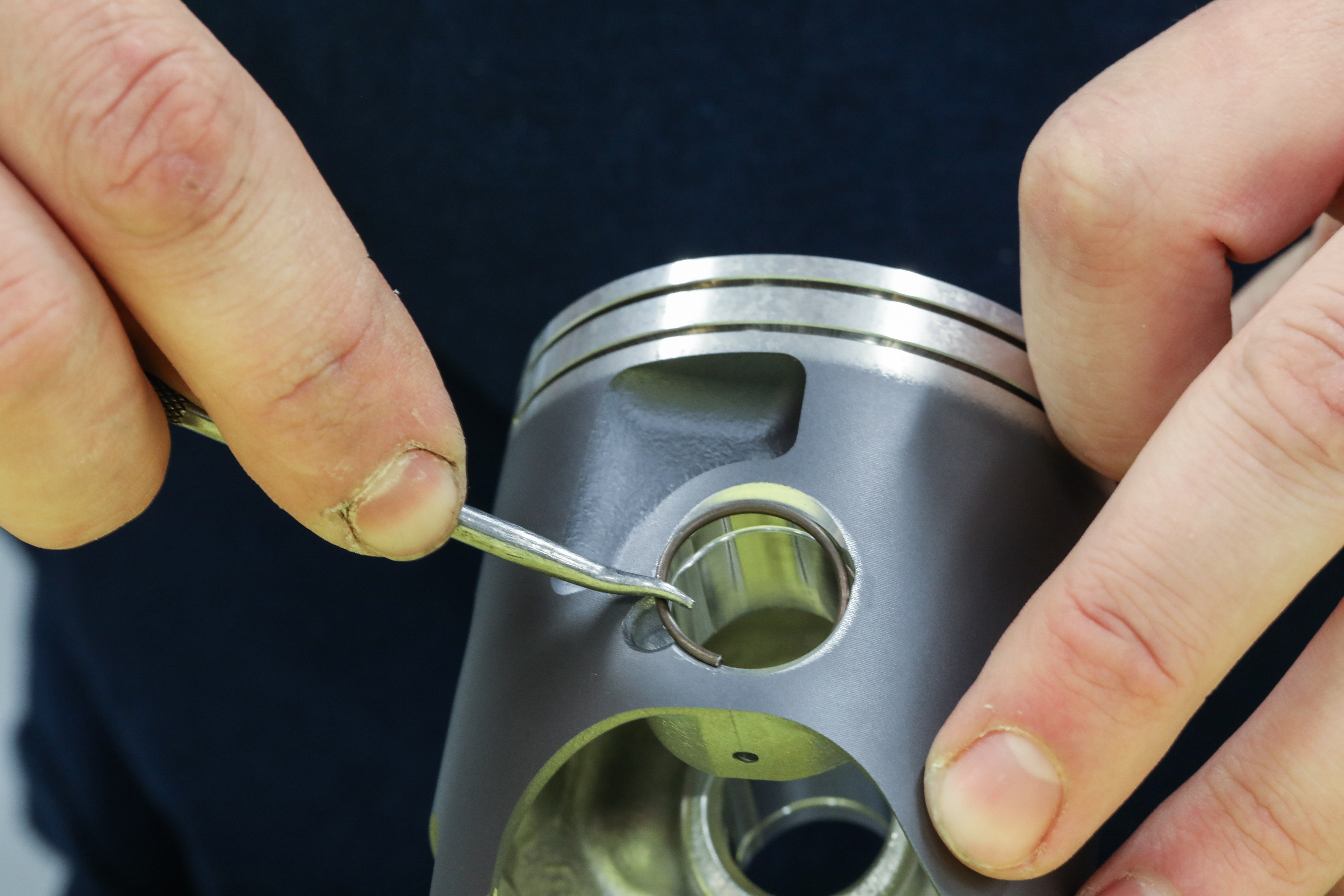
What is being put in the Piston Head?
Spring ring (?) — A device used to hold a full-floating piston pin in place laterally. It fits into grooves at the ends of the piston boss and consists of a single circular spring-steel coil.
(Extra)
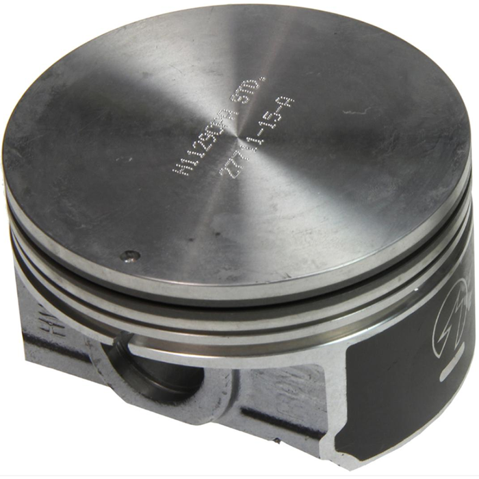
What is this Piston Called? Why is it shaped like that?
Name —- Flat Head
(Most Common)
Why is shaped like this — It is the simplest and cheapest design to make. It creates a smooth, even space for the fuel and air to mix and burn normally.
(Extra)
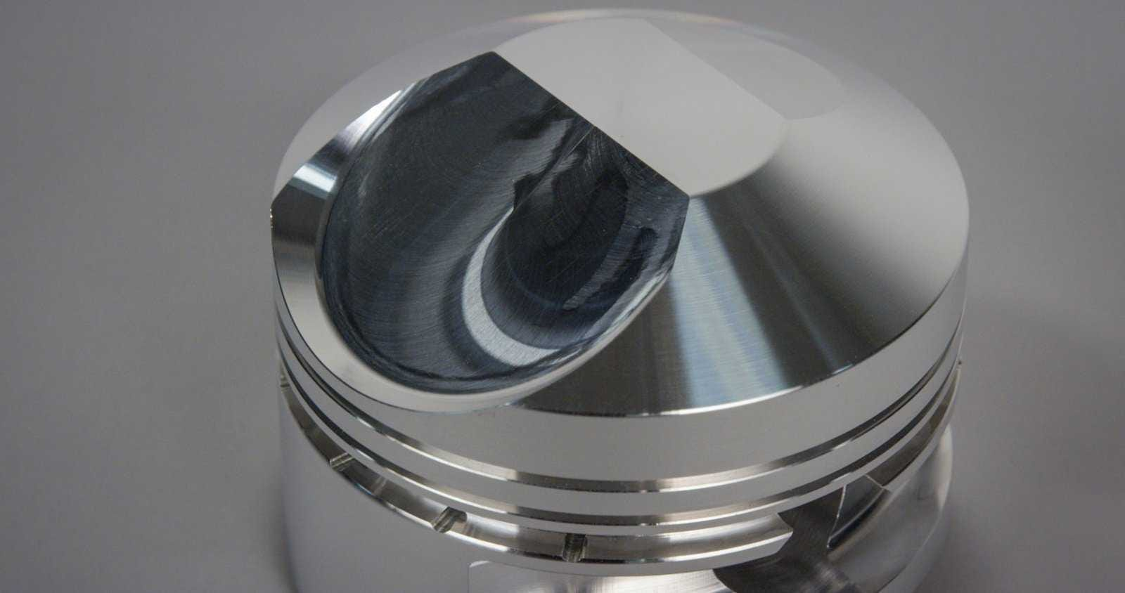
What is this Piston Called? Why is it shaped like that?
Name —-Domed Head
Why is shaped like this —To take away space. By sticking up into the top of the cylinder, the dome leaves very little room. This forces the fuel and air into a super tight space. Squeezing it this hard creates a massive, ultra-powerful explosion,
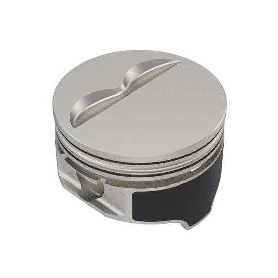
(Extra)
What is this Piston Called? Why is it shaped like that?
Recessed Head
Why is shaped like this — For safety. Inside an engine, metal valves open downward to let air in and out, while the piston rushes upward. The pockets are like tiny escape hatches. They give the valves a safe place to open so the piston doesn't smash into them and break the engine

(Extra)
What is this Piston Called? Why is it shaped like that?
Cupped Head
Why is shaped like this — To add extra space. If you have a turbocharger forcing tons of air into the engine, squeezing it too much will make it explode too early, which hurts the engine. The bowl shape creates extra room so the mixture doesn't get squeezed too tightly, keeping the engine safe and smooth under high pressure.
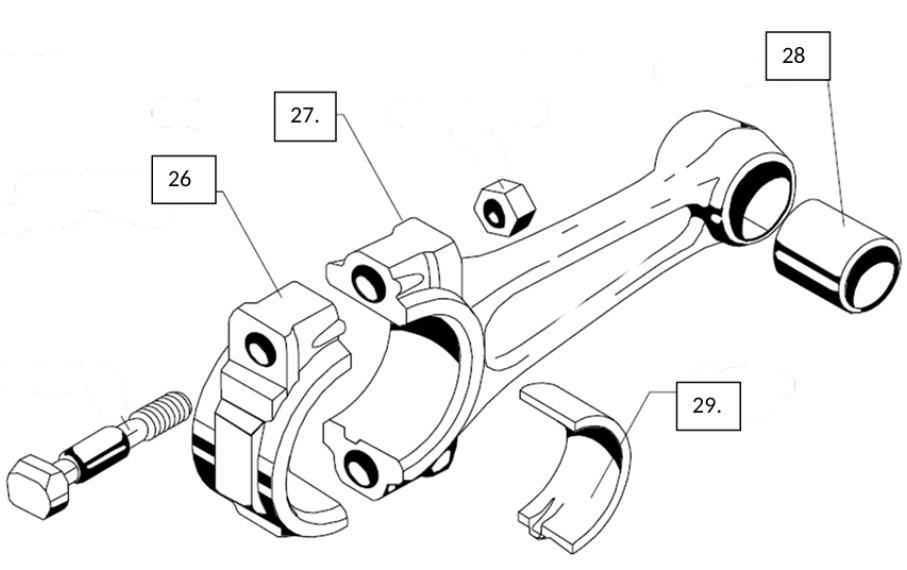
Identify These Parts (List 26-29)
Connecting-rod cap — At the crankpin end of a plain connecting rod, the two-piece bearing is held in place by the cap, which is secured with bolts or studs and nuts.
Connecting rod — The link that transmits the force exerted on the piston to the crankshaft.
Bronze bushing / piston-pin bushing — Pressed into the piston end of the connecting rod and reamed to a precise dimension to fit the piston pin.
Soft-shell bearing / bearing insert — The crankpin end commonly contains a two-piece bearing. The inserts are typically steel lined with a nonferrous bearing material such as Babbitt, lead, bronze, or copper.
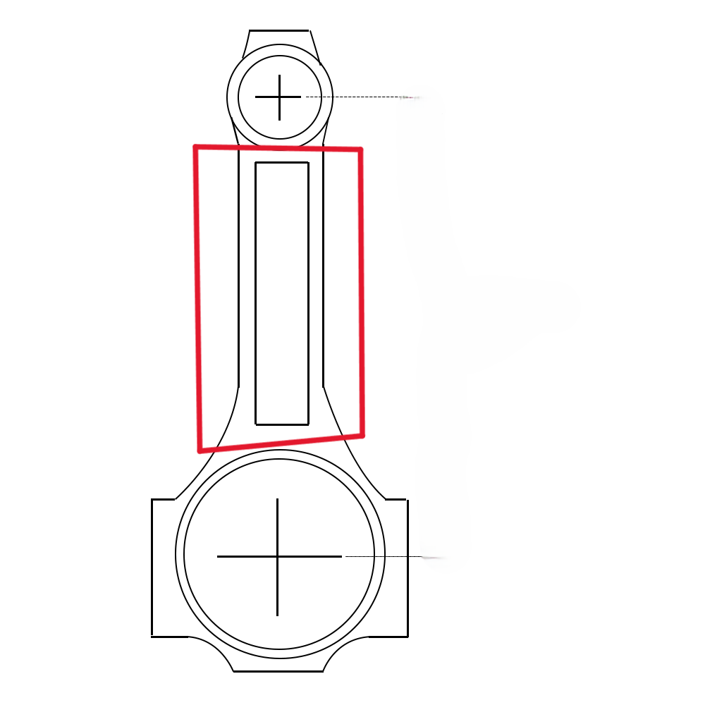
(Extra)
What is this area called? What is the purpose?
Connecting-Rod Shank —- the main middle section of a connecting rod in an engine. It connects the small end (which attaches to the piston) to the large end (which attaches to the crankshaft).
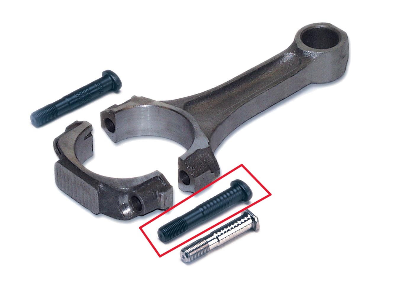
(Extra)
What is this area called? What is the purpose?
Connecting-rod bolts —- Secure the connecting-rod cap and bearing at the crankpin end of the connecting rod.
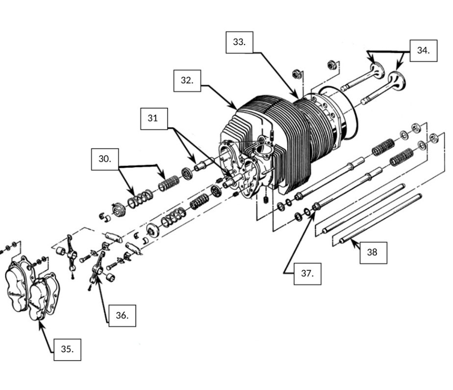
Identify These Parts (List 30-34)
Inner and outer valve springs — Helical-coiled springs that provide the force needed to hold the valve face firmly against the valve seat. Two or more springs of different sizes help prevent valve float or valve surge.
Valve guide — A cylindrical sleeve that supports the valve stem and keeps the valve face aligned with the valve seat.
Cylinder head — Covers the cylinder barrel to form the enclosed combustion chamber. It also contains the intake and exhaust ports, spark plugs, and valve-actuating mechanisms and transfers heat away from the cylinder barrel.
Cylinder barrel — The barrel is the portion of the cylinder containing the cylinder bore. It is machined from a forged blank and includes a skirt, mounting flange, and external cooling fins.
Intake and exhaust valves
Intake valve — Controls the amount of fuel-air mixture entering the cylinder through the intake port.
Exhaust valve — Allows exhaust gases to leave the cylinder through the exhaust port.
Identify These Parts (List 35-38)
Rocker covers and gaskets — No separate definition is given in the provided textbook pages. The book discusses rocker-box covers as part of the rocker-arm installation.
Rocker arm — A pivoting lever in the cylinder head that changes the lifting movement of the pushrod into the downward movement required to open a valve.
Pushrod housing tube / shroud — A thin metal shroud or tube surrounding the pushrod that runs between the cylinder head and crankcase. In many engines, it also provides a return path for oil from the cylinder head.
Pushrod — Transfers the lifting force from the valve lifter to the rocker arm. A typical pushrod is a hollow steel or aluminum-alloy tube with polished ends and oil passages.
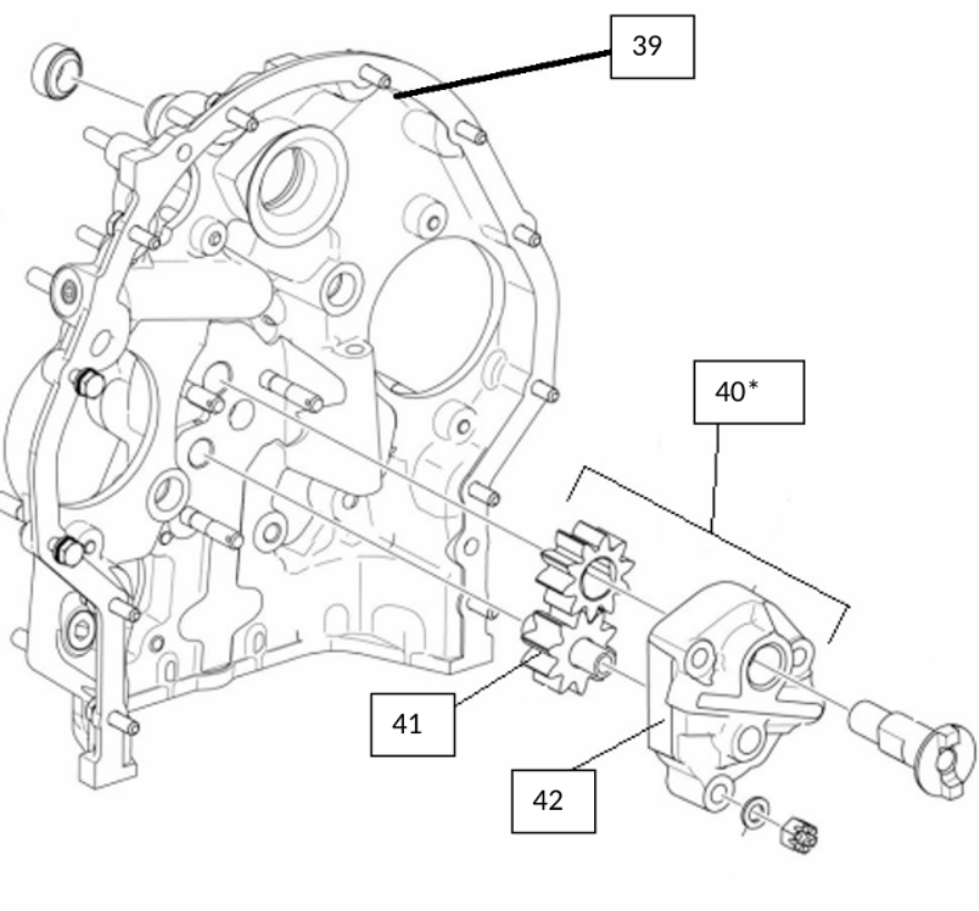
Identify These Parts (List 39-42)
Accessory case / accessory section — Provides mounting points for engine accessories. Its gear train contains gears used to drive engine components and accessories such as magnetos, pumps, starters, and generators.
Oil-pump assembly — No separate definition is given in the provided textbook pages.
Oil-pump drive gear — No separate definition is given in the provided textbook pages.
Oil-pump cover — No separate definition is given in the provided textbook pages.
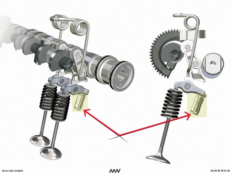
What is this called? What is the purpose?
Hydraulic lifter / tappet
Uses oil pressure to cushion normal impact and remove play in the valve-operating mechanism. A typical hydraulic lifter contains a cam-follower face, lifter body, hydraulic plunger and spring, check valve, and pushrod socket.