EGAD Midterm Review
1/103
There's no tags or description
Looks like no tags are added yet.
Name | Mastery | Learn | Test | Matching | Spaced |
|---|
No study sessions yet.
104 Terms
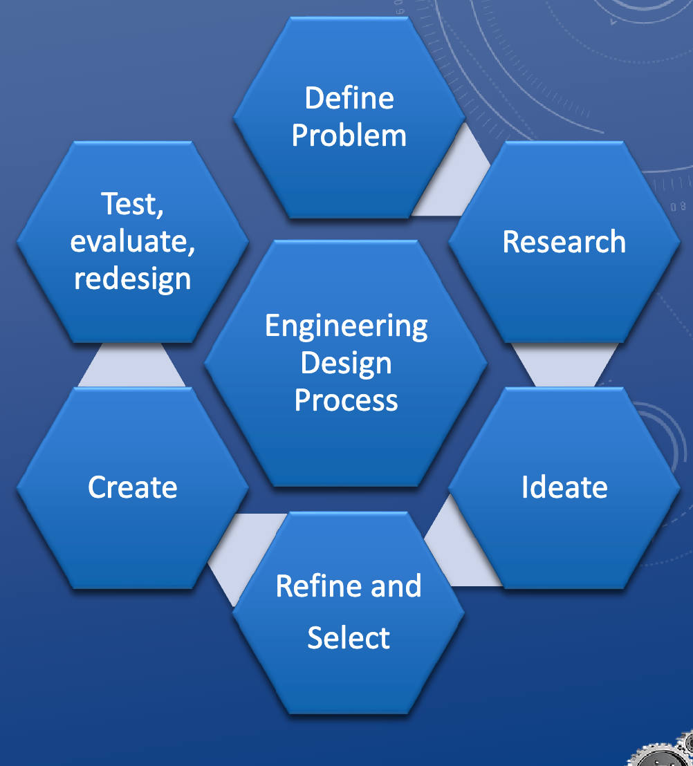
Engineering Design Process
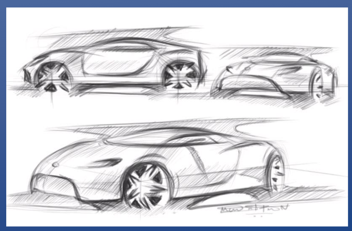
Why is freehand drawing beneficial?
Quick technical drawings, or modifications
• Developing ideas, before & during CAD work
• Presenting conceptual sketches, and debating alternatives
• To aid communication during a technical discussion
Size of engineering lettering
1/8'‘or 3mm
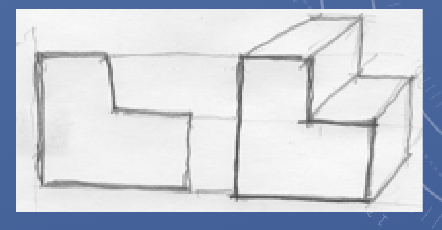
Oblique
One true face
Other faces projected at an angle
Axonometric
Means “to measure along axes”
Three-dimensional pictorial image of an object
Can be difficult to draw depending on angle of view
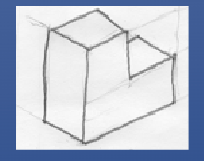
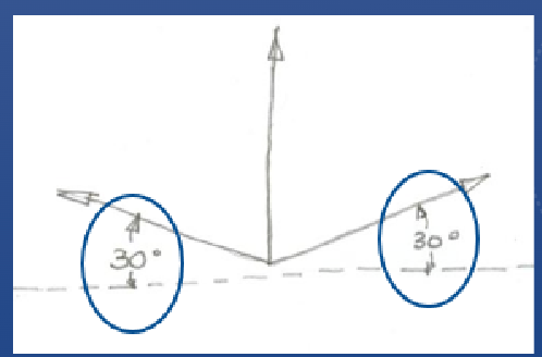
Isometric
Specific axonometric view
Equal proportions for all views
True measurements along three primary axes
Preferred view in technical drawing
Isometric projection
Functions of engineering drawings
Analysis
Production
Maintenance
Assembly
Operation
Types of engineering drawing
Concept Drawings
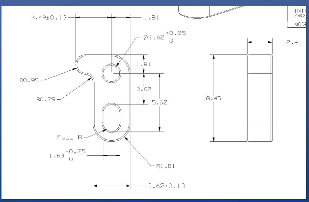
Detail Drawings
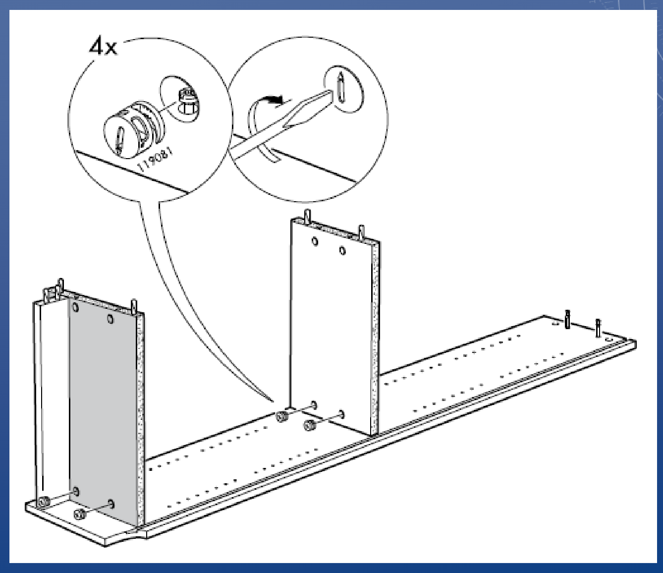
Assembly Drawing
Concept drawing
Detail drawing
Assembly drawing
Border (eng drawings)
Approximately ¼ inch (6 mm) from the outer
perimeter of the drawing sheet; shows a drawing is
complete
Zoning (eng drawings)
A grid system of letters and numbers; allows
reference to various drawing regions (we won’t be focusing on this in EGAD)
Title blocks (eng drawings)
Located in the lower right-hand corner of a drawing and
typically include:
• Company Name
• Main Title and Subtitle
• Scale
• Drawing Date
• Name (possibly also “Checked by” and “Approved by”)
• Drawing Number, Revision Number, Revision Date
Most companies have a pre-formatted title block
Some drawings require an engineer’s stamp
Our title blocks (eng drawings)
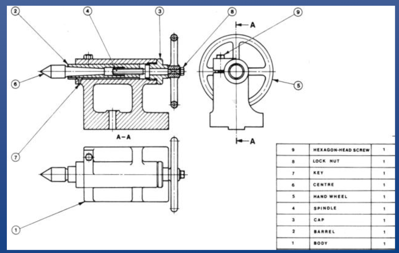
Bill of Materials (BOM) (eng drawings)
a parts list containing the following:
• Name
• Component part numbers
• Material
• Basic dimensions
• Required
Revision column (eng drawings)
• Records changes and approvals
• Numbered, date, brief description of the change, signatures
Notes (eng drawing)
information necessary for the drawing that don’t fit anywhere else
Legend (eng drawings)
explains uncommon drawing symbols
Object line weight
0.6 mm
Hidden line line weight
0.3
Centreline line weight
0.05
Dimension/extension line weight
0.05
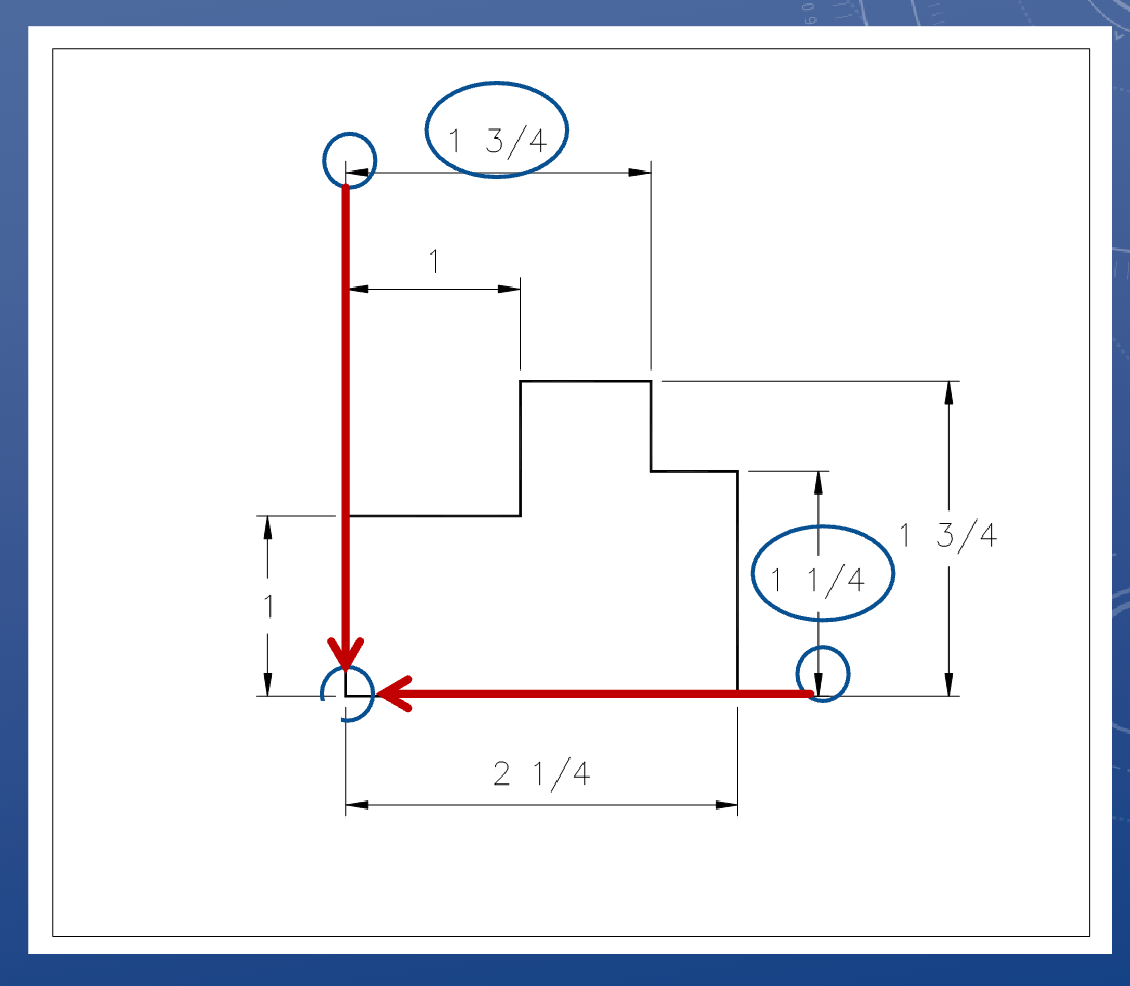
Baseline dimensioning
• In baseline dimensioning, all dimensions in your drawing are measured relative to a specified reference point
• This reference point is called a Datum
*datums can also be object lines
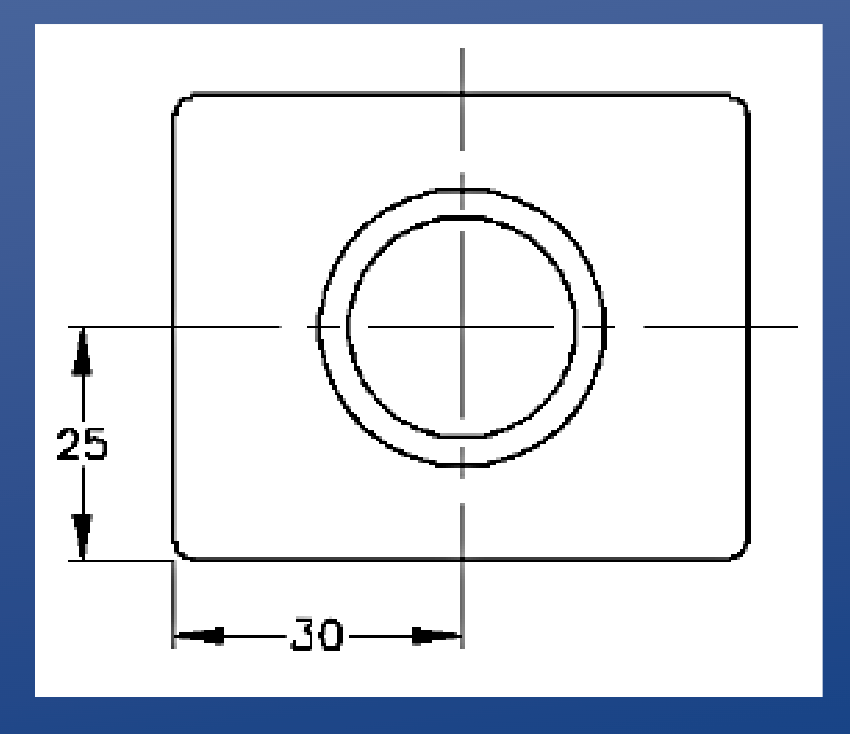
Vertically dimensioning a circle
Always weasure to the centre
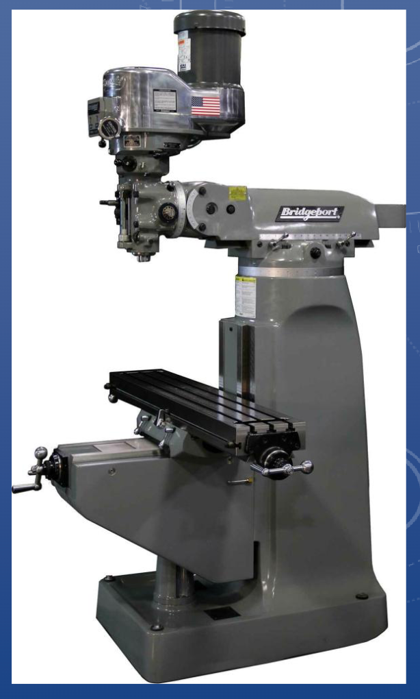
VERTICAL 3-AXIS MILLING MACHINE
• Also known as a:
• Mill
• Milling machine
• Bridgeport mill
• Manual milling machine
• Used for high precision cutting operations
• Cranks are used to move the table in xyz
• Workpiece is fixed to table and moved against rotating tool
Tooling is mounted to the spindle. Measurements can be taken from the crank or digital readout. Machinists establish a datum by zeroing out the digital readout.
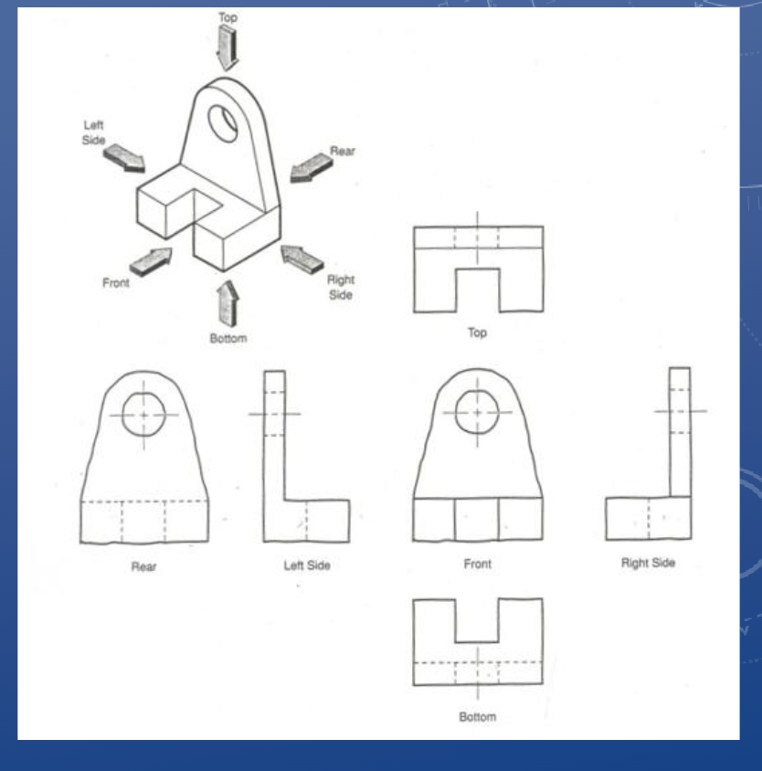
Orthographic view
An object can be viewed from
6 orthogonal (i.e. 90° apart)
directions, also known as the
principal views:
1. Top
2. Front
3. Right Side
4. Left Side
5. Rear
6. Bottom
When creating your orthographic views, they must be placed in the correct orthographic position/orientation
• Everything is projected off the Front view
• i.e. Top view is always above the Front view, Right-side is always to the right of the Front view, etc.
*only include hard edges (no curvature)
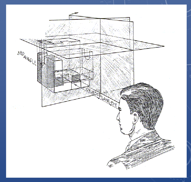
Third angle projection
Views oriented from the perspective of an outside
observer
• The plane of projection
(drawing surface) is between
the object and the observer
• North America typically uses
third angle projection
• Europe and Asia typically use
first angle projection
Picking orthographic views
Maximize clarity by:
• Matching intuitive orientation (T/F/RS)
• Reducing hidden lines
• Showing the most relevant features
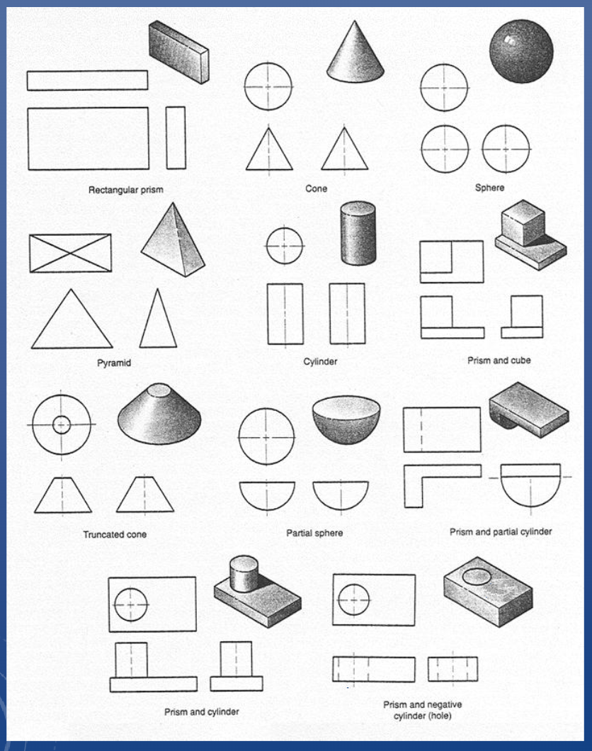
Orthographic views of common shapes
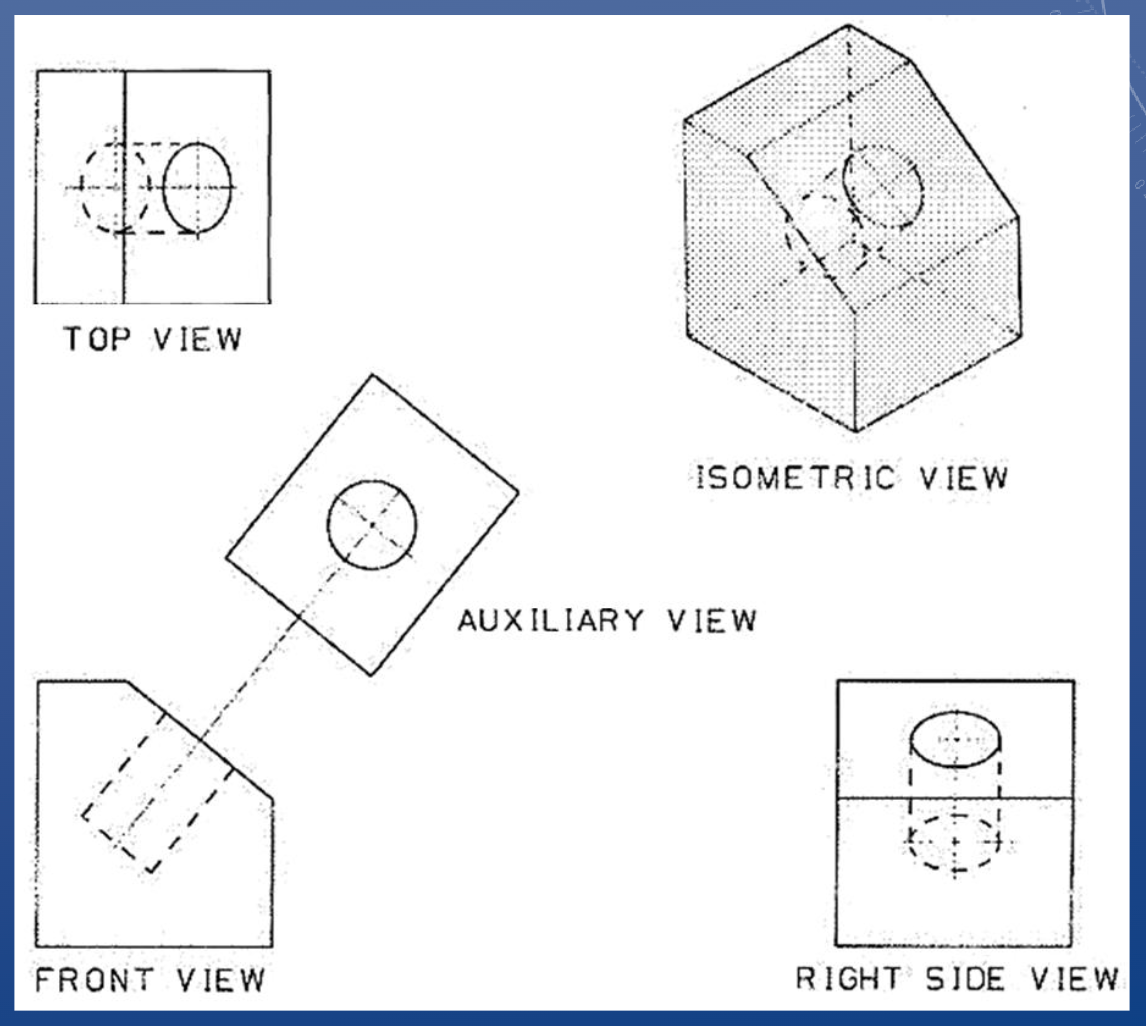
Auxiliary views
Used when the standard views will
not provide a desired detail
• It is an orthogonal projection – at an
angle to the primary views
• You are not expected to be an expert
on auxiliary views, but a general
understanding is required
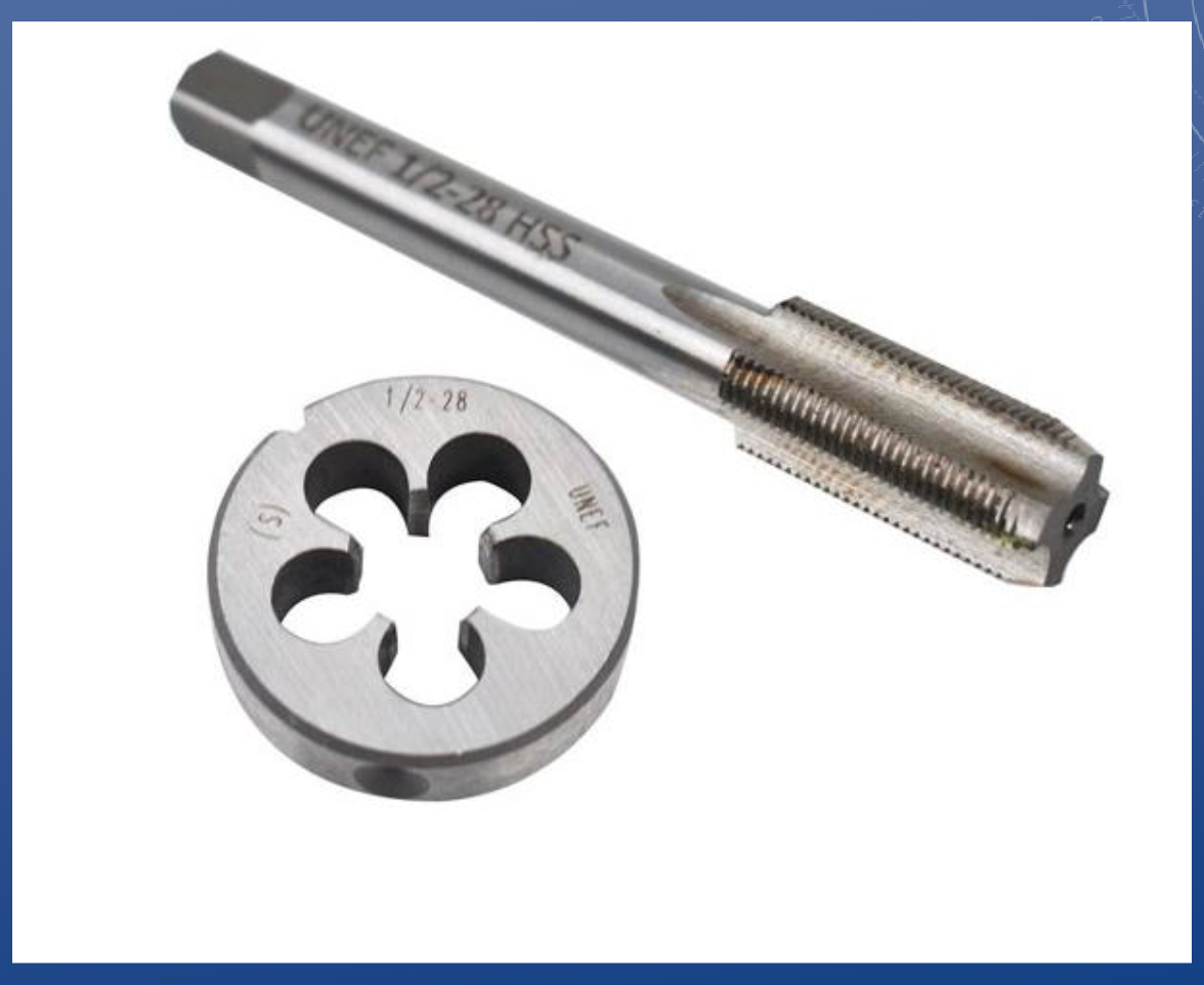
Tap and Die
TAPS
• Used for cutting internal threads into a hole
• Note the tapered tip
• Cannot tap to the bottom of a “blind” hole (i.e. a hole that doesn’t go all the way through)
DIES
• Used for cutting external threads (i.e. threaded rods and bolts)
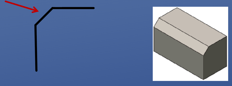
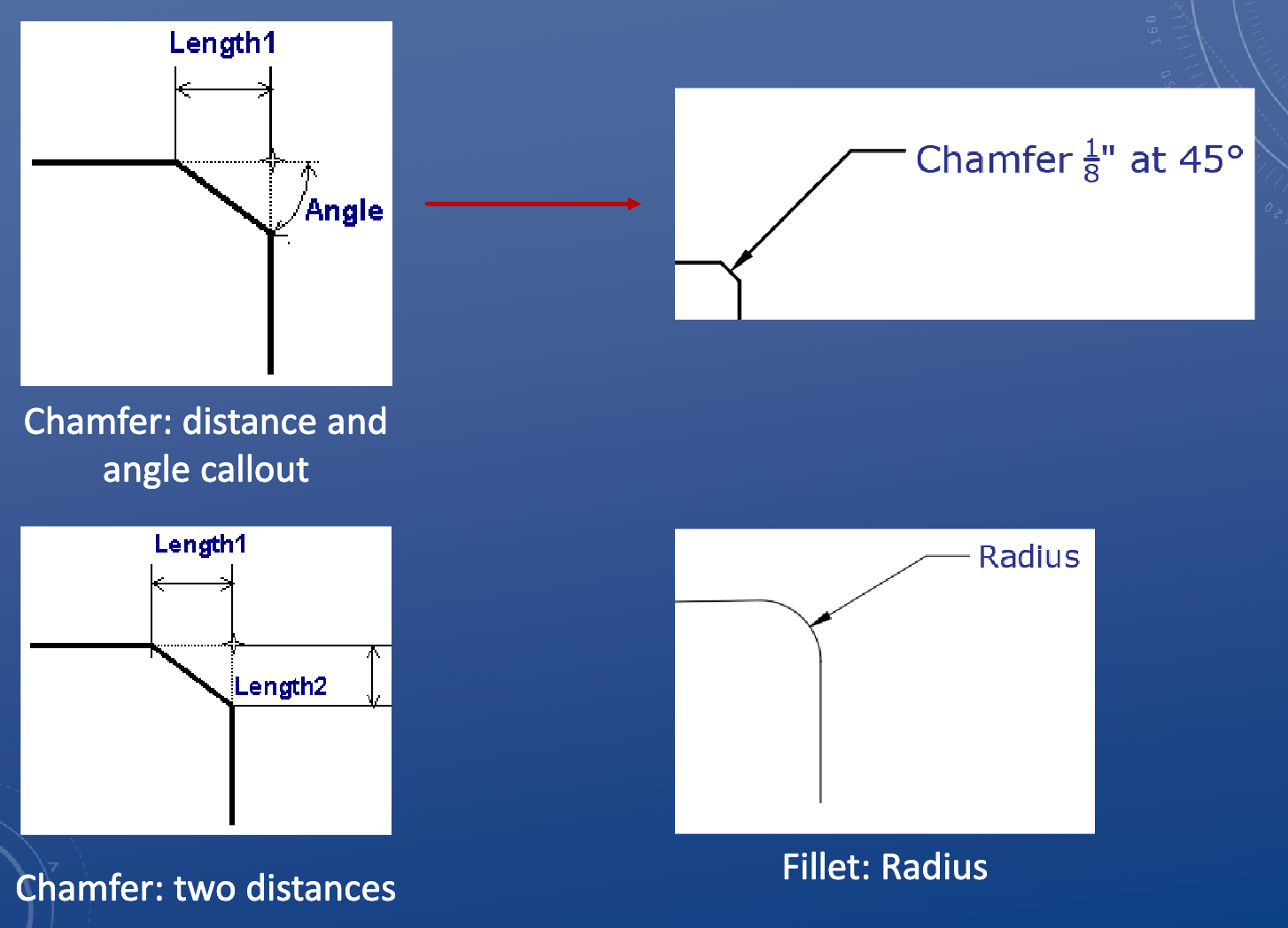
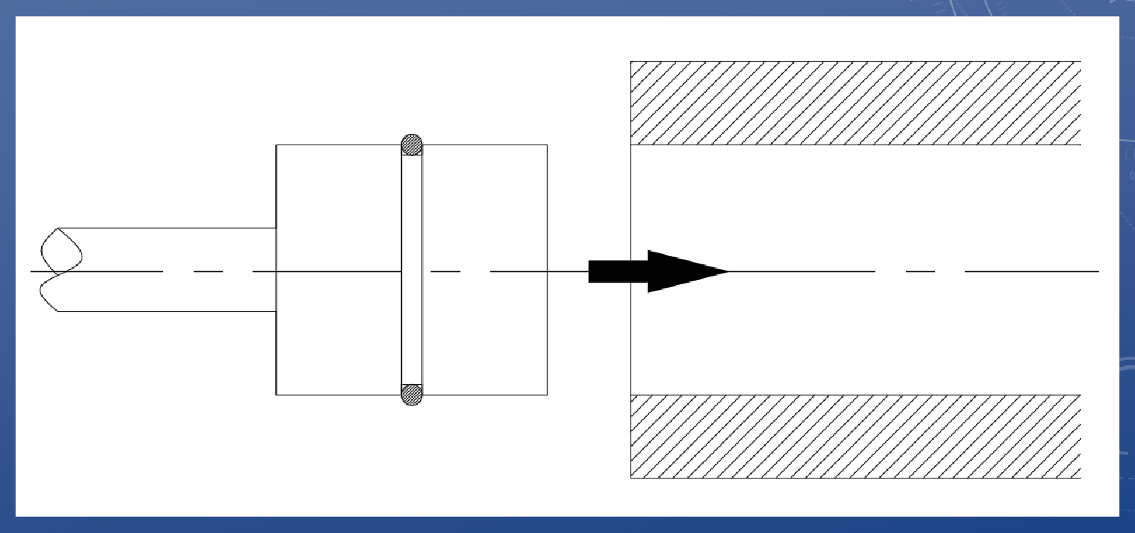
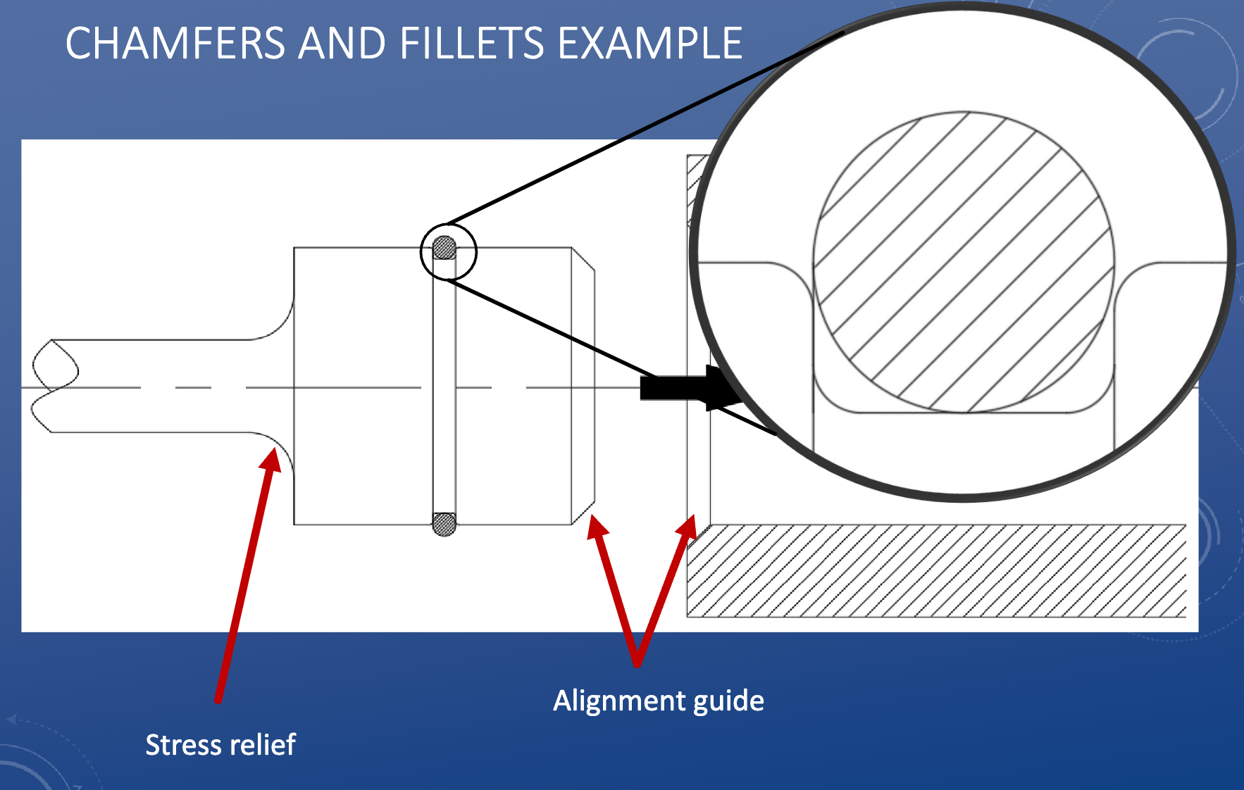
Chamfer
A bevelled edge, consistent angle
• Chamfers are relatively small (<1”)
• Usually on outer edges
• Typically produced by “knocking off” a corner
• Not a mating surface
Functions:
• Appearance
• Safety: removes sharp edges
• Part interactions/fit: easier lead-in
Fillets
A curved edge, consistent radius
• Fillets typically have a small radius (<1”)
• Always tangent to both faces
• Rounds off existing corners
• Allows material to be left after a machining process
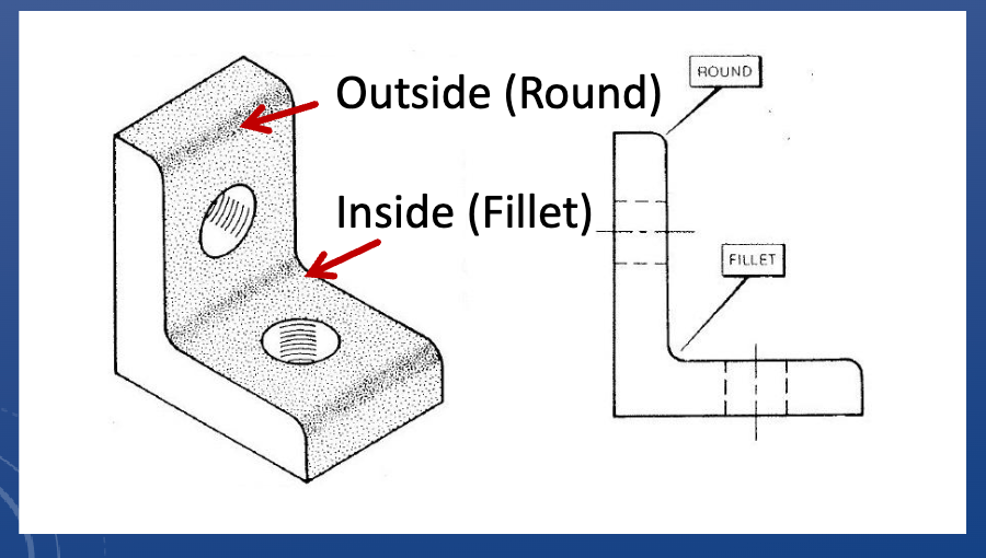
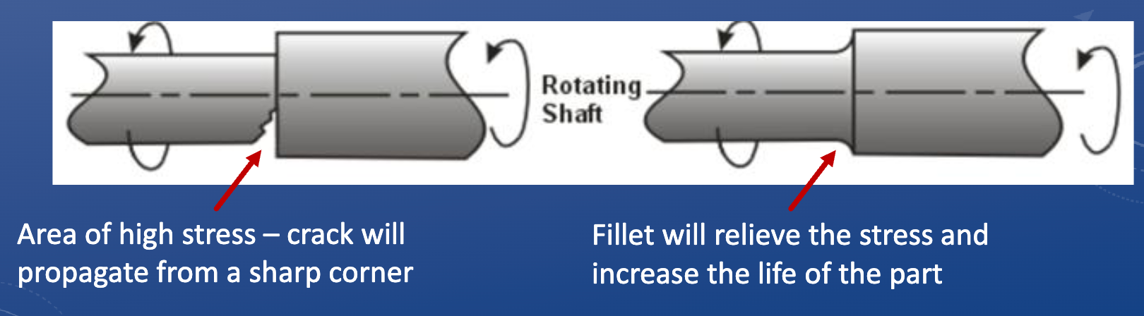
Function of fillets
• Appearance
• Safety: removes sharp edges
• Cost reduction: ease of machining = less time spent
• Strength: reduces stress concentrations
Dimensioning chamfers and fillets
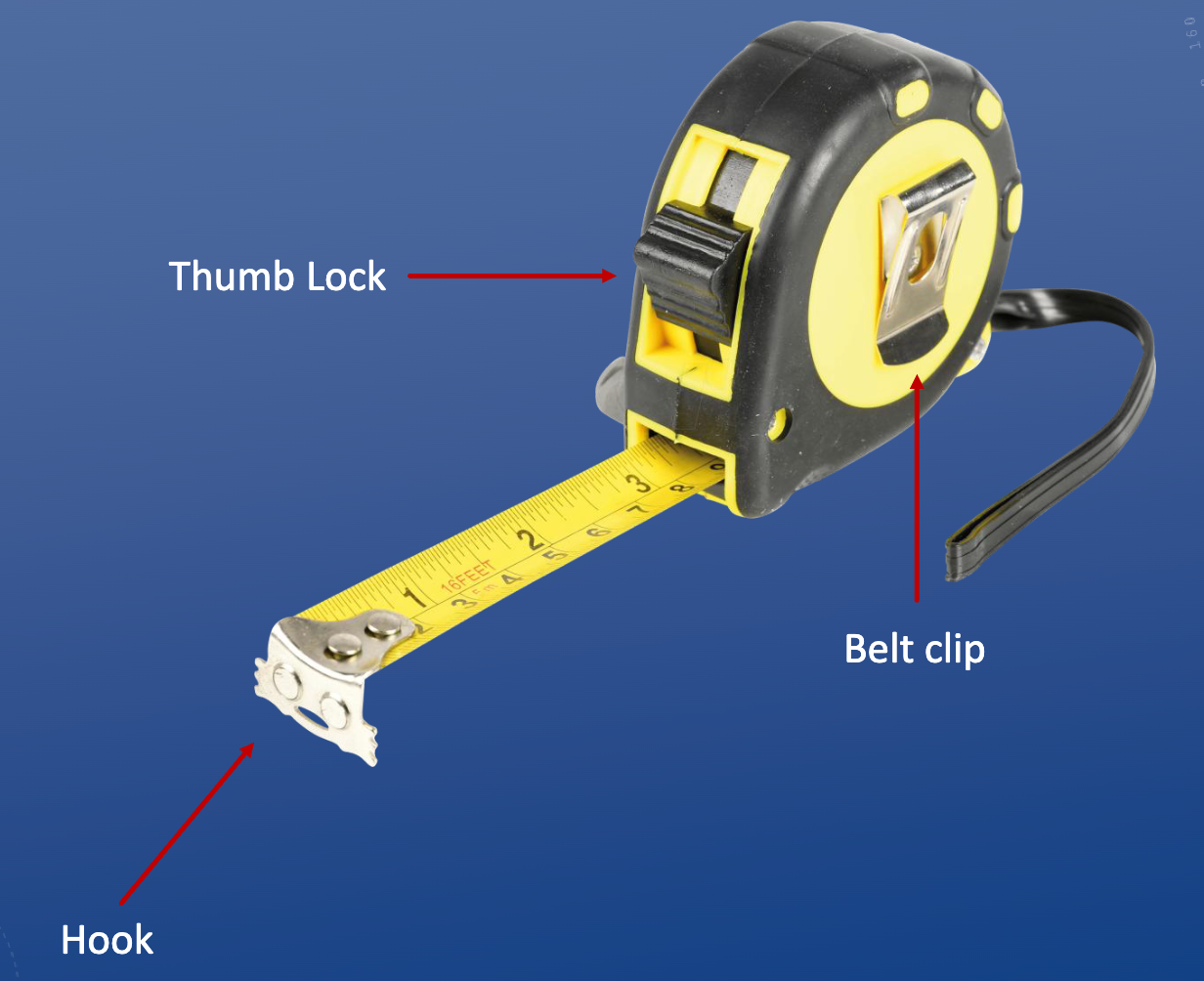
Tape Measure
End wiggles around so you can hook it onto things/push it up against things.
Slot on the end for hooking onto screws.
Max tape measure resolution: 1/16”
*Woodworking has tolerances between 1/64” and 1/8”
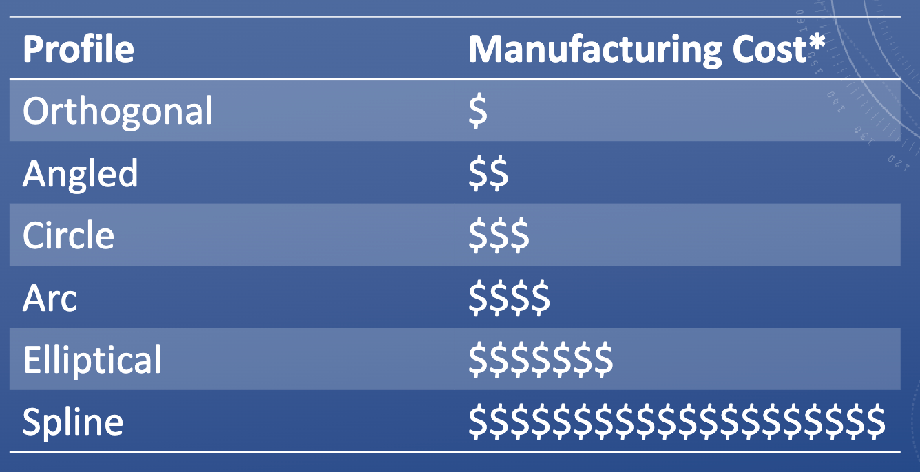
Curves and design considerations
Cutting plane line weight
0.8mm
Hatching line weight
0.15mm
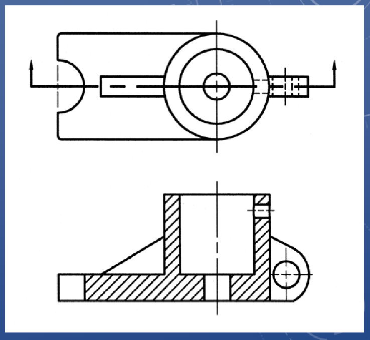
Section views
Why?
1. To reveal internal geometric properties
2. To communicate graphical details clearly
3. To avoid a mess of hidden lines
4. To show material composition
• Whenever possible, section views are aligned in proper orthographic position with the view that contains the section line (and can go in place of an existing view)
• Note: Do not include hidden lines in section views
Uses:
1. Round objects such as wheels and pulleys
2. Parts with webs and fillets
3. Parts that have complex holes in them
4. Enclosed spaces where material has been removed
5. Equipment layouts
6. Assembly views
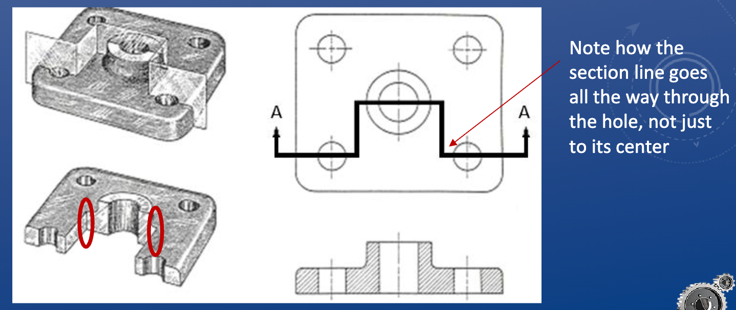
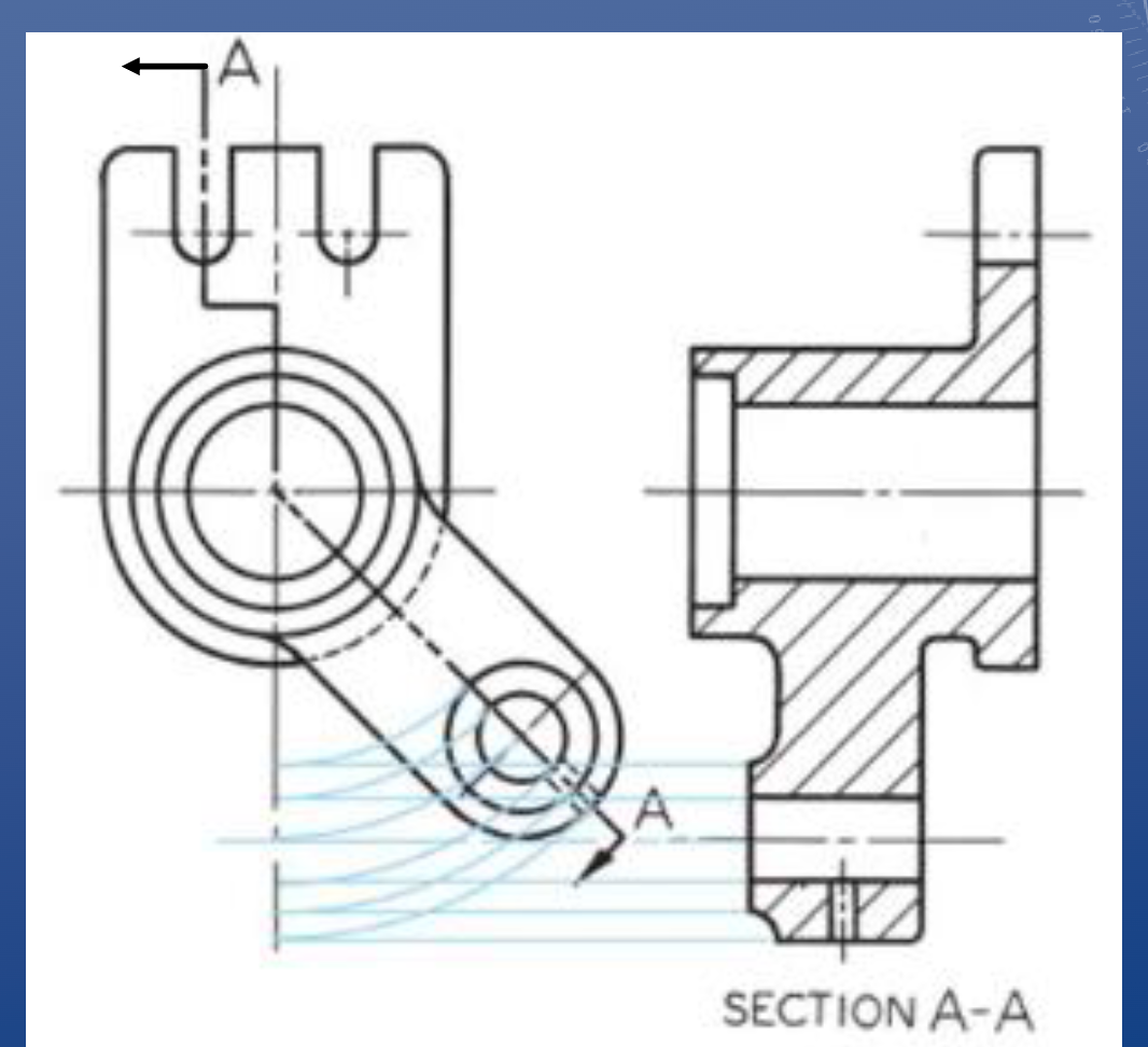
Offset cutting planes
• Two important notes about offset cutting planes:
• Any jogs in your cutting plane must be perpendicular to your view
• Any hard edges created by the cutting place do not appear in the sectional
view, as those hard edges don’t actually exist in the part
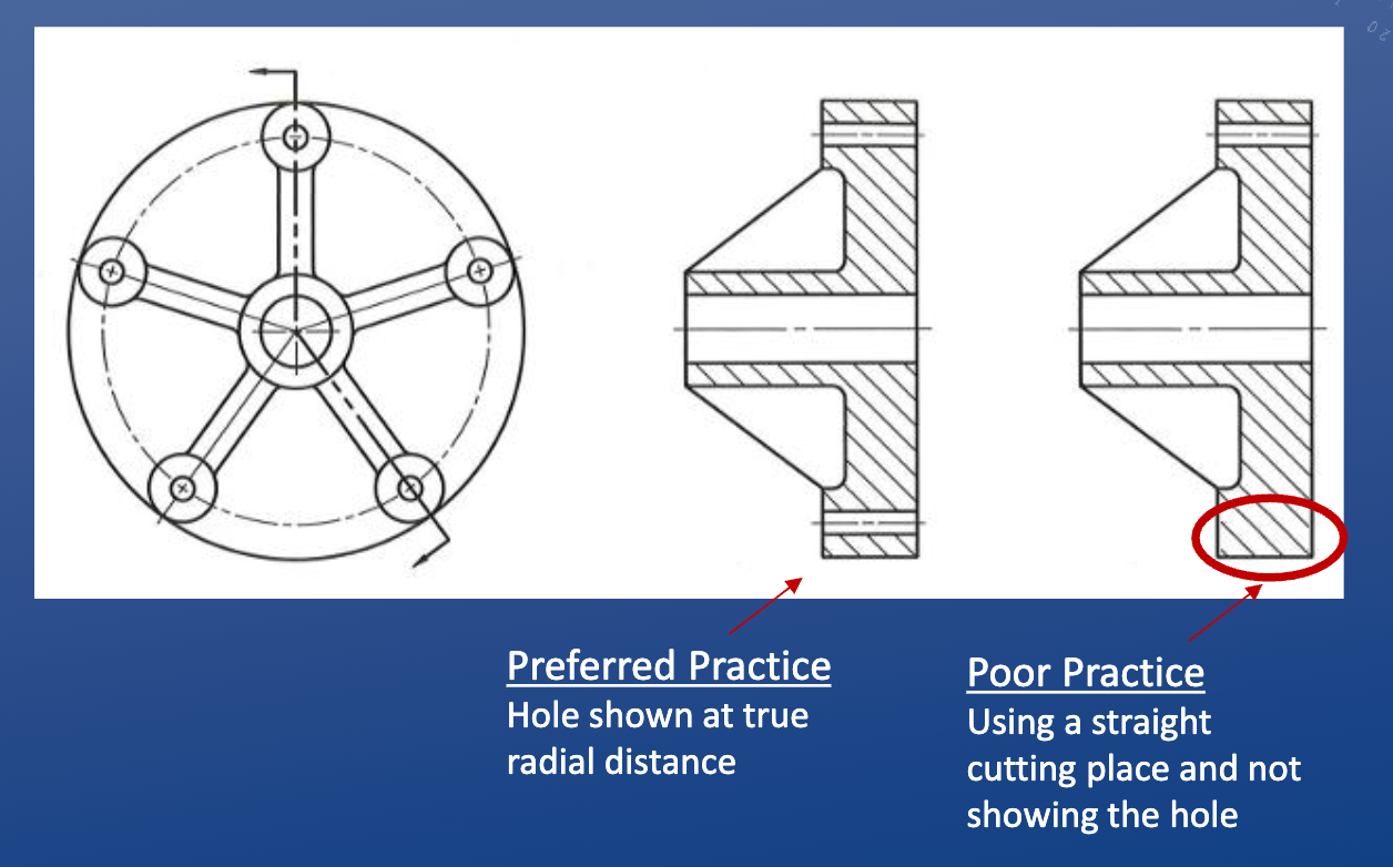
Aligned cutting plane
*If cutting through thin material (i.e. < 1 cm thick), you do not hatch that section even if you’re cutting through it
Combined aligned and offset section
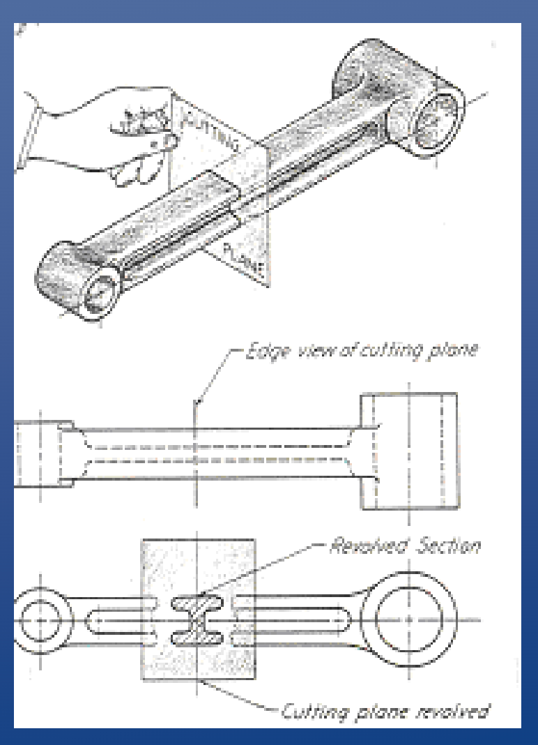
Revolved section
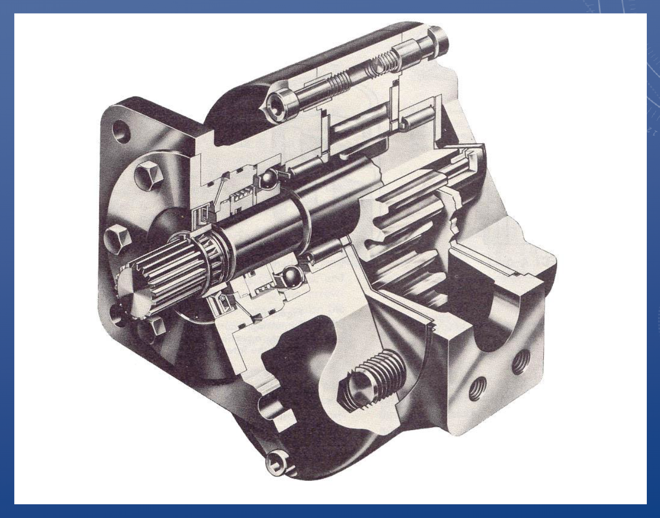
Assembly section view
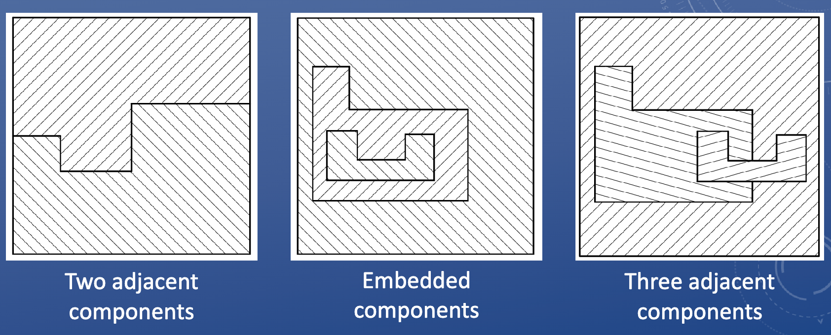
Hatching adjacent components
Dimensioning terminology
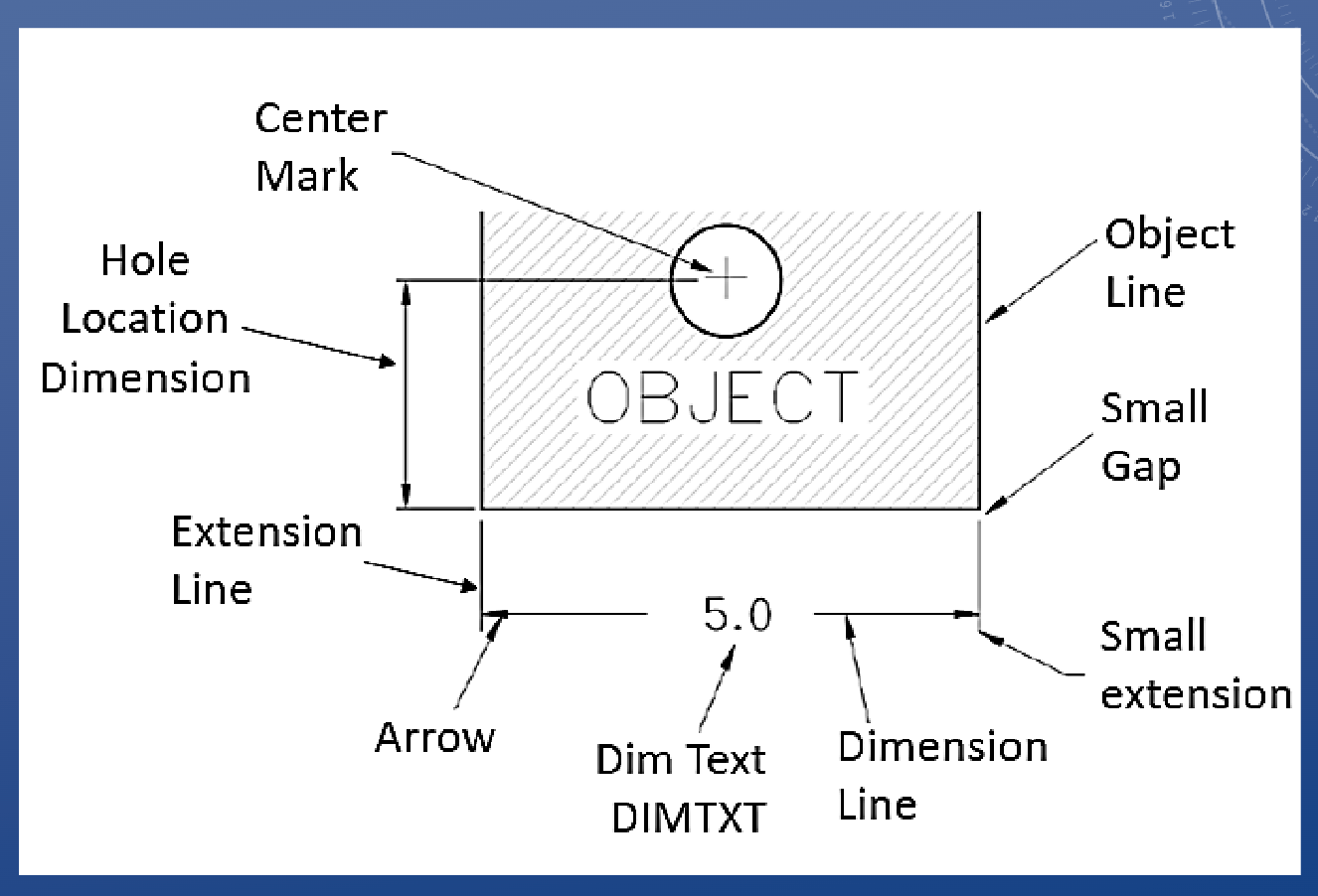
Every dimension should…
a. Be clear so that it can be interpreted in only one way
b. Be kept off the part wherever possible
c. Denoted features in one view only (if possible); e.g. diameter and depth of drilled hole
2. A dimension line should never…
be joined end to end with any line of the drawing
3. Dimension lines should be spaced uniformly;
they should be ~10mm (3/8”) from the object outline and 6mm (1/4”) apart
4. Longer dimensions should be placed
outside all smaller dimensions, so that dimension lines do not cross extension lines
*It is okay to cross extension lines, but dimension lines should never be crossed