MOD 2 - Lines and Tubes
1/62
There's no tags or description
Looks like no tags are added yet.
Name | Mastery | Learn | Test | Matching | Spaced |
|---|
No study sessions yet.
63 Terms
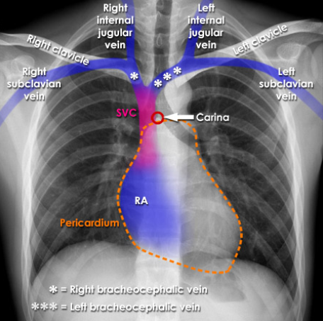
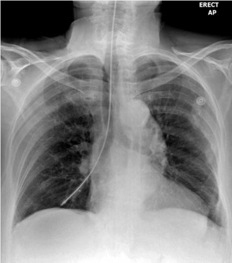
Central Lines (CVC's)
a long flexible catheter that is inserted through the skin and placed with the tip residing within the SVC
Function of Central Lines
reliable, long term infusions of one or more medications simultaneously
to alleviate the need to continually access short-term peripheral IV's in patients (chemotherapy, dialysis, frequent blood testing)
three categories of Central Venous Catheters (CVC)
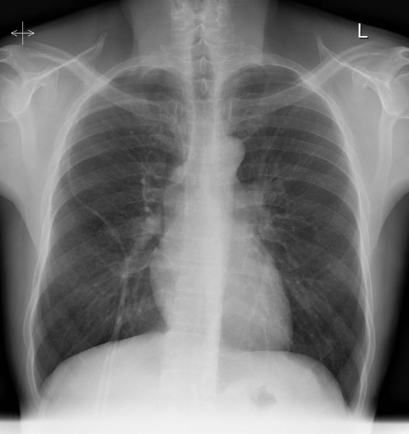
Non-Tunneled Catheters
Tunneled Catheters
Peripherally Inserted Central Catheter (PICC).
Non-Tunneled Catheters (NTC) Patient Condtion
acute
NTC Common Insertion Sites
subclavian or jugular veins, with a preference towards the right side as it takes a direct path to the SVC
Tunneled CVC's Patient Condition
generally well and physically able but require ongoing venous access for outpatient therapies such as chemotherapy, dialysis, or long-term antibiotic treatment
Common Tunneled CVC's
Hickman lines
Broviac lines
Permacath catheters (used for dialysis)
Tunneled CVC's Insertion Process
a portion of the catheter is routed through a subcutaneous tunnel created beneath the chest skin which then enters one of the central veins (jugular or subclavian)
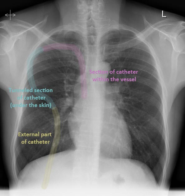
Tunneling Technique Benefit
helps reduce the risk of infection and contamination while also providing added protection against accidental dislodgement or damage
Port-a-Cath Line
Another type of tunneled catheter which does not have any portion of the catheter outside the body, and accessed by a specific needle with extension tubing

PICC Lines Insertion Site
peripherally located on the upper arm, typically the basilic vein
PICC Line Usage
for long or short term use in independent patients who are mostly well, but require regular vascular access for treatment
PICC Line Benefits
offer reduced infection rate compared to other CVC's, reduced risks during insertion and ease of maintenance for the patient
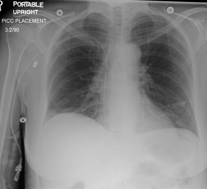
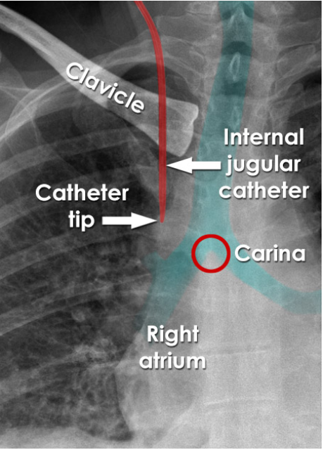
CVC Ideal Tip Location
transversely between the SVC and the right atrium which is at level of the carina T4-5
vertically in the same plane as the SVC
Effects of Catheters that terminate before the SVC
associated with greater risk of infection and thrombosis
CVC Tip Termination for administration of maintenance medications and fluids
within SVC
2cm above carina
3-4 cm right of the vertebral process
Effects of CVC located below the carina
associated with risk of cardiac tamponade
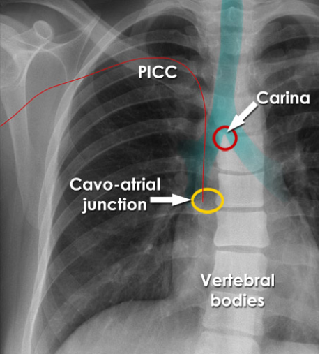
CVC Tip Termination for long term use and infusion of irritating medications (chemo)
terminates within cavo-atrial junction (~2VB down carina)
Atrial Placement
what
risks
not intended however, they may advance unintentionally with changes in patient position, or migration, over time
cardiac tamponade, tissue erosion and perforation
Most frequent malpositioned CVC insertion site
jugular vein
Catheter placed in azygos vein
PICC line placed in Internal mammary vein
Left jugular coiling of CVC
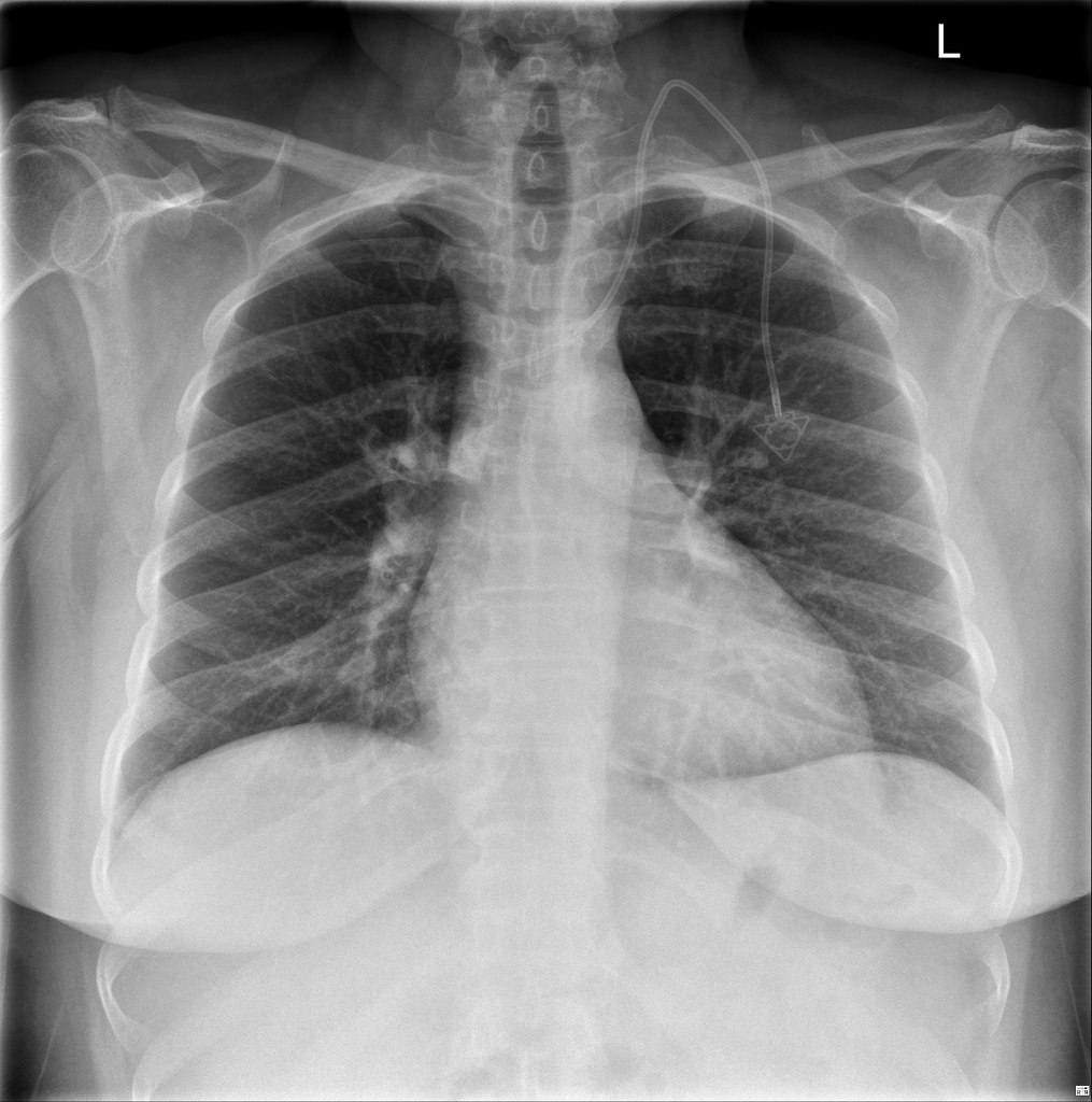
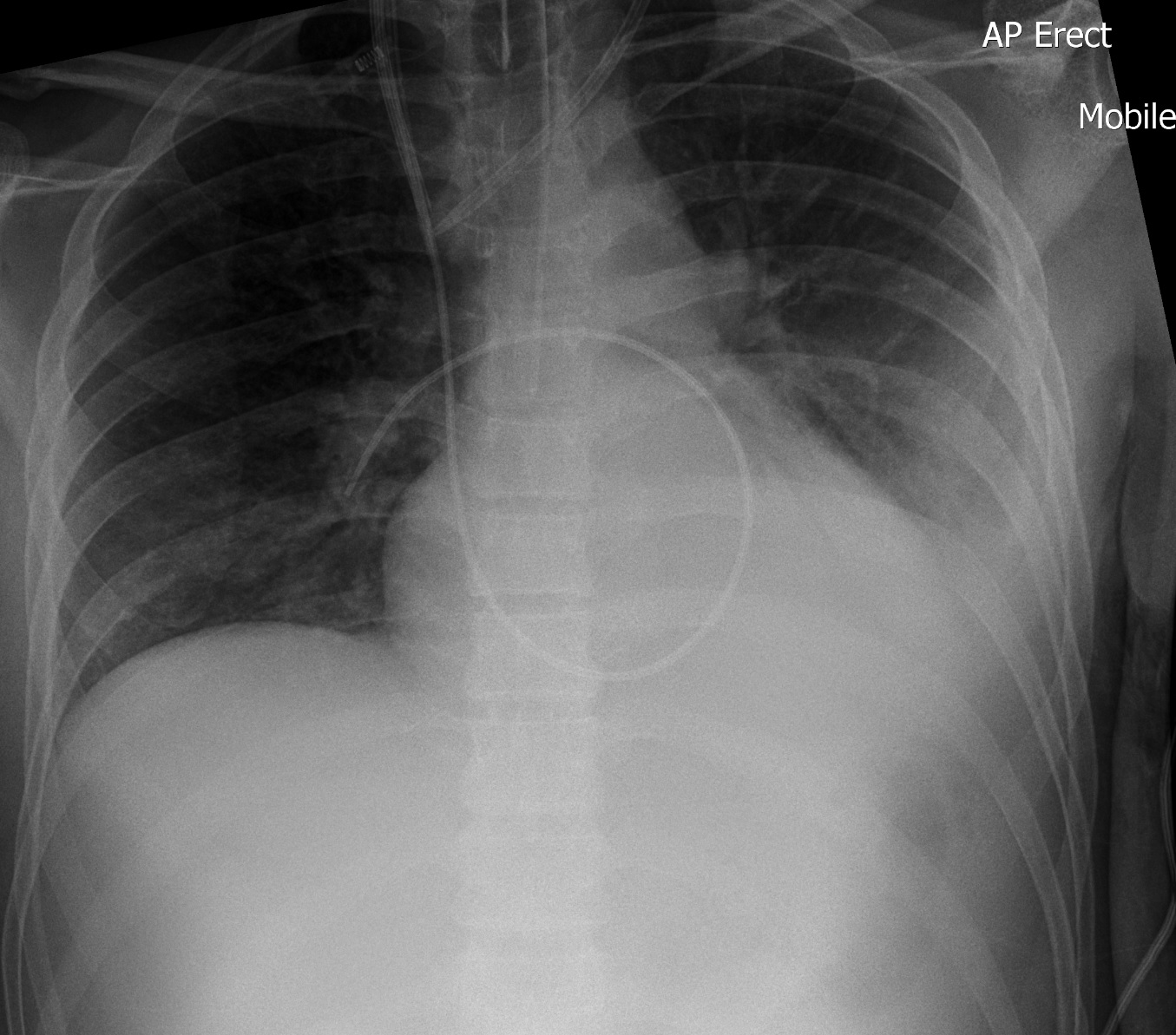
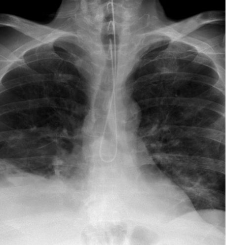
Pulmonary Artery Flow Catheters (PAC's)
what
aka
catheters that measure cardiac output and blood pressures within the heart, typically placed within the heart
also known as Swan- Ganz Catheters
PACS Patient Conditions
often following open heart or chest surgery and pulmonary hypertension
PACS Features
aid in the diagnosis of right or left heart failure
evaluate stress on heart function
monitor oxygen saturation levels between the right and left side of the heart
temperature monitoring
diastolic pressure of the left heart
delivering fluids and medications
PACS Insertion Process and Radiographic Appearance
via the subclavian, jugular or femoral vein and advanced into RA, then with a balloon tip, the catheter is then floated into the right or left pulmonary artery, radiographically the catheter makes a large U-turn within the heart
NG/OG Tube Patient Conditions
declining patient consciousness
to reduce the risk of aspiration
stroke with asphasia
cognitive decline resulting in poor nutritional consumption
oral/esophageal tumor causing obstruction
gastric decompression
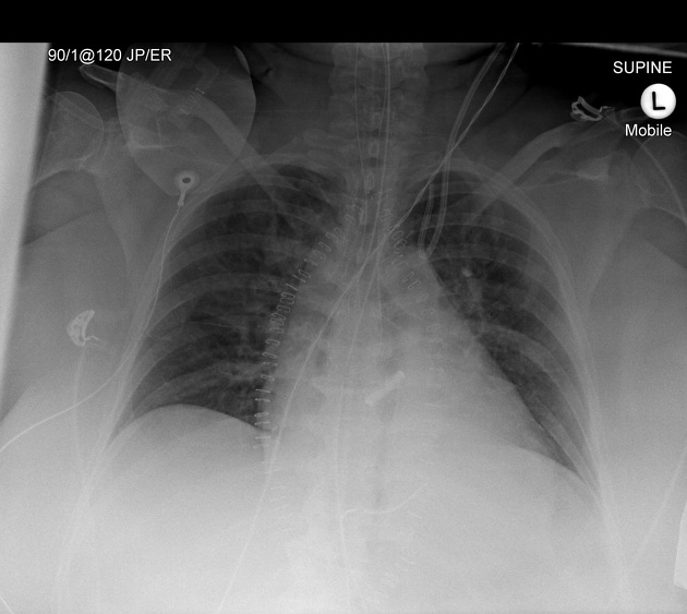
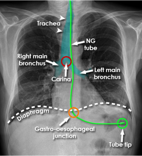
NG/OG Tube Ideal Placement
weighted tip at least 10cm past the gastro-esophageal junction = 10 cm below the diaphragm and overlying the gastric bubble
NG/OG Tube Complications
mild local tissue trauma from the insertion
perforation of the esophagus or mediastinum
pneumothorax
aspiration
hemorrhage and death
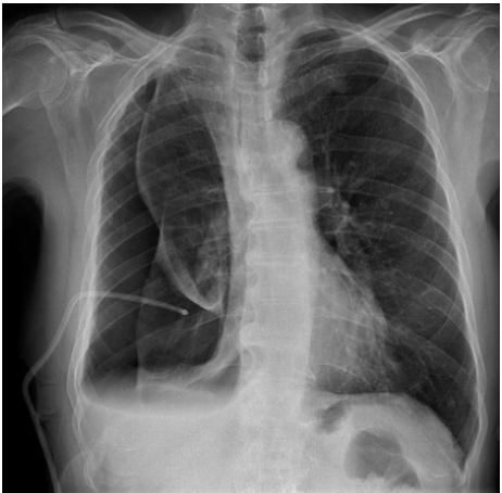
Most commonly mispositioned NG/OG tubes
entering the lung right bronchus
making a u-turn within the esophagus directing the tip back toward the larynx
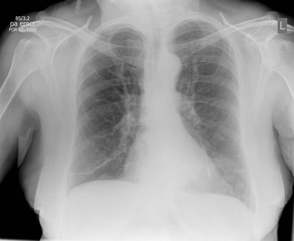
Ideal Radiographic Image of NG/OG Tube
tube should be seen parallel to the spine and slightly to the left
enters the stomach at the level of the diaphragm, where the tube will curve according to the shape of the stomach
weighted tip oriented downward or slightly angled right or left
NG visualized within the right bronchial tree.
NG looped within the esophagus
Insufficient NG insertion
NG in LLL
NG visualized in costophrenic recess
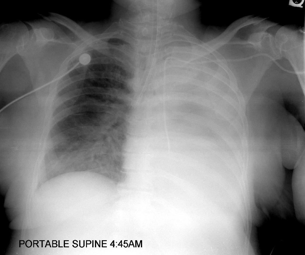
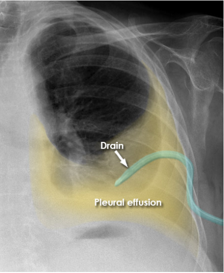
Chest Tubes
inserted using sterile technique, into the pleural space most often at the bedside by care providers to either remove fluid or air
Chest Tube Patient Conditions
may be from critically acute departments such as ICU, CCU or Trauma
non acute patients with chronic lung pathologies or illnesses that cause build up of fluid within the chest
Chest Tube “safe zone“ insertion site
fifth intercostal space, slightly anterior to the mid-axillary line
Main Purpose of Chest Tubes
drainage; either air or fluid from within the pleural space
Common 2 types of Chest Tubes
large bore
small bore
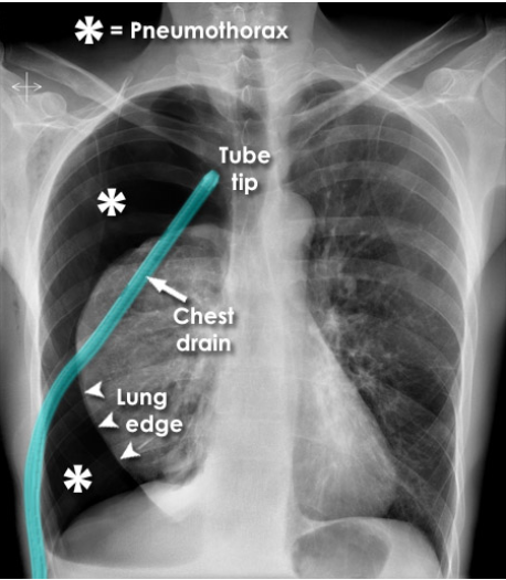
Large Bore Chest Tubes
for pneumothorax
directed to the superior, anterior portions of the pleural cavity, ideally in the apices - since air rises
Small Bore Chest tubes
for fluid drainage
directed inferiorly and posteriorly towards dependent fluid collection spaces - since fluid "sinks"
Complications of chest tube insertion
pneumothorax
surgical emphysema
tension pneumothorax
hemorrhage
Pneumothorax induced during insertion of pleural drainage catheter
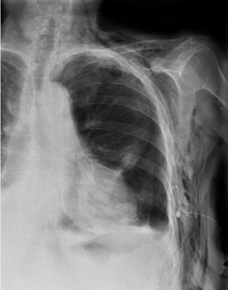
Subcutaneous emphysema (air within the soft tissue) due to pneumothorax and incomplete insertion of chest tube for pleural effusion drain
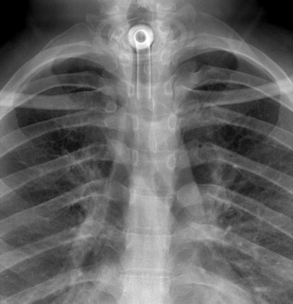
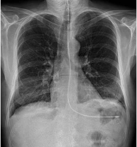
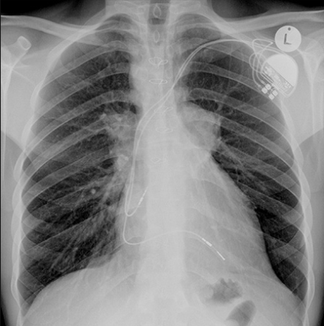
Pacemaker (PM)
an electromechanical device that regulates the heart rate by providing low levels of electrical stimulation to the heart muscle
Primary Purpose of a Pacemaker (PM)
to maintain an adequate heart rate, either because the heart’s natural pacemaker is not fast enough, or there is a block in the heart’s electrical conduction system
Temporary PMs Usage
to treat short-term heart problems, such as a slow heartbeat that’s caused by a heart attack, heart surgery, or an overdose of medicine
Permanent PMs Usage
to control long-term heart rhythm problems
Types of Pacemakers
Internal = implanted inside the patient's chest
External = generally temporary and the bulk of the instrument remains outside the patient's chest in a pocket created under the skin
Pacemaker Insertion
performed under fluoroscopic guidance within the diagnostics department (cardiac catheterization lab or imaging department)
in the operating room, ICU, or CCU with a portable C-arm (but rare)
Patient should not _ within 24hr post pacemaker insertion
patients are not allowed to abduct or elevate their left arm to prevent dislodging of the catheter and pacemaker
Respiratory tubes
allow assistance to a patient if they require aid for air to pass into the lungs
bypass of an area of blockage
protect the airway from aspiration of secretions
to control respiration
two types of respiratory tubes
tracheostomy tube
oral/nasal tracheal tube (Endotracheal (ET))
Endotracheal Tube Insertion Site
introduced into the trachea through the oral cavity (OTT) or nasal passage
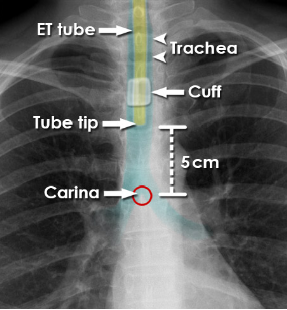
Endotracheal (ET) Tube Tip Optimal Locations
ET tube should be located in the trachea 5-7cm superior to the carina
as neck position affects the location of the distal tip, a radiograph performed with the neck in neutral position
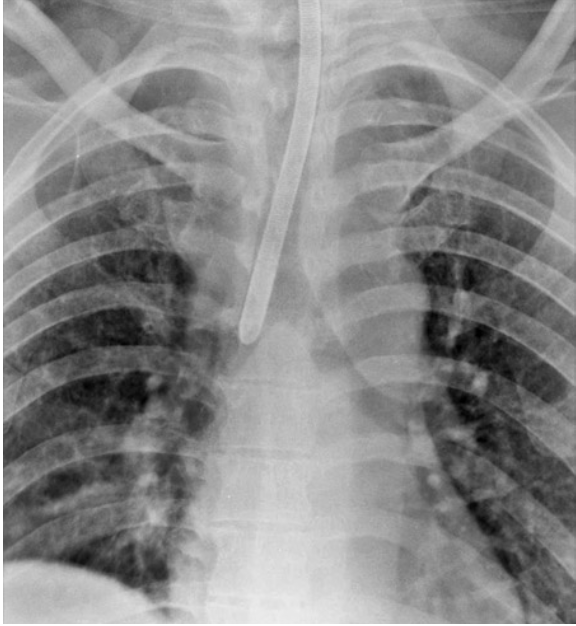
Complications of ET Tubes - ET Tube Inserted Too Far
lung collapse of the contralateral side
Complications of ET Tubes - Esophageal Insertion
ET tubes inserted into the esophagus will result in ventilation of the abdomen and can be fatal
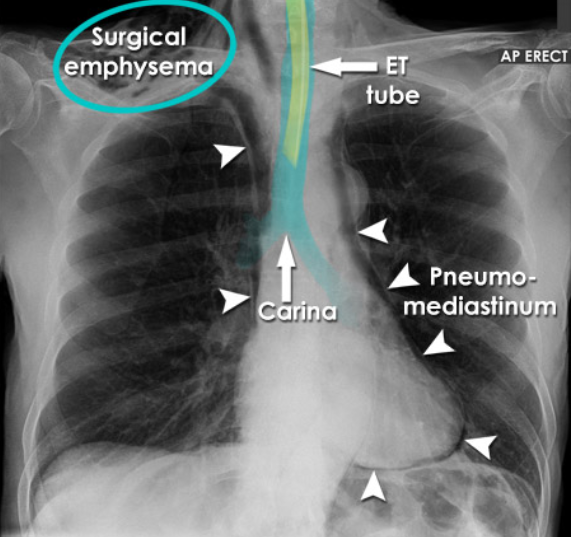
Complications of ET Tubes - Pneumomediastinum and Surgical Emphysema
introduction of air in surrounding areas
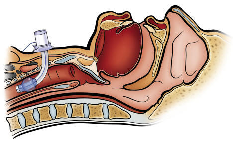
Tracheostomy Tubes
surgical opening in the anterior neck into the trachea to permit long term mechanical ventilation
ETT ventilation is not recommended beyond 14-21 days, due to complications, thus it gets replaced by a TT
Optimal Location for Tracheostomy Tubes
distal tip is positioned at midpoint between the upper end of the tube and the carina, typically 6cm above the carina