BRAE 237 Final
1/22
There's no tags or description
Looks like no tags are added yet.
Name | Mastery | Learn | Test | Matching | Spaced | Call with Kai | Chat |
|---|
No analytics yet
Send a link to your students to track their progress
23 Terms
Errors: Blunders
Due to mistakes, faulty measurements, or wrong methods
Does not follow statistical rules
Must be avoided with care and control routines
Detected by redundancy (multiple observations)
AKA “Gross Errors” or “Outliers”
Example: recording 50° 32’ 50.9’ instead of 50° 32’ 5.9”
Errors: Random
Unpredictable, non-systematic deviations
Caused by instruments, environment or human factors
Smaller errors occur more often than larger ones
Positive and negative errors occur equally
Average tends toward zero with many observations
Studied with: probability and statistics
Errors: Systematic
Follows physical or mathematical rules
Affects results in a consistent way
Causes: instrument calibration, environment, human routines
Strategies:
Calibrate instruments
Improve measurement routines
Apply corrections
Example: Tape with constant 5 inches error
Datum
Level surface taken as a surface of reference
Elevation = vertical distance from the datum
Benchmark = a permanent object, having a marked point whose elevations relative to a specific datum is known
Stationing
Defines position along curvilinear feature
Used on any type of “Route” project
Similar to distance
Always measured along the feature
Along the arc of the curves
Shown by adding a “+” between the 100ft and 10ft marks
Example: 1234.56 = 12+34.56
Contour
Lines of equal elevation
Contour interval = vertical difference between adjacent contours
Index contours = contour with heavy line work and labels
Never cross, always close on themselves, parallel each other
Scale
Distance on the ground / Distance on Map
Always use engineering scale
Example:
Horizontal scale: 1” = 40’
Vertical scale: 1” = 10’
Profile Survey
A surveying method used to measure and document ground elevations along a specific, linear alignment
Select critical points along profile line
select intermediate points between critical points
Also when starting a critical point
note general direction of intersection linear features (paths)
Precision
The quality of the repeatability of measurement
Accuracy
Absolute relationship between the measured value and the true value
Averaging Doubled horizontal angles
Measure HA of BS
Meaure inverted angle of BS
Measure HA of FS
Measure inverted angle of FS
Subtract FS from BS
Subtract inverted FS from inverted BS
Take averages
Calculating horizontal distance from total station measurements
EDM (Electronic Distance Measurement) of the Total Station measures the SD (Slope Distance)
HD = sin (ZA) x SD
HD → Horizontal Distance
ZA → Zenith Angle
SD → Slope Distance
Calculating elevation from total station measurements
Elevationprism = Elevationsetup + hi + VD - HR
hi → Height of Instrument
VD → Vertical Distance
HR → Height of Rod
Directions: Azimuths to Bearings
0-90° = does not change
90-180° = 180 - X
180-270° = X - 180
270-360° = 360 - X
Directions: Bearings to Azimuths
0-90° = does not change
90-180° = 180 - X
180-270° = 180 + X
270-360° = 360 - X
Directions: Horizontal angles to Azimuths
Back Azimuth = Forward Azimuth + 180°
Example: Back AzimuthBA = Forward AzimuthAB + 180°
BA = 210° 30’ 00” + 180° 00’ 00” = 390° 30’ 00”
Normalize → 390° 30’ 00” - 360° 00’ 00” = 30° 30’ 00”
BA = 30° 30’ 00”
Forward Azimuth = Back Azimuth + Angle to the Right
Example: Forward AzimuthBC = Back AzimuthBA + AngleB
BC = 30° 30’ 00” + 95° 45’ 00” = 126° 15’ 00”
BC = 126° 15’ 00”
Traversing: Reduce Field Notes
RECORD HORIZONTAL ANGLE TO NEAREST 10 SECONDS (10”)
Traversing: Adjust interior angles of closed Traverse
Adjust the average angles so that the sum equals (n-2) x 180° by incrementally adjusting each angle in increments of 5 seconds
To determine which angles should be adjusted if you cannot equally adjust each angle, apply larger corrections to those angles that had the largest split between the direct angle and the inverted angle
Inversing
Determining direction and distance from known positions
Use the coordinate values to determine Latitude and Departure
Use Latitude and Departure to determine Azimuth and Distance
Distance = √(latitude)2 + (departure)2
Azimuth = tan-1(departure / latitude)
Leveling: Set up field notes correctly
| STA | BS | HI | FS | ELEV | LOSD |
STA = Station
BS = Backsight
HI = Height of instrument
FS = Foresight
ELEV = Elevation
LOSD = Length of sighted distance
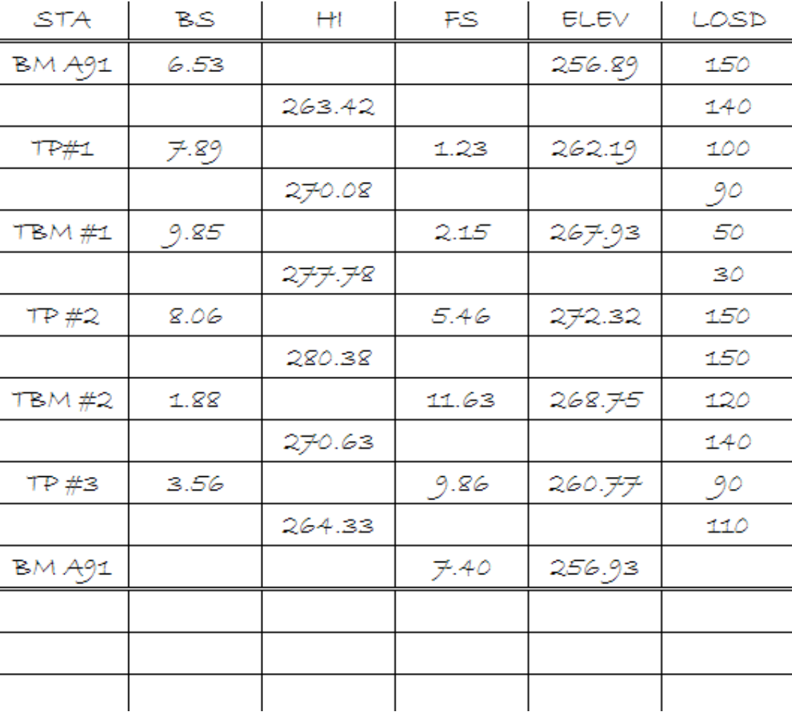
Leveling: Determining Elevations
ELEV1 + BS = HI
HI - FS = ELEV2
Example:
ELEV1 at BM A91 = 256.89’
BS at BM A91 = 6.53
256.89’ + 6.53 = 263.42’
263.42 = HI
Leveling: Determining Error of Closure
Error of closure = | MeasuredEndELEV - KnownEndELEV |
Leveling: Determining Allowable error
Allowable Error = 0.06√E
E = Distance of Loop in Miles