DC Circuits
 Call Kai
 Learn
Learn Practice Test
 Spaced Repetition
 Match
Match Flashcards
 Knowt Play
1/95

There's no tags or description
Looks like no tags are added yet.
Name | Mastery | Learn | Test | Matching | Spaced | Call with Kai | Chat |
|---|
No analytics yet
Send a link to your students to track their progress
96 Terms
Resistance
Relates to the flow of electric current that is subjected to friction.
This is the friction or opposition to the flow of current
It depends on four factors, these being: (a) the length of the conductor, (b) the cross-sectional area, (c) the type of material and (d) the temperature of the material.
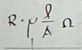
Formula for Resistance in terms of length and area
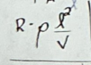
Formula for Resistance in terms of length and volume
Formula for Resistance in terms of volume and area

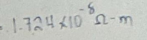
ρ, Resistivity of copper
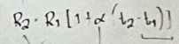
Formula for Resistance in terms of temperature
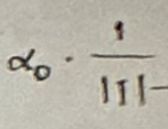
temperature coefficient, α
T - inferred absolute zero resistance temperature
Inferred absolute zero resistance temperature of copper, Cu
-234.5°C
Inferred absolute zero resistance temperature of aluminum, Al
-236°C
1. Carbon - Composition
2. Wire wound
3. Potentiometer
4. Rheostat
Common types of resistors include the following
Black values in resistance color coding
Value: 0
Multiplier: 0
Tolerance: ± 20%
Brown values in resistance color coding
Value: 1
Multiplier: 1
Tolerance: ± 1%
Red values in resistance color coding
Value: 2
Multiplier: 2
Tolerance: ± 2%
Orange values in resistance color coding
Value: 3
Multiplier: 3
Tolerance: ± 3%
Yellow values in resistance color coding
Value: 4
Multiplier: 4
Tolerance: -0, +100%
Green values in resistance color coding
Value: 5
Multiplier: 5
Tolerance: ±0.5%
Blue values in resistance color coding
Value: 6
Multiplier: 6
Tolerance: ±0.25%
Violet values in resistance color coding
Value: 7
Multiplier: 7
Tolerance: ±0.10%
Gray values in resistance color coding
Value: 8
Multiplier: 8
Tolerance: ±0.05%
White values in resistance color coding
Value: 9
Multiplier: 9
Tolerance: ±10%
Gold values in resistance color coding
Multiplier: -1
Tolerance: ±5%
Silver values in resistance color coding
Multiplier: -2
Tolerance: ±10%
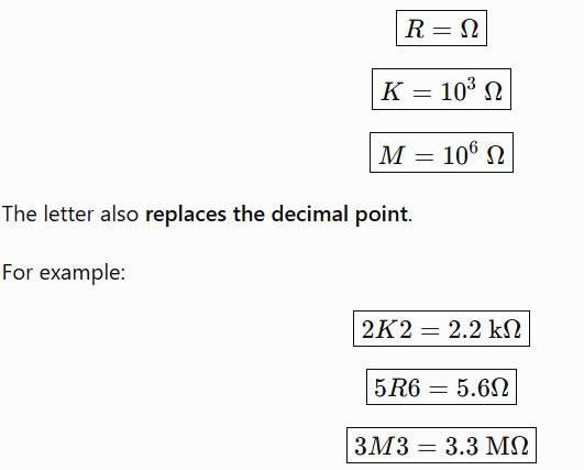
Key letters in BS 1852 resistance code formula
CONVENTIONAL FLOW
Electric charge moves from the positive side of the battery to the negative side
ELECTRON FLOW
Electron charge moves from the negative side of the battery to the positive side
Insulating material
In the carbon film resistors, the ceramic substrate acts as _____ to current.
Resistance between the opposite faces of a 1 meter cube at a specified temperature
Resistivity of a material is defined as the
Formula for current given area, charge, velocity, density
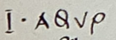
Ohm’s Law
The current is proportional to the applied voltage and inversely proportional to the resistance.
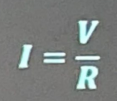
Electrical Power
• The time rate at which charged Q is forced to move by the applied voltage V.

V = Work (J) / Q, charge (C)
Formula of voltage in terms of charge and energy
Joule's Law
The power dissipated is directly proportional to the square of electric current and resistance
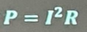
heat
Power loss is dissipated as ____ and can only exist in resistance
Network
Defined as the interconnection of components such as resistors and batteries forming a complicated circuit.
Node
Point of connection between two or more branches.
Branches
Defined as the part of the circuit or a certain network wherein an individual current flows; it is between two nodes.
linear
Semiconductors are not ___
1Watt-sec
1J is equal to
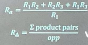
delta to wye
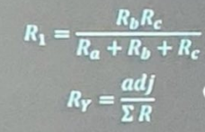
wye to delta
Kirchoff's Current Law
states that the algebraic sum of the current meeting at a point (or junction) is zero.

Kirchoff's Voltage Law
states that the algebraic sum of the potential rises and drops around a closed loop (or path) is zero.
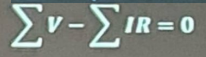
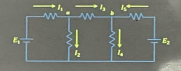
Nodal Analysis
Using this method, a circuit with "n" nodes, has a solution with only "n - 1" number of equations needed.
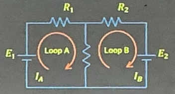
Maxwell's Mesh Method
This method involves a set of independent loop currents assigned to as many meshes as it exist in the circuit.
These currents are employed in connection with appropriate resistances when the KVL equations are written.
Superposition Theorem
In a linear circuit with several sources, the current and voltage for any element in the circuit is the algebraic sum of the current and voltages produced by each source acting independently.
The number of networks to be analyzed is equal to the number of independent sources.
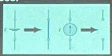
Turning off sources in Superposition Theorem (VSCO)
Voltage Source: Short
Current Source: Open
Thevenin's Theorem
Any two-terminal, linear bilateral dc network can be replaced by an equivalent circuit consisting of a voltage source and a series resistor
Short circuit analysis
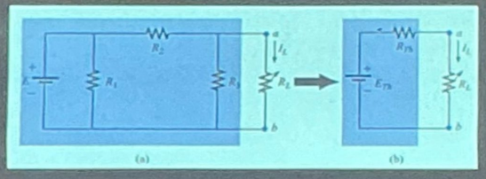
Norton’s Theorem
Any two-terminal linear bilateral dc network can be replaced by an equivalent circuit consisting of a current source and a parallel resistor
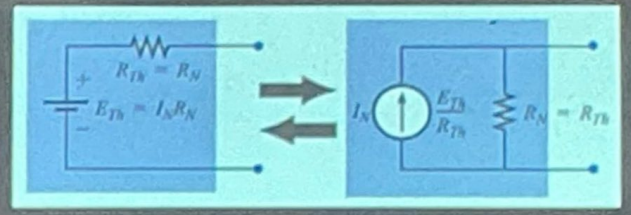
Steps in solving via Thevenin/Norton
1. Create an open output. Disconnect the load.
2. Turn off or Kill the sources. Use VSCO.
3. Solve for Rth/Rn.
Place back the sources.
Solve for Eth or In.
Formula of Power in terms of force and velocity
P=FV
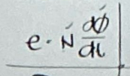
Formula for electromagnetic induction
Average current formula
2/π(Ipeak)
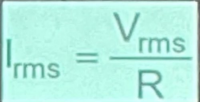
Effective/DC/RMS current formula
Ipeak / √2
Instantaneous Value
This is the value of voltage or current at any specific moment in time during a cycle. It changes continuously as the AC waveform progresses.
Peak Value (Maximum/Max)
This is the maximum positive or negative instantaneous value of the waveform.
Peak to Peak Value
The difference between the peak positive and peak negative values of the waveform
Average Value (Mean/DC)
The average value of an AC waveform is the mean of all its instantaneous values over a complete cycle.
In the case of a symmetrical wave, the average value over а complete cycle is zero. Hence, in their case, the average value is obtained by adding or integrating the instantaneous values of current over one half-cycle only
But in the case of an unsymmetrical alternating current (like half-wave rectified current) the average value must always be taken over the whole cycle.
Root Mean Square (Effective/AC)
This is the maximum positive or negative instantaneous value of the waveform.
Is a sine wave with an amplitude equals to the sum between the amplitude of the two input waves
If two perfect sine waves have the same frequency and the same phase, the composite wave:
An advantage of ac over dc in utility applications is the fact that
It can be easily obtained from dc generators
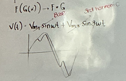
Composite wave
Wave that there is a presence of max value in instantaneous value
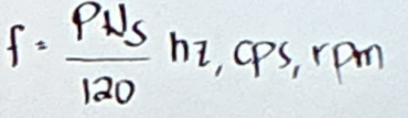
Electrical frequency equation for AC generators (Alternator)
P = number of poles
Ns = synchronous speed (rpm)
120 = constant from converting revolutions per minute to cycles per second
Form factor
RMS/AVE
Peak Factor
MAX/RMS
Purely Resistive Loads
Current is always in phase with the voltage
Phase difference is zero.
Storage elements
Inductor
Capacitor
Inductive Load
Current, I lags Voltage, V by 90°
Capacitive Load
Current, I leads Voltage, V by 90°
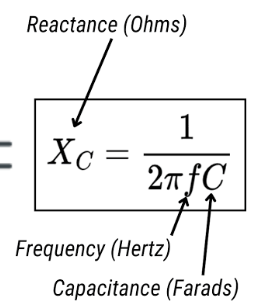
Capacitive Reactance
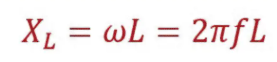
Inductive Reactance
Impedance formula
+ lag
- lead
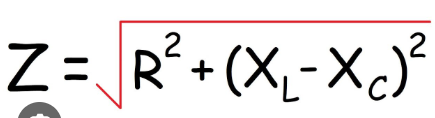
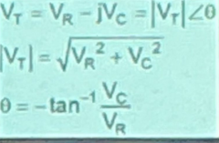
Voltage in Series RC
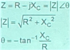
Impedance in Series RC
Purely resistive circuit
In simple series RLC circuit, _____ corresponds to infinite capacitance and zero inductance.
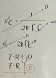
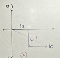
What is the phase difference between current in the capacitor and current in the resistor in a series RLC circuit?
0 degrees
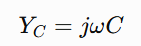
B is positive (opposite in impedance)
If admittance is given by Y = G + jB, and the circuit is capacitive, then:
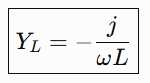
B is negative (opposite in impedance)
If admittance is given by Y = G + jB, and the circuit is inductive, then:
Conductance, G
Real part of admittance
Reciprocal of resistance
Susceptance, B
Imaginary part of admittance
Reciprocal of reactance
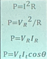
Active Power (P)
This is the "real" power that does work, like heating a resistor or powering a motor.
It's the average power consumed by the circuit over a full cycle.
Measured in watts (W).
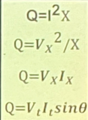
Reactive Power (Q)
This power oscillates between the source and reactive elements (inductors and capacitors).
It's not directly consumed by the load but is necessary for the operation of certain components.
Measured in volt-amperes reactive (VAR).
Does not do useful work in a circuit (non-consumable)
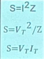
Apparent Power (S)
This is the total power flowing in the circuit, as seen by the source
It's the product of the RMS voltage and RMS current.
Measured in volt-amperes (VA).
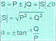
S = P + jQ
+ lag
- lead
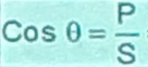
Power factor
cos theta = Real Power, P / Apparent Power, S
Current in reactive circuits
+ lead
- lag
Reactive Factor
sin theta = Reactive Power, Q / Apparent Power, S

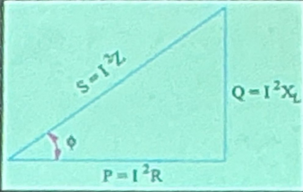
The Power Triangle
746W
1 hp is equal to
efficiency is equal to

Resonance
The tendency of a system to absorb more energy when the frequency of its oscillations matches the system's natural frequency of vibration (its resonant frequency) than it does at other frequencies.
XL = XC
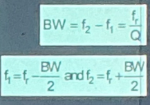
BW of Resonance
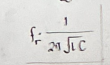
Resonant frequency
Series Resonant / Acceptor Circuit
Parallel Resonant / Rejector Circuit
2 types of resonant circuits
Series Resonant / Acceptor Circuit

Series Resonant / Acceptor Circuit
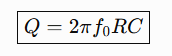
Q of Series RLC
ω = 1/√LC or numerator 2πfL
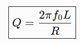
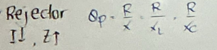
Q of Parallel RLC