Simulation Lecture, Lab, Block Cutting (ch21) REVIEW
 Call Kai
 Learn
Learn Practice Test
 Spaced Repetition
 Match
Match Flashcards
 Knowt Play
1/127

There's no tags or description
Looks like no tags are added yet.
Name | Mastery | Learn | Test | Matching | Spaced | Call with Kai | Chat |
|---|
No analytics yet
Send a link to your students to track their progress
128 Terms
Primary Purposes of Simulation
•Place patient in appropriate treatment position for area being planned and treated
•Assist the physician in the treatment planning process
•Establish and document appropriate volume to be treated
•Identifying the normal structures within or adjacent to the tumor volume
•Preliminary procedure of a patient treatment with radiographic documentation of the treatment portals
What is a CT Simulator?
•Dedicated CT scanner used for Radiotherapy treatment planning.
•CT Scanner is used to acquire a volumetric CT Scan of a patient which gives the “virtual” or digital information of the patient.
•CT simulation software provides virtual representation of the geometric capabilities of the treatment machine.
CT Simulation Components
1 Gantry
2. Bore aperture
3. Table/couch (table is made of carbon fiber)
4. Controls
5. Scanner lasers
6. LAP lasers (external lasers)
7. Remote control console and monitors
8. Virtual simulation/focal workstation (isocenter- where the doctor wants the beam to hit)
CT Simulation External Components
1. Couch Movement Controls
2. Emergency Off
3. Localizing Lasers
CT Workstation Console
1.Multiple monitors and controls for CT
•Patient data and info for each scan
•View and manipulate the reconstructed images before storing or transferring to virtual workstation
2.Virtual Workstation
•Ability to set isocenter for treatment field
3.Hardware necessary to produce high qualityDRRs (digitally reconstructed radiographs)
CT Simulator Data Acquisition
A. Axial
•Utilizes a fan-shaped beam
•Patient stays in a fixed position
•Tube rotates 360 degrees to capture a single transverse image
B. Spiral/Helical
•Involves volumetric scanning
•Captures more anatomy in the same timeframe
Reduces imaging duration
Helical scanning lessens the possibility of skipped anatomic data collection. (better for rad therapy)
Images may be visualized in any anatomic plane; axial, coronal, or sagittal
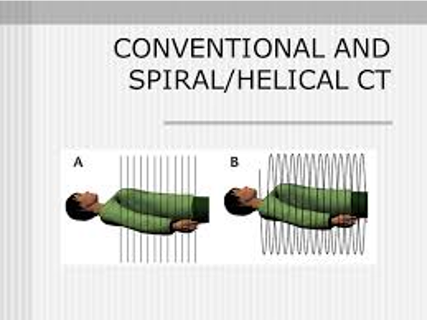
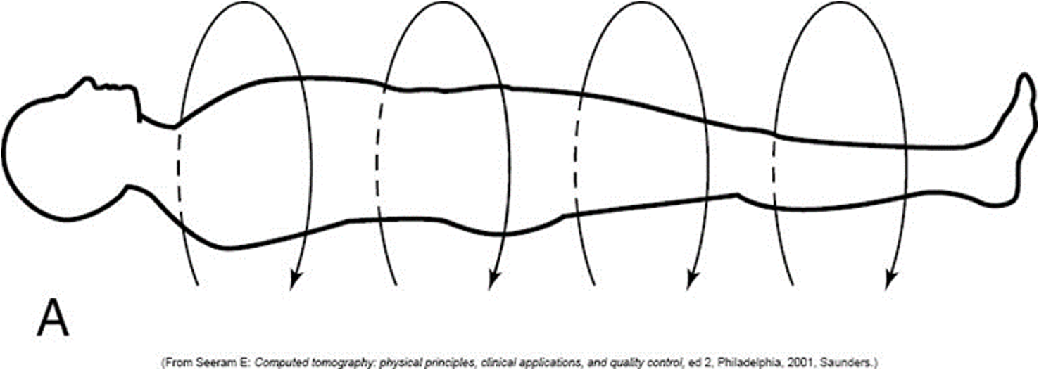
Axial Scanning
•Fan like beam (loaf of bread)
•Patient remains at a fixed point
•Tube rotates 360 degrees and collects a single image in the transverse plane
Spiral/Helical CT Simulator
•Volumetric scanning
•More anatomy included in same amount of time
•Shorter imaging times ( so better for patients in pain or that have breathing instructions)
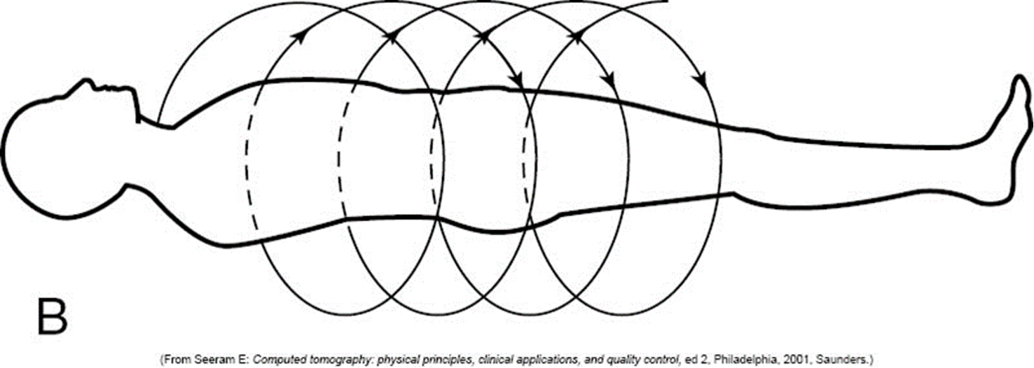
Continual Scanning
•Continual scanning and movement of table
•
Tube rotates continuously as patient moves through the scanner “slinky or coil effect
Pitch
is the distance the table moves between each slice.
is usually identified in departmental protocol
CT Laser
mounted on walls and ceilings of sim and tx rooms assist in localization. Lasers converge at the point of SAD or isocenter.
Patient marks are placed on the laser light to indicate where the iso is located.
Move in three different ways
XYZ COORDINATE SYSTEM
X – Sagittal axis separates right to left in the patient
Y – Transverse axis separating head to foot in the patient
Z – Coronal axis separating anterior/posterior in the patient
USED IN SIM
X
Sagittal (right to left)
Y
transverse (separates head to foot in patient)
z
coronal (separates anterior/posterior)
localization
Delineation of the tx target and the placement of the isocenter relative to the target is referred to as
Delineation=the act of clearly describing, drawing, or setting the boundaries of something
Marking the Patient
The isocenter marks and leveling marks must be recorded for reproducibility on the linear accelerator
Image reconstruction and Isocenter placement
•Check on patient
•Remind them to remain still
•Waiting for the physician to look over scan and place isocenter
•Information is then sent to LAP lasers
•Physician has selected the isocenter
•LAP lasers will shift to isocenter position in Sagittal(X) and Coronal planes(Z)
•Transverse plane (Y)
•Given a number to shift the table in or out
Laser Assisted Positioning (LAP)
Contrast Media & It’s Purpose
•Enhance the visibility of internal tissues for imaging
•Highlight abnormality
•Use Iodine, Barium or Air
•Oncologist depend on these agents to pinpoint target areas for radiation treatment planning
Patient History
Accurate patient history before administration of contrast is extremely important
•Name/Date of Birth
•LMP (Must be within 30 days)
•NPO status
•Past Medical History
ØDiabetes
o? Insulin
•Past Contrast Allergy
ØIs the Patient allergic to Iodine?
•Recent Labs
ØBUN (normal range 7 – 20 mg/dl)
ØCreatinine (normal range 0.5 - 1.2 mg/ dl)
Additional questions that may be asked
Prior surgery history
Prior history of cancer, recent chemo
Prior CT scans
Personal History of Renal Disease
ØChronic Kidney Disease (CKD)
ØHistory of Acute Kidney Injury (AKI)
ØPrior renal surgery / ablation
ØDialysis
Intravenous Contrast Sample Questionnaire
1. Have you ever received iodinated contrast media before?
2. Have you ever had a reaction to iodinated contrast media?
3. Do you have any allergies to food or medications?
4. Do you have any of the following conditions?
• Allergies (Have you had an allergic reaction to contrast in the past?)
• Asthma • Kidney problems • Cardiac disease
• Diabetes • High blood pressure • Sickle cell anemia
• Multiple myeloma • Pheochromocytoma
5. Is there any chance you are pregnant?
6. Have you had anything to eat or drink within the last 4 hours?
•Radiolucent-Negative Contrast Agent
•Low atomic number (Z) (radiolucent)
•Easily penetrated by x-rays
•Areas affected by contrast appear dark on CT scan
•Radiopaque-Positive Contrast Agent
•High atomic number (Z) (shows up white, radiopaque)
•Absorb x-rays
•Areas affected by contrast appear white on CT scan
•Create star artifacts on the CT scans
Atomic Number (Z)
•
•Based on the number of protons in the nucleus
•Higher the Z number-the more likely it is to absorb x-rays during CT scan
•High-atomic number contrast media can create star artifacts on the CT scans
•Oral (barium)
•Intracavitary (Rectally) (barium)
•
•Intravenous (IV) (omnipaque)
Contrast Media Administration used in Radiation Therapy
GI Tract Contrast
•Barium Sulfate
•not water soluble
•Most commonly used contrast agent for GI tract exams
•Delivered Orally & Rectally in a water-based suspension
•Coats lining of alimentary organs
•High atomic number Z=56
•Generates high level of contrast
•Low solubility protects the patients from absorbing harmful amounts of metal
•
•Gastrograffin-water soluble
patients with a high risk of gastrointestinal perforation would not receive barium sulfate and instead would receive an aqueous iodinated agent such Gastrograffin
Heavy Metal Salt
•Barium Sulfate
•Most commonly used contrast agent for GI tract exams
•Delivered Orally & Rectally in a water-based suspension
•Coats lining of alimentary organs
•High atomic number Z=56
•Generates high level of contrast
•Low solubility protects the patients from absorbing harmful amounts of metal
Barium Patient History Factors
Factor | Importance |
Age | Ability to communicate, hear, and follow directions ↑Risk of colon perforation caused by loss of tissue tone |
Diverticulitis or ulcerative colitis | ↑Difficulty in holding an enema ↑Risk of colon perforation |
Long-term steroid therapy | ↑Risk of colon perforation |
Colon biopsy within previous 2 weeks | Lower gastrointestinal series contraindicated |
Mental retardation, confusion, or dizziness | ↑Risk of aspiration during upper gastrointestinal series |
Recent onset of constipation or diarrhea | ↑Risk of colon perforation or tumor rupture |
Nausea and vomiting | ↑Risk of aspiration during upper gastrointestinal series |
Intravenous Contrast
Iodine
High atomic number (Z=53)
Absorb x-rays
Appear light gray to white on CT scan
Generally viscous, esp at room temperature
Injected using power injector
Proven to be one of the best contrast elements for imaging
Typically classified based on their chemical composition and influence of osmotic activity
Toxic to Kidneys
Iodine-based contrast materials are typically injected into a vein (IV)
Enhance the visualization of vascular organs and structures
Typically classified based on their chemical composition and influence of osmotic activity
Osmolality
measure of total number of particles in solution per kilogram of water
a low osmolatiry such as nonionic iodine decreases risk of side effects
Power Injector
Dual Syringe Injector
•Accurate injection of contrast and saline
•Offers various injection rates
•PSI (pounds per square inch)
•Measurements for patient safety
•300 psi pressure limit
Power Injector Steps
. Check to be sure the patient questionnaire was completed. Note any precautions as stated by the therapist, nurse or physician.
2. Have an anaphylactic kit on hand.
3. Retrieve appropriate contrast media from warmer.
4. Check expiration date of contrast to be injected. Do not use if expired.
5. Place syringe in power injector according to manufacturer specifications.
a. Remove covering of syringe. The tip of the syringe is sterile. Connect tubing to syringe by using sterile technique.
b. Remove air in syringe and intravenous line.
c. Connect to patient's intravenous site.
6Position and immobilize patient.
a. Select protocol for rate and amount of contrast to be injected. These are often predetermined based on the protocol for the department.
b. If a smaller needle was used in the patient, the rate of administration is decreased.
7. Prepare scanner. Do not begin scan yet.
8. Begin power injection.
a. Depending on what needs to be visualized, the scan will begin as dictated by the physician.
b. Some departments will not inject the contrast unless a physician or nurse is present.
Patient Prep for contrast
•May include
•Fasting
•Enemas
•Compliance
•Helps lead to diagnostic-quality images with least amount of contrast media possible
Contrast Reactions
Minor, Moderate, Severe
Minor Contrast Reaction
Resolve without any intervention
•Urticaria (hives)
•Limited swelling/edema
•Limited “itchy/scratchy” throat
•Nausea
•Retching
•Mild Vomiting
Moderate Contrast Reaction
More pronounced and require intervention
Fainting
Chest pain
Abdominal pain
Headache
Chills
Sever vomiting
Dyspnea (difficult breathing)
Extensive urticaria
Edema (swelling) of face and or larynx
Severe Contrast reaction
Life-threatening if not managed appropriately
Syncope (fainting)
Convulsions
Pulmonary edema
Life-threatening cardiac arrhythmias
Cardiac or respiratory arrest
Important points to remember:
• Have patients complete a questionnaire to identify any risk of a reaction to contrast
• Ensure patients have fasted if necessary
• Perform a CT scan without contrast and complete again with contrast for treatment planning purposes
Positioning Aids
•Very little structure with design
•Not Custom for patient
•Immobilize patient to prevent as much voluntary movement as possible
•Increases comfort but does not ensure the patient will not move
•Requires patient’s voluntary cooperation
•Most of these devices are used for more than one patient
Positioning Aids/Devices List
•Headrest
•Duncan (prone)
•Timo (solid)(Do not treat through)
•Silverman (Clear)(Treat through)
•Sponge
•Prone Pillow
•Accuform
•Thermoplastic Mold/Mask
•Closed Face (short/long)
•Open Face (short/long)
•Sframe Head Holder
•U-Frame Head Holder
•Wingboard
•Vaclok
•Breast Board (Supine Angle)
•Prone Breast Board
•Belly Board
•Sponges/Wedges
•Biteblock
•Shoulder Pulls
•O-rings
•Table Pad
•Knee Sponge
•Log
•Red Knee Sponge (Index)
•Angled knee sponge
•
Simple Immobilization Devices
Commonly used in addition to positioning aids
•Provide some restriction of movement and stability in cooperative patients
•Still does not prevent the patient from moving
•Can be used with more than one patient
•Cost effective
Has settings, but can use it on all patients
For example, knee sponge
Intermediate Immobilization Devices
Can be used with more than one patient
•The settings can be customized to the patient’s position
•Cost effective
•Commonly used with positioning aids
wing board, prone breast board, supine breast board
Breast Board Supine/Prone
•Adjustable settings on both of these
•Angled Breast Board used to help with larger breast that when lying flat the tissue falls up in the neck area. Using the angle allows gravity to help pull the breast tissue inferior away from the shoulder/neck area.
•Prone Breast Board used for breast where the tumor might be close or on the chestwall. This position allows the tissue/tumor bed to pull away from the chestwall decreasing lung dose.
Complex Immobilization Devices
Use most often with each treatment due to the complexity of treatment planning
•Each device is individualized
•More costly because some can not be reused
•Custom=Complex
Masks, bite lock (keeps tongue down while treating), Vaclok
Vaclok
•Vacuum pump and outer rubber bag filled with plastic minispheres
•Vacuum with fine mesh filter takes all the air out causing the minispheres to lock together around the patient position
•Vacuum procedure is complete when the bag is rigid
We reuse but its customizable
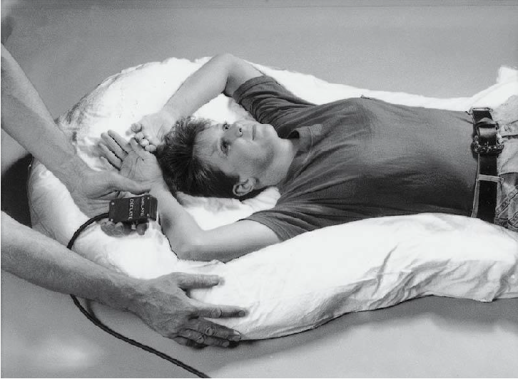
Indexing
•Improves setup accuracy and consistency from simulation to treatment across sessions
•Ensures precise patient positioning on the couch during treatment
•Allows dosimetry to enforce stricter tolerance in the record and verify process
•Reduces overrides
More consistent- makes patient be in same place everyday
Having the bar
What is index, what is not?
Index- makes it so the patient gets on the table every time vs if not indexed, the patient can move all over
Indexing
•The tabletop features several indentations labeled H3, H4, and so on
•H=head of table
•F=foot of table
This Sframe would be documented as indexed at H3
Allows for increased accuracy in treatment set-up reproducibility from simulation to treatment delivery
Linac
After the patient has completed the simulation process, a “dry run” is usually done the day before treatment starts.
“Sim and Start”
Sim and 1st treatment are done on the same day.
Reproducibility
Daily reproducibility is essential
•Patient’s age
•Weight
•General health
•Anatomic area to be simulated
•
All of these things matter in selecting positioning for effective treatment
If the patient is not (somewhat) comfortable and does not remain still during treatment administration,
then the sophisticated treatment plan and fancy immobilization devices are not effective
Some examples- someone with a broken shoulder cause of metastic cancer. Or older lady really skinny, need to put a pad on table to make more comfortable
Effective Immobilization
•Aids in daily treatment setup and reproducibility
•
•Reminder to the patient to remain still
•
•Should be of minimal discomfort to the patient
•
•Increases precision and accuracy of treatment on daily basis
Patient Positioning
One of the weakest links in treatment planning is …
•Advancements in medical imaging
ADVANCEMENTS – Image fusion is often used on modern planning.
•Radiation oncologists define the target not just in 2 dimensions but also in 3 and 4 dimensions (4th being motion).
IGRT & IMRT allow dose escalation
•Goal of radiation therapy and simulation procedures
In many cases, the ultimate success of treatment is directly related to the effectiveness of the simulation procedure. This procedure determines and documents patient immobilization and positioning for their course of treatment.
Intensity-modulated radiation therapy (IMRT)
treatment technique. can modulate intensity of beam within a tumor volume. Allows us to give more dose to certain areas
Image-guided radiation therapy (IGRT)
before treating patient, you need to image right before beam on
Usually IMRT and IGRT go hand in hand
Localization-
used to identify the tumor (usually done with CT scanner) helps determine what angles to deliver the dose
Contour-
outline structures/ tumor
OARs-
Organs at risk
Verification-
makes sure treating correct tumor
Radiopaque marker-
helps define where we want to expose
Separation-
want to know the thickness being treated: from where the beam will enter to exit: can use calipers, but usually done with CT scanner
Field size
size of treatment area
Interfraction motion-
any motion (especially as changes come as treatment goes on) if patient is in more pain etc
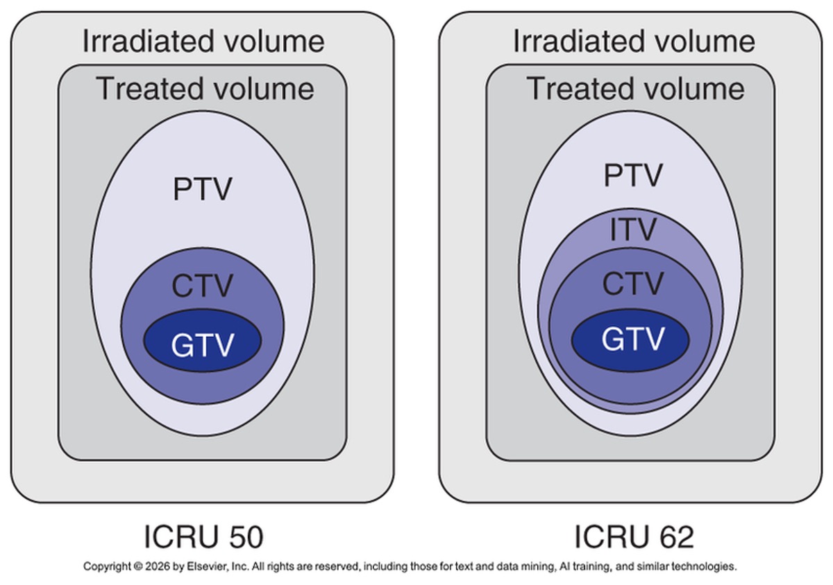
GTV
Gross Tumor Volume
CTV Clinical Tumor volume
cancers can potentially grow outward, so we want to include this area in treatment
PTV
Planning target/tumor volume
Do we still use conventional simulations?
yes
•Conventional simulations
Designed to simulate:
•Mechanical factors
•Geometric factors
•Optical conditions
CONS:
Fluoroscopy-based simulations
Physical measurements
2D imaging
EPID (Electron portal imaging device)
replaced the fluoro tube on the conventional simulator
CT Sim or Virtual Sim
•View of anatomic data in 3 dimensions
•All tissue densities are easily visualized and manipulated
•Much more efficient
Simulation
should define the anatomic area to be treated so that it is reproducible for daily treatment. An elaborate and complicated simulation is of no value unless it is reproducible on the treatment unit.
Simulation Procedures
•Team approach
•Equipment requirements
oCT scanner with fast acquisition time, multi-slice technology, axial and helical scanning capability, and a wide bore larger than 75 cm, flat couch top
oOther options include gating technology (4DCT) and SGRT technology
•Verification of a treatment field- The localization and verification of a treatment field during CT simulation must reflect precisely what will happen in the treatment room when a prescribed dose of radiation therapy is delivered.
•Immobilization
•Policies and procedures
Benefits of CT Simulation
•Outline critical structures
•Delineate target volume
•Achieve optimal beam placement
•Boost fields planned without patient present (treats just small field within a field)
•Beam’s eye view (BEV)- (looking at the tumor field from the view of the beam)
•Electronic field shaping
•Construction of digital reconstructed radiographs (DRRs) (Digitally reconstructed radiograph)
•Calculation of dose distribution
BEV (beams eye view)-
looking at tumor field from the view of the beam
Boost field-
treats small field within a field
Considerations and Limitations
of CT Simulation
•Bore size (depends on what immobilization device used and position)
•Width and shape of couch
•Laser system (isocenter)
•Acquisition and patient marking time (better than in conventional sim)
•CT numbers in dose inhomogeneity corrections
•Setup parameters and treatment accessories unable to be verified
•Must visualize entire contour (need to make sure nothing is bumping up against scanner)
the more immobilization for safety and accuracy
The higher the dose
•Special Procedure Immobilization
Stereotactic radiosurgery
Stereotactic body radiation therapy (SPRT) (anywhere to 5 treatments, with super high dose)
Computed Tomography Scans (1 of 5) POSITIONING
•Patient Positioning
Lock patient and immobilization device into place on the table.
Position patient carefully with the treatment area in the center of the CT bore and scan field of view.
For diagnostic CT imaging, FOV offsets are common.
Clinically straighten the patient by using the external laser system and any useful topographic anatomy. Temporary reference marks can then be drawn on the patient.
Know if the immobilization should and can fit through the bore of the CT scanner.
Computed Tomography Scans (2 of 5)
•Topograms (scout)
The first images acquired during the CT simulation
It may be an AP scan, lateral scan, or both
Used to assess alignment of the patient in the CT bore
Geometric tools in the scanner software aid in patient readjustment
•Data Acquisition
Select an appropriate scan protocol (usually site specific) with parameters (that may be adjusted)
Once CT images have been acquired, they are exported via DICOM and imported into simulation software
Topogram
AKA surviews, pilots, scouts, scanogram images
•Methods of Simulation With Computed Tomography Images
Shift Method
No-Shift Method
Techniques for Isocenter Localization
Integration With Treatment Planning
Shift method-
have to go a certain distance because it is not marked
No-shift method-
line up at original marks. The doctor lines up and marks it
Computed Tomography Scans (5 of 5)
•Patient Marking System
Isocenter or field edge marking systems are available for CT
Using temporarily marked reference points, the computer calculates the isocenter with reference to the temporary marks
ØLAP laser company’s CT positional laser system
•Documenting Data
Organized per institutional standard
Immobilization devices must be documented
Also recorded: exact field size, gantry position, shielding, and isocenter
Completed treatment plan is exported in the record-and-verify system
DOCUMENT IN PICTURES AND WRITING
Use of Four-Dimensional Computed Tomography in Virtual Simulation
•Respiratory Gaiting
Breathing motion artifacts
Four-dimensional scanning
Spirometer
Maximum intensity projection (MIP)
•Surface Imaging in Radiation
•Magnetic Resonance Imaging in Simulation
•Magnetic Resonance Imaging—Only Simulation
•Positron Emission Tomography-Computed Tomography Imaging
Respiratory Gaiting-
how much does the tumor move while breathing so we know how much to treat
Room Design
•Space Allocations
The room should accommodate the machine, its components, and its full range of motion.
Space should be allocated for a good-sized counter with sink, workspace, writing area.
There should be ample storage for simulation equipment, spare simulator parts, and immobilization devices.
The control area should be large enough to house several pieces of equipment, a work area, and several personnel.
•Other Considerations
Appropriate room ventilation per simulator manufacturer
Correct lighting system that is adjustable
CT simulator external positioning and patient marking lasers
Shielding design
Quality Assurance
•AAPM Radiation Therapy Committee Task Group 66
•Daily warm-up and QA
•Monthly QA
•Yearly QA
Electrons block
treat more superficial

Photon blocks
penetrate deeper
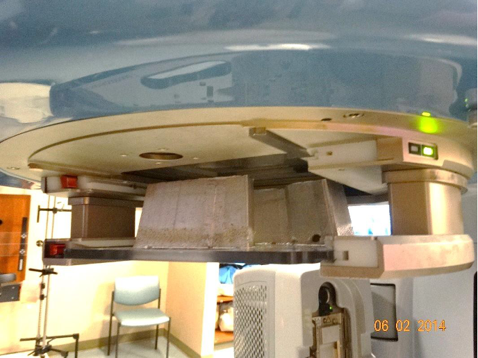
STD
Source to tray distance
Electron block
lThickness is much less-not as much block is needed because the energy used is lower
lThere is NO divergence
lSource to Tray Distance (STD) is 95cm.
Photon block
lMuch thicker block is needed because you are using stronger energy
lThere is divergence.
lSource to Tray Distance (STD) is 60-65cm.
Positive or Negative
**The acceptable range (%) of beam transmission through a block is 2-5%
Positive block-
when an actual structure is blocked
so we are treating everything around what is blocked
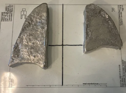
Negative Block-
block-blocking everything except the area to be treated. Ex Primary brain, electron

Electron field blocking
lCustom cutouts
lStandard cutouts
lLead
Electron Beam Accessories
1.Cones – limited to a few select sizes
2.Electron cutouts – Custom made to collimate and shape the treatment field
3.External shields – Placed to shape and protect critical structures
4.Internal shields – Tissues directly in front of the shield may receive 30% to 70% higher dose. Internal shield must be covered with low atomic # material to reduce backscatter ex. Eye shields, dental wax
5.Tissue Compensator – even out irregular surface placed directly on patient (bolus)
Internal shields-
shields- put lead inside for example for a eye or nose so the radiation doesn’t keep going
Decreases irritation