Electronics - Chapter 2 - Diode
1/33
There's no tags or description
Looks like no tags are added yet.
Name | Mastery | Learn | Test | Matching | Spaced | Call with Kai |
|---|
No analytics yet
Send a link to your students to track their progress
34 Terms
What is a diode
semiconducting components with 2 semiconducting parts: n-region (negative) containing mostly electrons and p-region (positive) containing mostly holes.
Reverse-bias p-n junction
connecting (-) of voltage supply to p-region and (+) to n-region.
as holes accumulated at the border of the weak region of n-reg → (-) carriers flush in and the same for (+) carriers at p-reg → widening the weak region.
→ weak region has very small amount of electricity carriers → very small nearly to 0 current can pass through.
→ saturated and small current → diode locked.
Forward-bias p-n junction
connecting (+) of voltage supplier to p-reg → neutralize the electrons at the border of weak reg of p-region and the same for n-region → narrow the weak region → allow greater current to pass → since the flow is rapid → current increases exponentially
Formula for current passing through Diode


What is this
Current flowing through Diode in Reverse-bias state → very small and saturated → [10^(-8), 10^(-12)] (A)

What is this
Voltage diff at 2 ends of the Diode

What is this
Temperature coefficient → 0.026 V
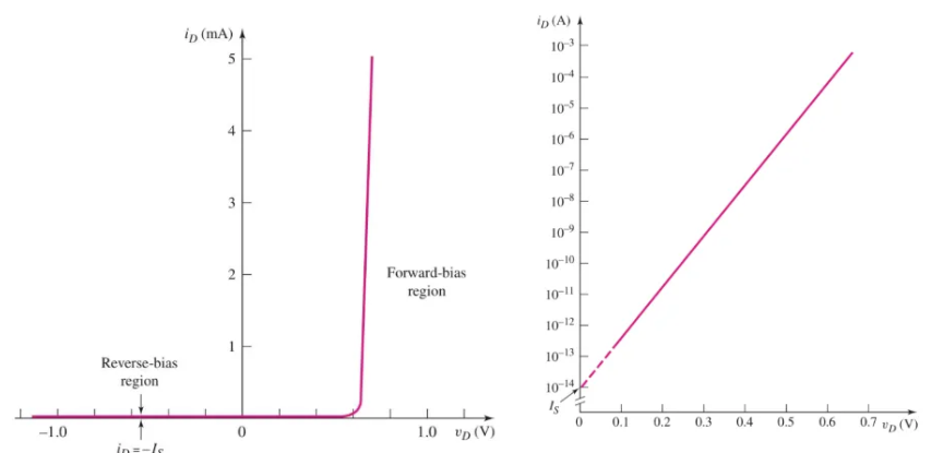
What is this graph representing
Characteristic line of relationship between current-voltage → y-axis is curent flowing through diode, and x-axis is voltage of diode
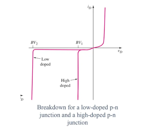
Breakdown voltage
Is when we increase the voltage that creates reverse-bias for the diode → reaches a point V0 that will cause the ID to grow exponentially → break the diode
Redraw the CC diagram to equivalent diagram of _ CC when diode is in reverse-bias
open
Redraw the CC diagram to equivalent diagram of _ CC when diode is in forward-bias
short circuit (ngắn mạch)
Output AC signal if the diode is in forward-bias
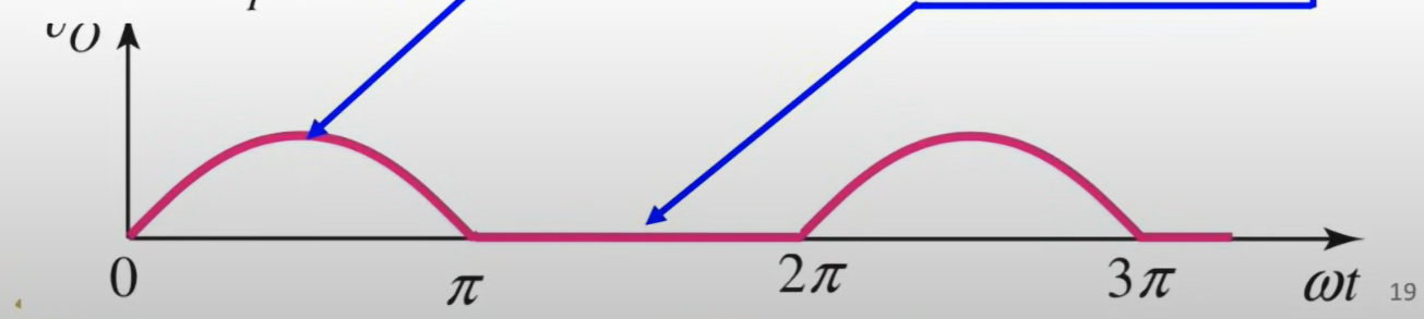
Why the AC output signal has its negative phase flat?
Since Diode will lock/reverse-bias → prevent current to pass when Vd < 0 → negative phase of AC
Iteration technique
Having the equation Kirchoff’s voltage that is in terms of Vd → Insert each random value for Vd to see if there is any value that satisfies the equation
Graphical Analysis
Upon having the Kirchoff’s voltage equation, let Vd = 0 and Id = 0 → have 2 points → create a line connecting 2 points → load line
From the point of Vd that causes the Id to increase exponentially → draw a line vertically at that point → cross the load line and draw a horizontal line at that intersection to y-axis to ESTIMATE Id.
Piecewise linear model
Approximate the characteristic line at region of reverse-bias and region of forward-bias
(PLM) At region of forward-bias, the characteristic line:
approximate a straight line with a slope of 1/rf. However, in most cases, rf will let to be = 0 (if rf ≠ 0, problem must already give out data) → the line will become a straight one, perpendicular to the Vgamma point (threshold activating forward-bias)
How to determine ID in PLM
Upon having the characteristics line perpendicular at the point Vd = Vgamma, draw the load line → the intersection of those 2 will be the Q-point → at Q-point in y-axis we will have Id.
If Vinput for the CC is great enough for the diode to forward-bias, V falling on the diode will
equal to Vgamma
If Vinput for the CC smaller than Vgamma
reverse-bias → Id = 0 and Vd = 0 → open CC
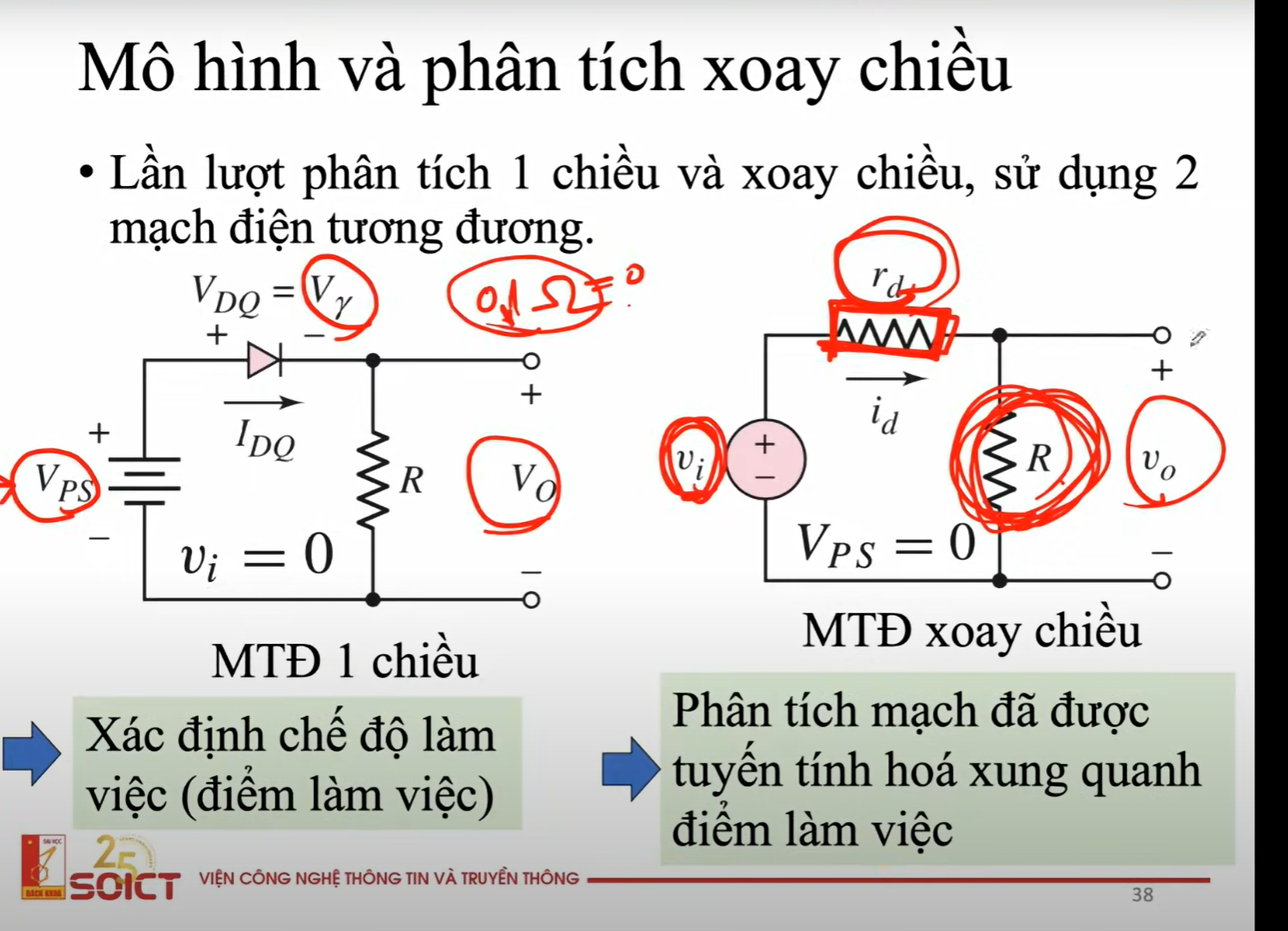
To analyze a CC with diode:
Firstly, DC analyze the CC with DC components to determine the Q-point
Then, AC analyze AC components → consider DC components as wires.
The V output and I output of the problem will be the sum of Vdc and Vac, and Iac and Idc.
DC input V is ___ and AC input V is ___
large / small
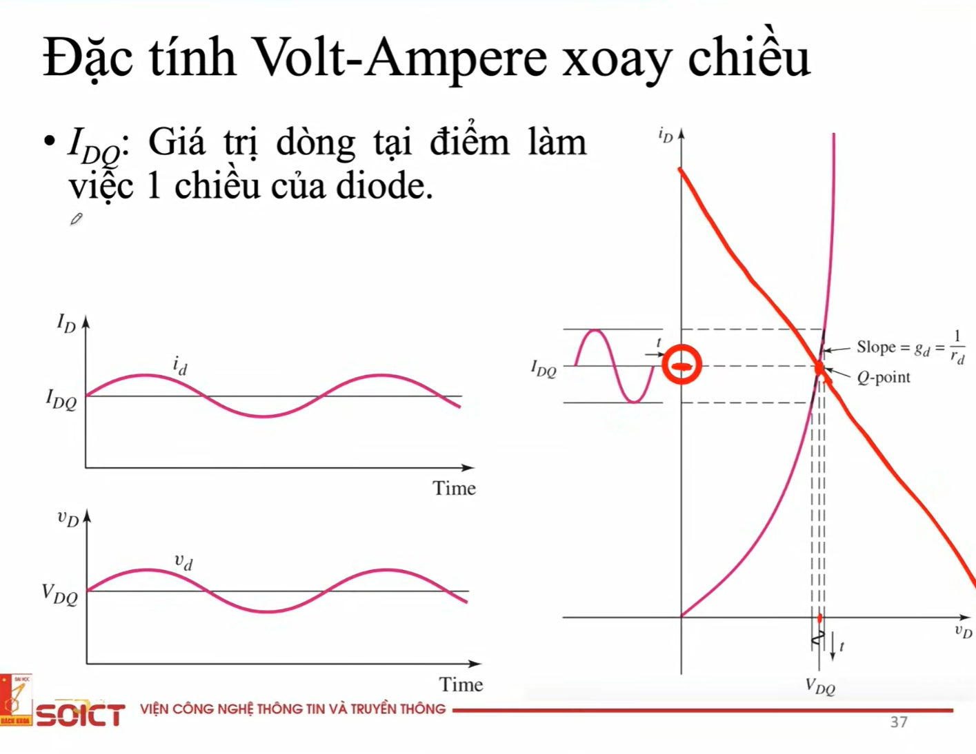
Why Q-point is important in CC with diode analysis?
From DC analysis, we can determine Q-point (intersection of characteristics line and load line).
At that Q-point, with respect to Vd-axis, we can determine the AC Vd input signal, which is VDQ.
At that Q-point, with respect to Id-axis, we can determine the AC Id output signal, which is IDQ - value of Id at the Q-point.
Diode in DC analysis of the CC
Short CC with VDQ falling on the diode = Vgamma, and AC V will be removed.
=> Voutput will be V falling on R

Diode in AC analysis
Because each component has a small amount of self-resistance, and since AC Vinput is a small signal, that resistance amount becomes a problem → we redraw the CC into an equivalent CC with Rd → resistor of the diode.
=> Voutput will be V falling on R
In forward bias in terms of Linear Piecewise Model, we will redraw the CC into an equivalent CC with
the diode becomes a separated Vgamma voltage supplier and resistor Rf (resistor