kettering image production (MG)
1/248
There's no tags or description
Looks like no tags are added yet.
Name | Mastery | Learn | Test | Matching | Spaced | Call with Kai |
|---|
No analytics yet
Send a link to your students to track their progress
249 Terms
kVp (kilovoltage peak)
A) is an influecing factor of radiographic receptor exposure. increases in kVp will increase receptor exposure until 100 percent of the beam is successful in reaching the image receptor
b) increases in kVp increases the percentage of beam penetration through a given body part that will increase the amount of radiation reaching the image receptor
15 percent rule
a 15 % increase or decrease in kVp, keeping all other factors constant, will result in a doubline or halving of radiographic receptor exposure.
example: it is determined that an underexposed abdominal radiograph needs to be repeated with exposure factors doubled. if the original exposure factors were 70 kvp at 32 mas, what new kVp should be used to improve this radiograph?
70 x 0.15=10.5
70 + 10.5= 80.5 kVp
Grid ratio formula
Grid ratio = h/D
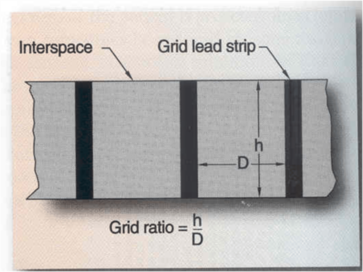
if no adjustment in techneique is made, as grid ratio increases radiographic receptor exposure will_____
decrease
grid ratio bucky factor
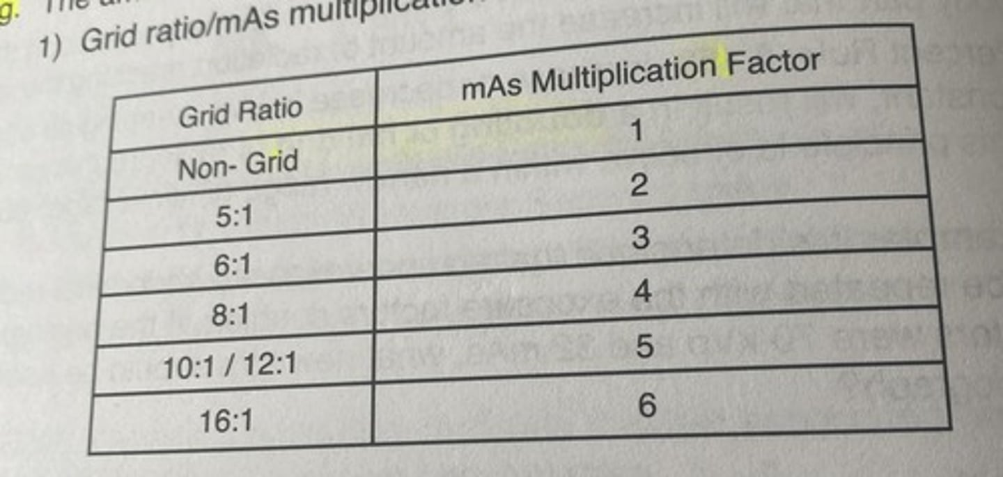
grids
-are beam attenuators
-if no adjustment in technique is made, as grid ratio increases receptor exposure will decreases
-to maintain a desired amount of radiographic receptor exposure, changes in mAs are required to compensate for the presence of a grid between a patient and a image receptor
filtration (photographic factor)
a) filters are beam attenuators; decrease skin exposure to the patient
b) as the amount of filtration in the path of the beam increases the amound of radiation available to expose the image receptor will decrease, resulting in a decrease in radiographic receptor exposure
factors that contribute to the absorbing ability of a given body part include
1) thickness
2) atomic number
3) specific gravity
thickness
as thickness increases beam attenuation increases and receptor exposure will decrease
atomic number
as the atomic number of an object increases attenuation will increase yielding a decrease in radiographic exposure
specific gravity
as specific gravity (comparison of the receptor exposure of an object to water) increases attenuation will increase yielding a decrease in radiographic exposure
additive diseases will increase the amount of the beam attenuation of the objects involved, and will result in a corresponding
decrease in radiographic receptor exposure
destructive diseases will decrease the amount of beam attenuation yielding an
increase in radiographic exposure
beam restriction
increasing collimation or beam restriction results in decreasing field size, decreasing radiographic receptor exposure and also decreasing the amount of scatter reaching the IR
destructive diseases
decreased subject receptor exposure, increased radiographic receptor exposure
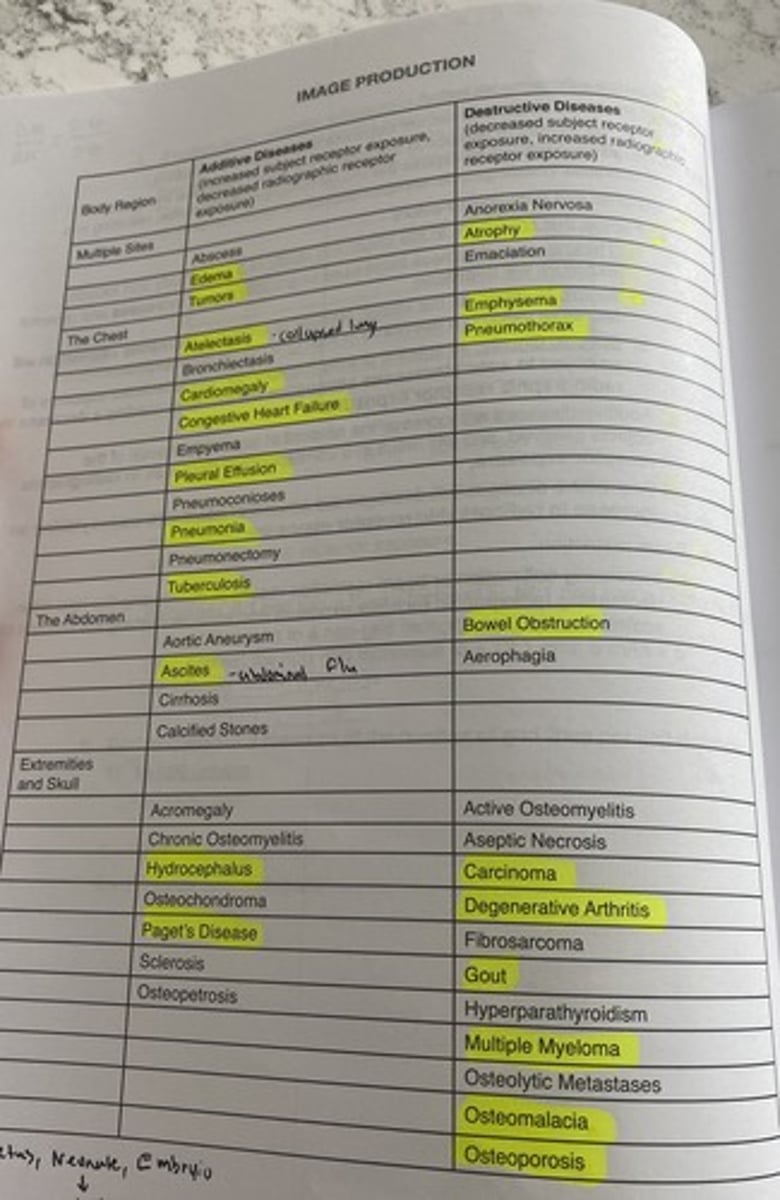
additive diseases
increased subject receptor exposure, decreased radiographic receptor exposure

annode heel effect
-variation in x-ray beam intensity with an increase in beam intensity toward the cathode end of the beam and a decrease intensity toward the anode end of the beam
-AP T-SPINE, AP FEMUR
FAT-CAT
when needed, place the thickest portion of the anatomy (FAT) toward the cathode (CAT) end of the beam
kVp
a) is the primary controlling factor of SUBJECT contrast
-rate of attenuation of different body parts
umbra
area of image sharpness
blur or penubra
are of unsharpness surrounding the image
*aka geometric unsharpness
*geometric unsharpness is always brighter on what end of the beam?
cathode side of the beam
*straight OG
OID: obect ot image reciever distance (geometric and photographic factor)
a) effects recorded detail and magnification (size distortion) by allowing an increase in divergance of the remnant beam prior to reaching the IR
b) as OID Increases recorded detail decreases
SID: source to image reciever distance (geometric and photographic factor)
a) effects recorded detail and magnification (size distortion)
b) as SID increases , recorded detail increases, while magnification decreases
actual focal spot size
the size of the area on the anode target that is exposed to electrons from the tube current
effective focal spot size
refers to the focal spot size as measured directly under the anode target
line focus principle
Describes the relationship between the actual and effective focal spots in the x-ray tube. A smaller target angle produces a smaller effective focal spot.
distortion
1) deals with the defgree of pervasion or "untrueness" of the image recorded on the image receptor
2) types of distortion include size distortion(magnification) & shape distortion (elongation and foreshortening
shape distortion
-angulation of the tube, angulation of the part, angulation of the image receptor, and motion
size distortion
-limited to changes in Object to image reciever and source to image reciever distances
-OID AND SID
technique charts
1) pre programmed techniques- anatomically programmed radiography (APR)
a) technique charts are programedd into the control unit
b) the technologists selects an anatomic display of the part and the microprocessor automatically selects the appropriate kVp and mAs
fixed kVp chart
a) also known as a variable mAs chart
b) pre established kVp value is used for each body part
variable kVp chart
a) also known as a fixed mAs chart
b) pre-established mAs is used for each body part
c) kVp is determined by using calipers to accurately measure thickness of the body part being evaluated
d) typically, a 2 kC change is made ofr each cm in part thickness when operating at 80 kvp
wet plaster casts
usually recquire a doubline of exposure factors: either a 100% increase in mAs or an 8-10 increase in kVp
dry plaster cast
usually requires either a 50%-60% increase in mAs or a 5-7 increase in kVp
fiberglass
usually requires a 25%-30% increase in mAs or a 3-4 increase in kVp
part thickness
as a general rule, parts measuring greater than 10-13 cenetimeters require use of a grid to offset the production of secondary and scattered radiation in the volume of tissue as the x-ray beam passes through the tissue
Automatic Exposure Control (AEC)
Device that terminates the exposure when a specific quantity of radiation has reached the image receptor (IR).
effects of changing exposure factors on radiogrpahic quality
a) higher kVp techniques will result in a reduction of radiographic contrast
b) higher mAs rechniques will result in a longer exposure time and possibility of motion on the resultant radiograph
c) quantum mottle may occur with AEC techniques if the recquired mAs is to low-this can be prevented by decreasing kVp which will result in an increase in mAs
detector selection
-phototiming cell or field that is selected depends on the part under examination
-if the central ray is directed to the part under examination ex: an ap projection of the hip, the centr cell should be selected
-an exception to this rule is a PA projection of the chest: selecting the center cell will place tit over the heart and may result in over penetration of the lung fields
-bc of this, an outside cell(s) may be selected for a PA chest radiograph
anatomic alignment
-since the amount of radiation required to produce a quality, diagnostic radiograph depends on the cell that is selected, careful positioning and central ray centering is required when using AEC techniques
Exposure adjustments (density +1 or -1)
a) the receptor exosure of a radiograph produced using AEC techniques may be influenced by adjusting the receptor exposure control
b) for very thing patients or pediatrics a negative receptor exposure contral may be selected to help prevent overesposure
c) for very large patients a positve receptor exposure control may be selected to help prevent underexposure
how does a technologist adjust the rate of exposure when using an AEC device
*adjust the density control
spatial resolution
-is the ability of the system to record adjacent small structures
-the sharpness of the structural edges record in the image
-measured in line pairs per mm (lp/mm) <-straight player
pixel (picture element)
1) smalest area depicted in an image
2) two-dimensional sqaure that contains discrete grey shade
3) size-measured end to end
*as pixel size increases, spatial resolution??
decreases
-vice verse if pixel size decrease SR increases
pitch
-measured center to center
as pixel pitch increases, spatial resolution??
decreases
pixel density
-number of pixels per millimeter
-determined by the pixel size and pixel pitch
-as pixel size decreases, pixel density increases, thus SR increases
DEL (detector element) size
-size used with direct capture radiography (casette less)
-uses a flat panel detector(IR used in DR)
-spatial resolution is determined by the detctor element size (DEL)
-DR uses detector element size
-pitch
As DEL increases, spatial resolution ____?
decreases
fill factor
a ratio of a pixels light sensitive area versus a pixels total area
as fill factor increases, spatial resolution ___
increases
matrix
-two dimensional array of pixels ("x" and "y")
-matrix size is the total number of pixels
-matrix size is dependent upon FOV and pixel density
a)example 35 cm x v43 cm at 5 pixels/mm
--350mm x5 =1750
--430mm x5=2150
--2150x1750=3,762,500 pixels
increase image recpeptor size results in increase in ??
matrix size
Decreasing pixel size results in ___ matrix size and ___ spatial resolution
-increased
-increased
sampling frequency
-the number of pizels sampled per millimeter as the laser scans each line of the imaging plate* main controlling factor of spatial res. in CR
1) the more pixels sampled per millimeter the greater the sampling frequency
2) the greater the sampling frequency, the longer it takes to process the plate due to the amount of information being collected
3) in some systems, using a smaller IR permits more pixels per MM to be scanned yielding improved image quality
4) increasing the sampling frequency results in the laser moving a smaller distance and there is an increase in spatial resolution
5) CR uses sampling frequencey
nyquist frequency
- The relationship between the sampling frequency (number of pixels/mm scanned by the laser, at a rate of 2x the highest frequency present) and the spatial resolution (resulting image detail, sharpness, etc...
what is the min. rate at which signal can be sampled w/o introducing samples?
2x the highest frequency
contrast resolution
-ability to detect subtle changes in the gray scale
a) bit depth
b) Detective Quantum efficiency (DQE)
c) beam restriction
Signal
-results from x-ray deposition of energy in a detector (image data)
noise
results from extaneous information (interferance, limits the ability to visualize objects
contrast resolution/dynamic range
range of values over which a digital image receptor will respond; greater dynamic range will yield greayer contrast resolution
dynamic range
-series of exposure values used to produce acceptal image.
-the lightest lights to the darkest darks that can be seen
exposure latitude
-ability of a system to both over and under expose yet still produce an acceptable image
-exposure latitude as a range within the dynamic range
quantum noise (quantum mottle)
results when to few x-rays reach the IR- underexposure, the IR is photon starved and is related to the IR photon intensity
-increased intensity results in decreased noise, and decreased intensity results in increased noise
scatter noise
A refraction of X-ray beams away from the original beam path; if this refraction reaches the detector, it can result in unwanted radiation exposure on the image, which degrades the image & makes it more difficult to interpret.
electronic noise
Random signal fluctuations in an electrical signal; characteristic of all electronic circuits.
Signal to noise ratio (SNR)
-ratio between "signal" or meaninful information and "noise" or background information
SNR
-as noise increases it is more difficult to visualize small objects
a) it is desirable to have a high SNR
b) NOISE IMPACTS THE PRECEPTIBILITY OF SPACIAL RESOLUTION
e) noise decreases are ability to see all spatial resolution and contrast resolution on an image
basic information that must be present on the radiograph
-patient data: name & identification number
-examination data: including postural and side markers
-examination date: date exam was performed
-institutional data: hospital/clinic name where exam was performed
what gives the best SNR?
a) 121: 11
b) 8 :1
c) 49: 7
d) 5: 2.5
a) 121: 11->11:1
b) 8 :1
c) 49: 7-> 7:1
d) 5: 2.5->2:1
a minium mAs change of ___% is neccesary to yield a noticable receptor exxposure change within the radiographic image
30 %
Grids
used to control scatter reaching the IR
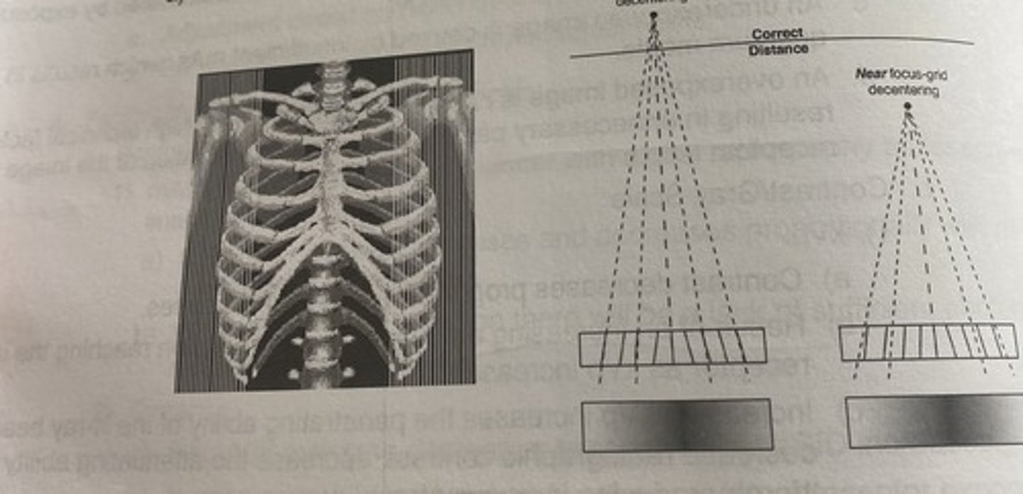
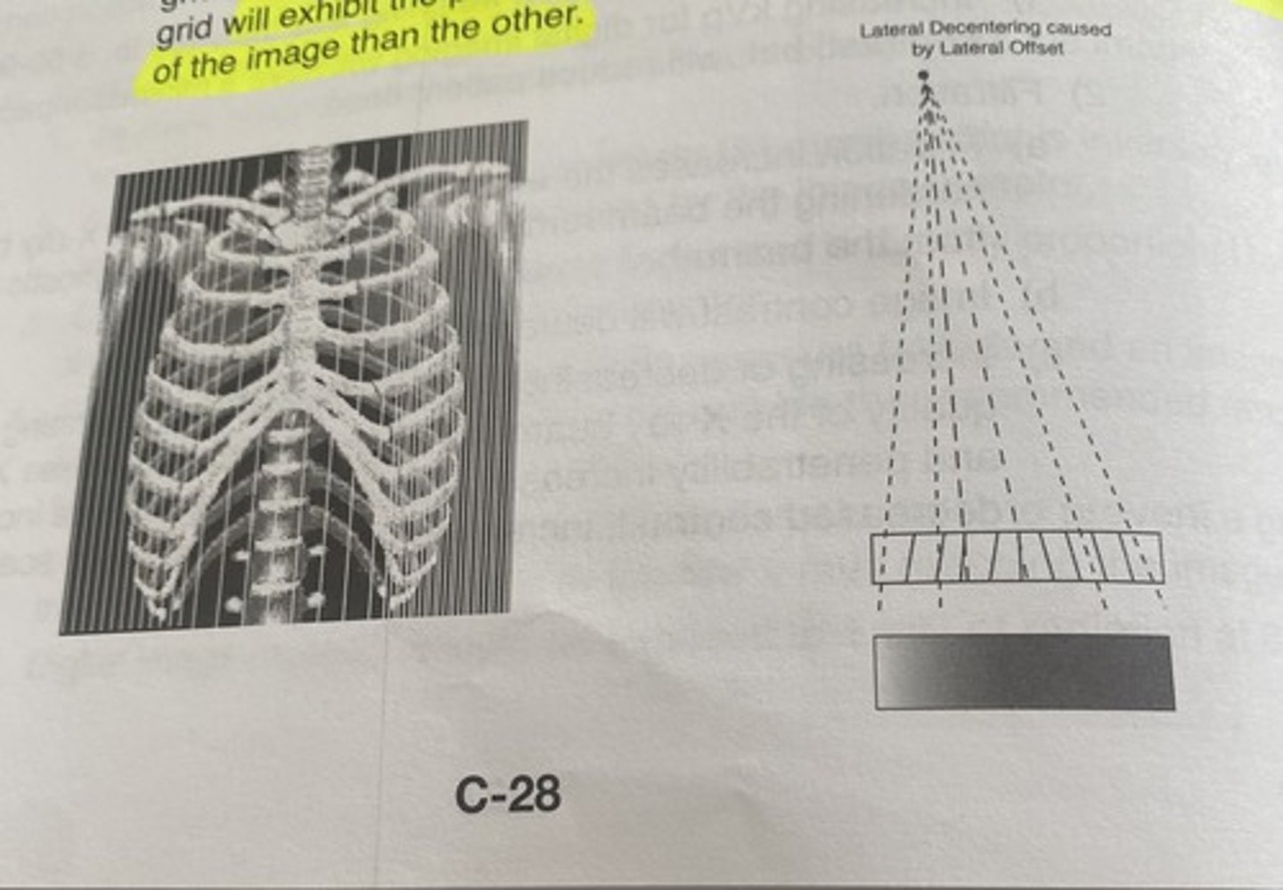
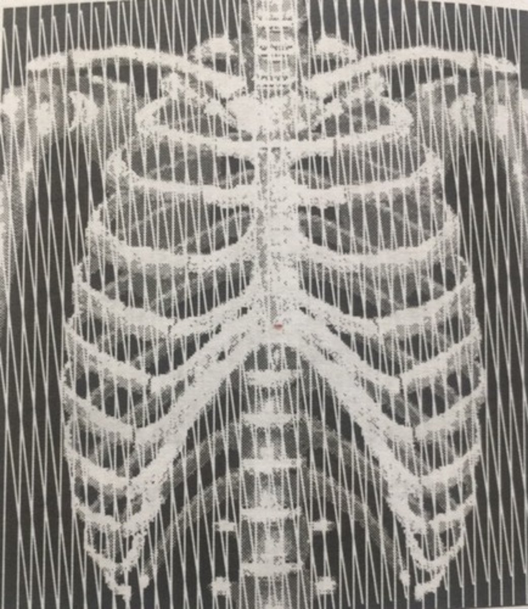
Grid focus distance decnetering
using a grid outsid ethe established focal range will exhibit uniform cutoff along the lateral edges of the image
lateral decentering
Lateral off-centering of the central ray to a focused grid angulation of the central ray across the transverse axis of a focused grid will exhibit the presence of lead strips of more frequency on one side of the image than the other
moire pattern
-occurs when two linear grids are placed on top of one another to make upa crosshatched grid, but the lead lines are not aligned at right angles to one another
recorded detail/spatial resolution: motion
a) recorded detail decreases as patient motion increases
b) voluntary motion must be controlled when the radiographic procedures demands it
c) short exposure time will help minimze the effects of voluntary and involuntary patient motion
size distortion
a) image magnification is increased by a long OID and/or a short SID
b) a short OID is the best way to minimize the effects of voluntary and involuntary patient motion
shape distorion
affected by angulation of the bubel angulation of the part, angulation of the image receptor and motion
Ghost image
Caused when there is insufficient erasure of an image and a ghost image is seen on the new image
** CR ONLY **
xray tube construction: KNOW IT DRY
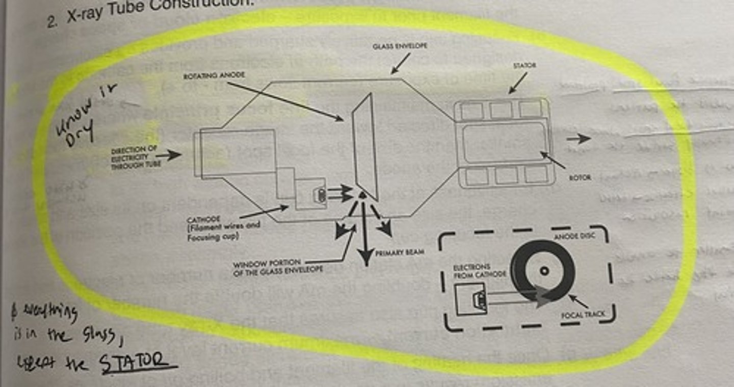
EVERYTHING IS IN THE GLASS ENVELOPE EXCEPT
THE STATOR
cathode
-negative electrode
-composed of the filament wires (thoriated tungste) and focusing cup (molybdenum or nickel)
focusing cup
-Negatively charged
-Provides electrostatic field to control the path of electrons from cathode to anode at exposure time (- to +)
-Aids in maintaining line focus principle
Selecting mA determines the number of electrons free around the filament
-Effectiveness depends on size and shape, and the charge, size, shape and position of the filament in the focusing cup
effective focal spot size
projected toward the patient
actual focal spot size
where electrons actually strike the target
line focus principle
-the size of the focal spot directed toward the image receptor (the effective focal spot) is smaller than the size of the focal spot (actual focal spot) measured on the surfuce of the annode
what is bigger the actual or effective focal spot
actual
smaller effective focal spot
better spatial resolution
the smaller the annode angle
smaller the effective focal spot-> better spatial resolution
induction motor
-stator wiindings and rotor
-operates the rotor that spins and and the anode during a radiogrpahic exposure
-engaging the rotor swithc fires the stator in a circular direction around the x-rau tube resulting in a circular movement of the rotor within the tube
x-ray beam
* xrays are produced isotropically, which means they are produced with equal intensity in all directions--> SCP
leakeage radiation
-radiation that is emitted through the metal protective housing
-should not exceed 1mGy/hr at 1 meter
Principles of Automatic Exposure Control (AEC)
a) AEC units are designed to reproduce a desired amount of receptor exposure on images taken of selected body parts regardless of changes within the patients being examined
The importance of the AEC is
- radiographs taken on mixed population will fall within an acceptable or diagnostic range
- Images WILL NOT necessarily be identical to another
-images will vary due to changes in subject contrast within the patient population
AEC is designed to
reduced the number of repeated radiographs taken on a mixed populatiion of patients due to over and under exposure
AEC places a premium on
effective & accurate positioning & phototimer cell selection
biggest disadvantage of using the AEC
innadequate positiong and phot timer cell collection