Reactance, Impendance and Filter circuits
 Call Kai
 Learn
Learn Practice Test
 Spaced Repetition
 Match
Match Flashcards
 Knowt Play
1/22

There's no tags or description
Looks like no tags are added yet.
Name | Mastery | Learn | Test | Matching | Spaced | Call with Kai | Chat |
|---|
No analytics yet
Send a link to your students to track their progress
23 Terms
Steady State vs Transient
steady state is where voltage and current in circuit settle down to state which lasts forever
if system is suddenly connected to a battery such as closing switch, then system will take time to adapt to the sudden change, this is transient state
transient response
switch from off to on - closing a switch doesnt cause value to instantly jump to final
step response
step function (low voltage to high voltage), known as step response
initial and final values
RC or CRs are first order systems as their behaviours are determined by first order differential equations.
generalise first-order system transient responses in terms of 2 exponentials
exponentials for initial and final values
v = vf + (vi - vf) x e^(-t/tau), same for e. first tirm is steady-state and second term is transient
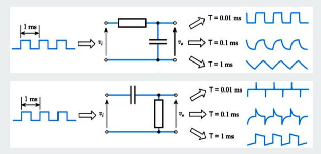
impact of time constant on pulse responses
as tau increases, step response becomes more wavy
RL circuit
resistor-inductor, coil of wire
what does time constant control
how fast circuit settles in transient response
sine waves and phase
described by amplitude, frequency and phase
voltage: sinusoidal
current: sinusoidal but leads the voltage by 90 degrees
phase shift is the reason capacitor analysis is awkward with ordinary resistance
reactance of a capacitor
V/I size depends on the frequency in a capacitor. This is called reactance
reactance (X) (capacitor) = 1/(frequency x capacitance
so reactance is inversely proportional to frequency
so capacitor blocks slow signals more than fast ones
impedance
current and voltage in a capacitor are not in phase
we must use impedance instead of plain resistance
impedance lets us use complex numbers
Impedance formula
Z = 1/frequency x complex number x capacitance
power in capacitor
resistor dissipates energy as heat
so power always positive
capacitor stores energy and gives it back later
so instantaneous power goes pos and neg over a cycle
zero power dissipation
capacitors react to energy instead of wasting
frequency response
feeding a circuit with a sine wave
output amplitude changes with frequency
this is called the frequency response
transfer function
output-to-input ratio, written H(jw).
magnitude response: how much output gets amplified or reduced
phase response: how much output is shifted
bode plot
graphs of gain and phase versus frequency
dB
decibels, gain is written in decibels
dB straight line approximation
20log(Vout/Vin)
corner frequency
where behaviour changes
RC circuit corner angular frequency and frequency
angular: 1/RC, frequency: 1/(2 pi RC)
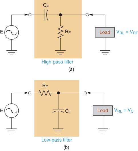
low-pass filter vs high pass
RC can act as…
low:
lets low frequencies through
attenuates high frequencies
capacitor connected to ground
high:
resistor connected to ground
CR circuit
circuit blocks low frequencies and lets high ones through
very low frequencies: output is near zero
-20 decibels per decade
when frequency increases by factor of 10, gain drops by 20 decibels each time
voltage gain in decibels
20log10(Vo/Vi), positive is amplification and negative is attenuation