Navigation ABC
1/45
There's no tags or description
Looks like no tags are added yet.
Name | Mastery | Learn | Test | Matching | Spaced |
|---|
No study sessions yet.
46 Terms
Navigation
process of planning, monitoring, and controlling the movement of aircraft from one place to another
Types of Navigation
3 types;
Pilotage
DED Reckoning
Radio Aids
Pilotage
Depending solely on the pilot,
flying from point to point using landmarks,
visually identified from the cockpit
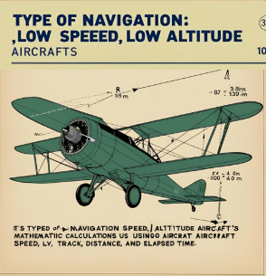
Deductive (DED) Reckoning
Used in low alltitude, Slow speed aircrafts, by Mathematical Calculations based on: Speed, Distance,Track, Elapse Time.

Radio Aids
Advanced type of navigation
Based on sending & receiving signals From Ground Equipment To aircraft’s Embedded Receivers. as;
1.VOR
2.DME
3.NDB
4.RMI
4.ILS
VOR
Very high frequency Omni-directional Range
operating in 108-118 MHZ frequency band.
Ground-based facility Providing 360 radials
Rely on “line of sight” transmiting a two-phase directional signal
Line of Sight in VOR
Line between Neutral Eye Height
and a line Tangent to plane’s nose
in VOR concept; straight line between
Transmitter and Receiver.
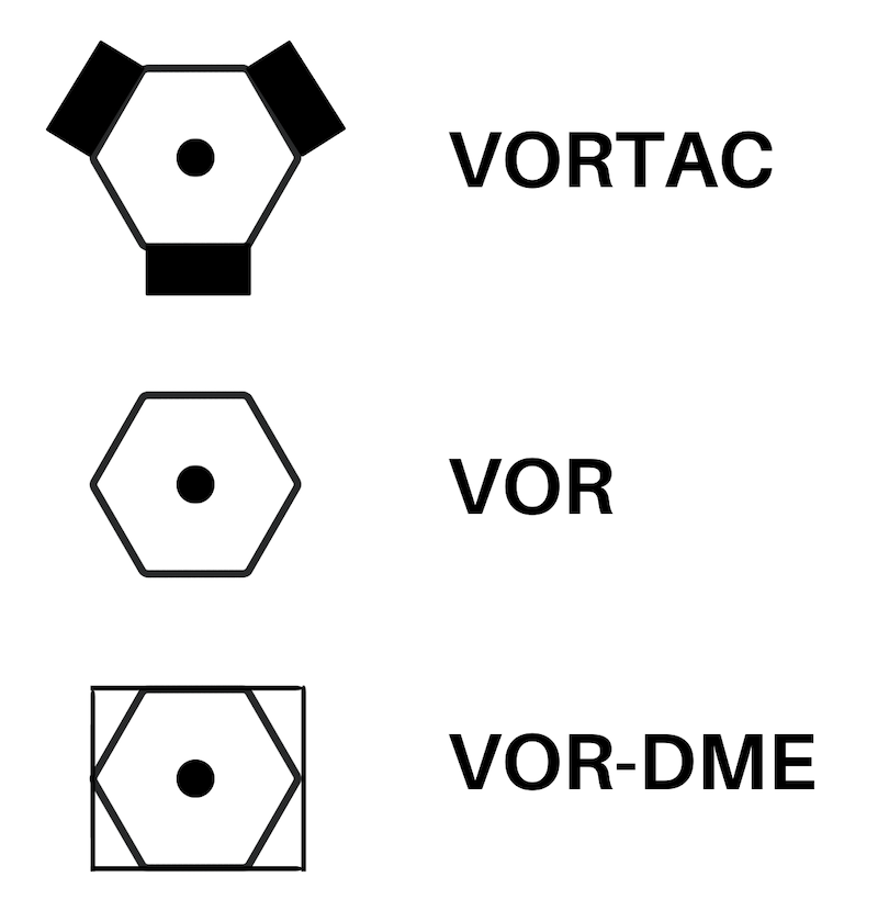
VOR Types
VOR
VOR\DME
VORTAC or TACAN
‘Tactical Air Navigation system’

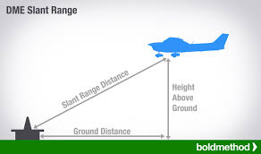
DME
Distance Measuring Equipment of the Aircraft to the Station that
Measures Ground Speed, Distance & Time
by Sending and Receiving Pulses
Limitations:
measuring only Slant range between them.
which is Slightly Higher than the Actual horizontal distance.
Resulting in inaccuracy in speed and time readings when airplane is flying in any other direction than to or from the station.
When flying over the station. it reads distance based on the airplane height in nautical miles
1NM
= 6,080 Feet
MORIS Code
Pilots are required to understand this and be able to identify aircraft call signs as NDB's and VOR's
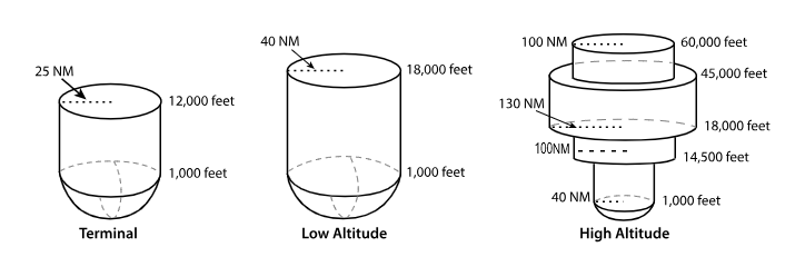
VOR Volumes
T ‘Terminal’
L ‘Low Altitude’
H ‘High Altitude’


T ‘terminal’ VOR
From 1,000 feet AGL
to 12,000 feet AGL
at radial Distances out to 25 NM.


L ‘low altitude’ VOR
From 1,000 feet AGL to 18,000 feet AGL at radial distances out to 40 NM.


H ‘high altitude’ VOR
From 1,000 feet AGL to 14,500 feet AGL at radial distances out to 40 NM.
From 14,500 feet AGL to 18,000 feet at radial distances out to 100 NM.
From 18,000 feet AGL to 45,000 feet AGL at radial distances out to 130 NM.
From 45,000 feet AGL to 60,000 feet at radial distances out to 100 NM.

MRA
Minimum reception altitude at which a waypoint can be identified using two VOR.
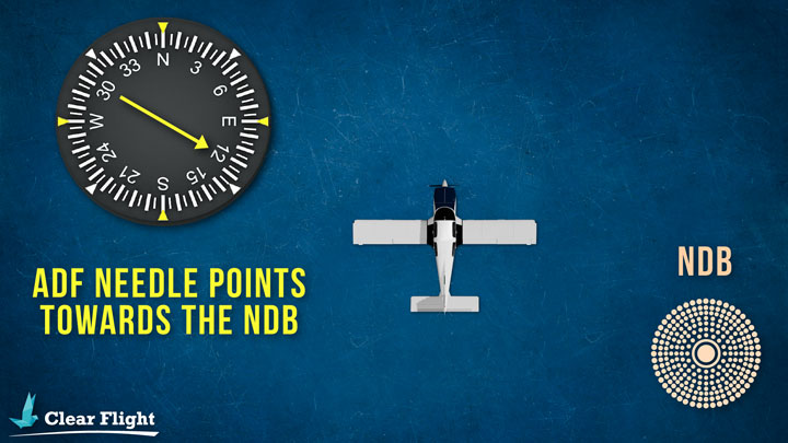
NDB
Non Directional Beacon is an
Economic ground Low Frequency radio transmitter
received by the aircraft’s onboard
Auto Direction Finder ‘ADF’equipment
with its radials propagating around any obstacle to reach its receivers.
CONS; not accurate at;
Night
Shoreline
Bank

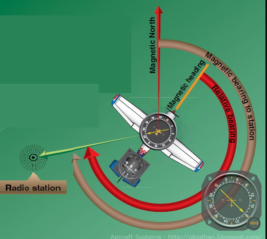
RMI
Radfio Magnetic Indicator.
simplify flying NDB approaches by eliminating the need to add magnetic heading calculations
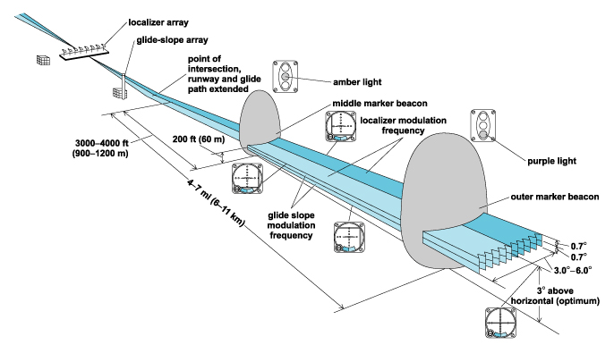
ILS
Primary system for instrumental approaches nowadays
Providing horizontal & vertical guidance.
Consisting of 2 ground equipments;
Localizer
Glide slope
along with distance-measuring equipment

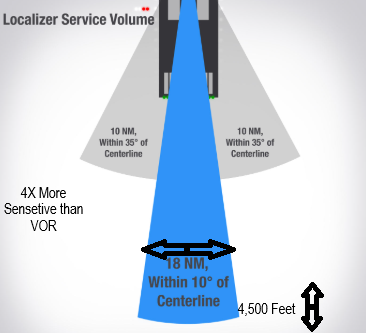
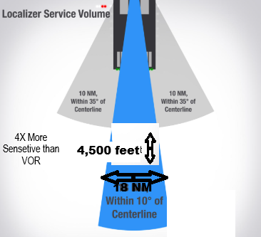
Localizer
In the opposite end of the Runway
Received Up to 18NM, & 4,500 feet
4X more Sensitive than VOR.
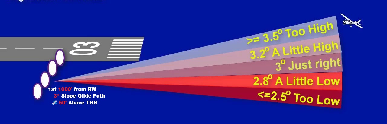
Glide Slope
Ground ‘UHF’ Ultra High Frequency.
in the 1st 1000' from the Runway
Displaced from the Centerline
Insuring 3° slope Glide path &
ensures aircraft is 50ft Above THR
Precision Approach
Provide Lateral and Vertical Guidance
Localizer + Glide Slope
ex. ILS app,
Non-Precision Approach
Provide Lateral Guidnance only,
VOR app,
Localizer app,
NDB app,
RNAV app

ILS Categories
CAT I
CAT II
CAT III; A, B, C
Based on; Visibility, Decision height, & RVR
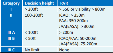

CAT I
(DH>200ft)
Decision Height Not Less Than 200 feet
(RVR>550m)
RVR Not Less Than 550 meter
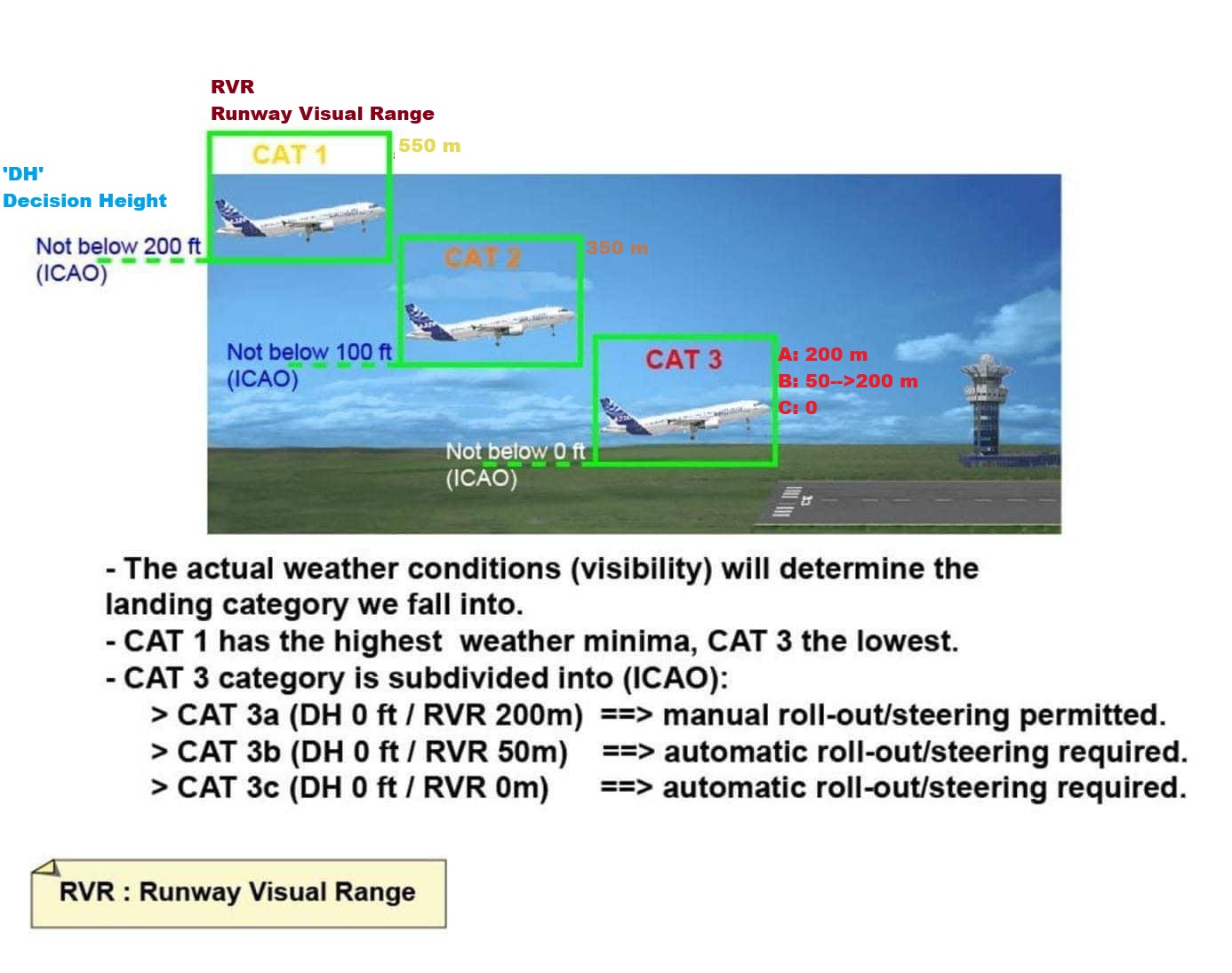

CAT II
-(100>DH>200ft)
Decision Height Less than 100 But Not Less than 200 feet
-(RVR>300m)
RVR Not Less Than 300 meter
Company’s Policy
PF & PM Validated for CAT2 approach on license.
CAT2 Equipped & Approved Aircraft & Runway.


CAT III
3 Types: Alpha, Bravo, Charlie
No Decision
No RVR

RNAV
AREA Modern Navigation System
Allowing aircraft to fly directly to the waypoint without passing over
Ground Equipment.

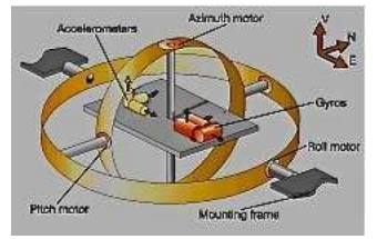
INS
One of the initial systems Enabiling RNAV.
Inertial Navigation System, Self Contained
Detecting plane’s motion and
Indicates its displacement by using
Accelometer to know Speed
Gyroscope to know heading
INS updates position from the last known location.
small errors accumulate over time due to speed/time miscalculations
Corrected by IRS
IRS
The Inertial Reference System
laser gyros reduced the noise
results in overall reduction of integration drift
Having its own database saving the aircraft Motion and Comparing it to the Initial position not using the last position.
RNP
Required Navigation Performance
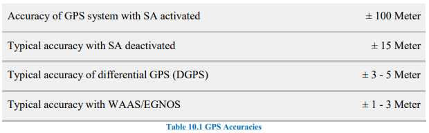
GPS
Global Positioning System:
Part of the Global Navigation Satellite System (GNSS).
used to be 24 now, 33 satellites in orbit, operating in 6 orbital planes.
Requires
2D position uses 3 satellites
3D position uses 4+( +altitude).
Accuracy affected by signal delays due ionosphere/troposphere.
Enhancements:
SA (Selective Availability): Removed to improve accuracy.
DGPS (Differential GPS): Uses ground stations for ±5m accuracy.


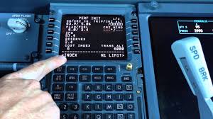
FMC
💘 of flight manegment system providing
Centralize Control for
Navigation and Preformance managment
FLP is Loaded on it before flight calculating;
Air & Aircraft’s Position
Fuel Consumption & ETA
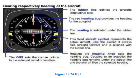
HSI
Horizontal Situation Indicator
Reduce Pilot’s Monitoring Workload by Combining;
Heading, VOR, ADF, ILS, Indicators together in one Panel


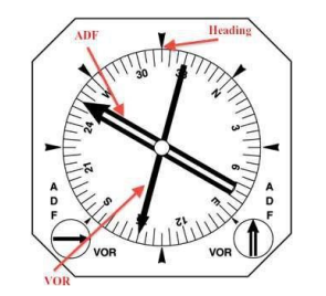
RMI
Displays two VORs or two ADFs or a combination of both, along with Heading.
Climb Gradient Calculations
Rate of Climb =
(Gradient in Ft./nm × Ground Speed) ÷ 60
Rate of Climb =
Gradient in % × Ground Speed
Descent Calculations
The required distance to run =
(altitude ÷1000 × 3)+10
For every 3 knots Headwind -1 nm
For every 3 knots Tailwind +1nm
Leading Radial
where craft starts its turn to
Intercept its intended course
the Heavier & Faster the craft is
the Earlier it will start Turning.
3 Approaches
LDA, MLS and SDF, APPROACHES
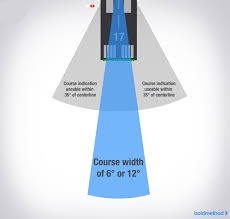
(SDF) Simplified Directional Facility
Providing final approach course similar to an ILS localizer.
Course width is at 6° or 12° for optimal approach quality
may not align with the runway & less precise than an ILS.
Usable indications are within 35° of the course centerline.
Indications beyond 35° are uncontrolled and should be ignored.
The antenna may be offset, with a convergence angle ≤3°written in approach chart.
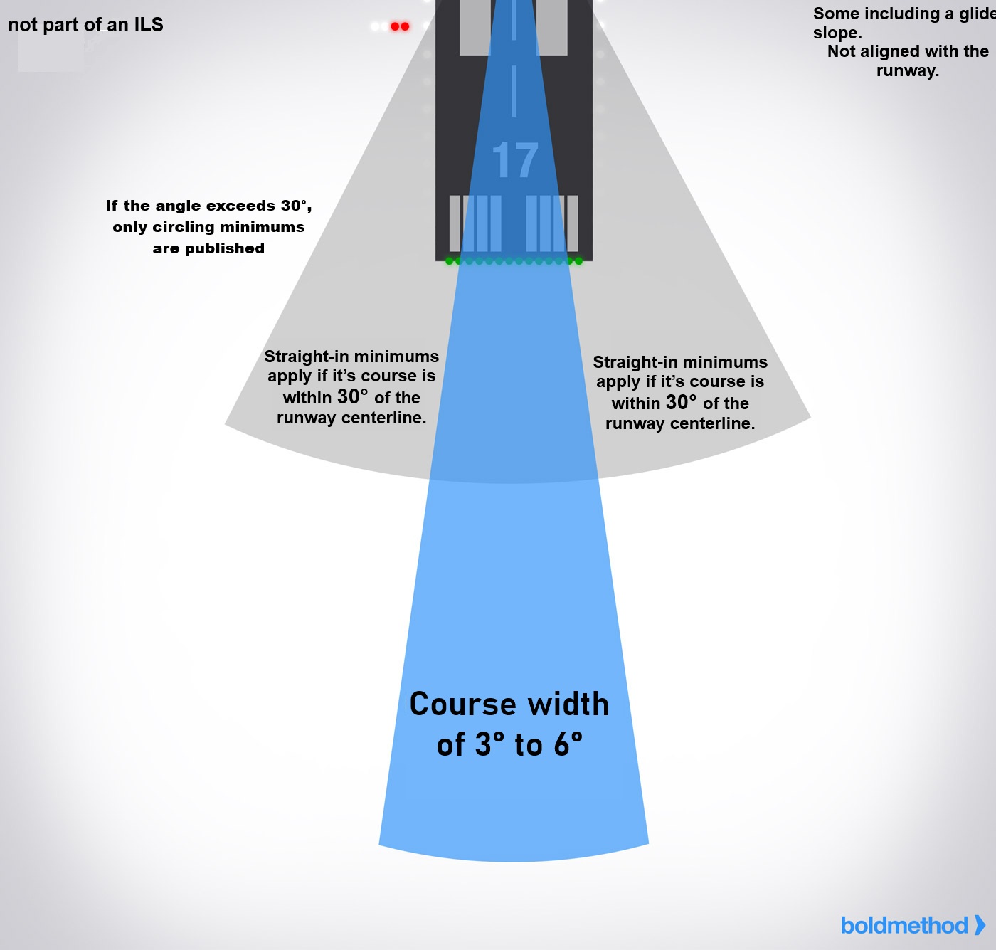
(LDA) Localizer Type Directional AID
Similar in accuracy to a localizer but not part of an ILS.
Course width is 3° to 6°, more precise than SDF.
include Glide Slope.
Not aligned with RWY.
Straight-in minimums applyif course within 30°
of RWY Centerline.
If the angle exceeds 30°, only Circling minimums are published.
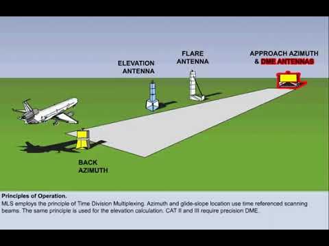
(MLS) Microwave Landing System
provides Precision approach guidance.
It offers, elevation (glide slope), and range information.
Guidance is displayed on CDI or multifunction cockpit displays.
Requires specialized airborne equipment not commonly found in general aviation.
Includes data communication for system status, weather, and runway information.

VASI
Visual Approach Slope Indicator (VASI) provides visual descent guidance using two wing bars (upwind & downwind).
On slope: Upwind bar red, downwind bar white.
Too high: Both bars white.
Too low: Both bars red.
Some airports have three-bar VASI for large aircraft.
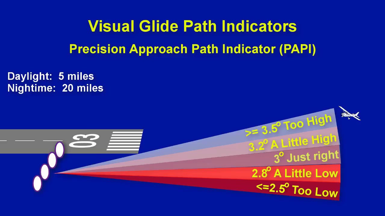
PAPI
Precision Approach Path Indicator (PAPI) provides visual descent guidance like VASI.
Uses a single row of lights, usually on the left side of the runway.
TRI-color
Tri-Color System provides visual approach guidance using a single light unit.
Red indicates below the glide path.
Green indicates on the glide path.
Amber indicates above the glide path.
A dark amber zone exists below the glide path but should not be mistaken for an "above" indication.
Pulsating Visual Approach Slope Indicator
uses a single light unit for visual guidance.
On glide path: Steady white light.
Slightly below glide path: Steady red light.
Further below glide path: Pulsating red light.
Above glide path: Pulsating white light.
Pulsating rate increases as the aircraft moves further above or below the glide slope.
4o mini