Digital imaging ch. 22/23/24
1/82
There's no tags or description
Looks like no tags are added yet.
Name | Mastery | Learn | Test | Matching | Spaced |
|---|
No study sessions yet.
83 Terms
FLAT-PANEL DETECTOR EVOLUTION
Referred to as Digital Radiography (DR)
Introduced in 1995
Manufacturers striving to improve quality and functionality
Flat panel detector is commonly used term
• “panel”
Direct detector configuration
Use a photoconductor (convert x-ray photons into an electronic signal)
indirect detector configuration
Uses scintillator (converts incoming x-ray photons to light)
direct vs indirect conversion diagram
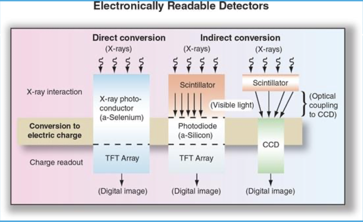
INDIRECT DETECTORS (TWO STEP PROCESS)
1. Use a scintillator to convert x-ray photons to light first
2. Light energy converted to electronic signal
Electronic signal collected by two possible methods
• Thin Film Transistor (TFT)
• Charge-Coupled device (CCD)
INDIRECT DETECTORS
Amorphous silicon requires a scintillator
Scintillation material of two possible types
• Cesium iodide (CsI)
• Gadolinium oxysulfide (Gd2O2S)
Isotropic light emission
layers of digital detector
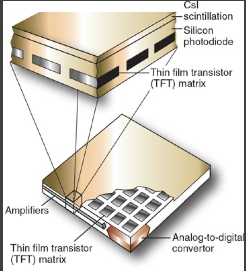
ELECTRONIC SIGNAL CAPTURE
Employs any of three (3) technologies
• Thin film transistor (TFT)
• Charge-coupled device (CCD)
• Complimentary metal oxide semiconductor (CMOS) (not used)
Designed to convert light energy into electrical signal
• Transmission along detector circuit pathways
• Analog-to-digital convertor (ADC)
what does TFT stand for
THIN FILM TRANSISTORS
THIN FILM TRANSISTORS (TFT)
• Used in both indirect and direct detectors for Electronic readout of signal
• Collected as an array or matrix of pixel-size detector elements (DEL’s)
• Pixel size directly related to DEL size
• Readout is pixel-by-pixel and column by column basis
TFT FILL FACTOR
• Fill factor is determined by percentage of DEL consisting of sensing material
80 % fill factor then 20% covered by electronics.
• Fill factor affects image quality
Higher fill factor = higher (better) spatial and contrast resolution (absorbing more photons)
higher fill factor=more pixels waiting for signal
what does CCD stand for
CHARGE-COUPLED DEVICE
CHARGE-COUPLED DEVICE (CCD)
• CCD is a photodetector (gathers signal)
• Released line by line to the ADC (gets send to here after 1st step)
• Electronic signal then sent to computer for processing
what does CMOS stand for
COMPLEMENTARY METAL OXIDE SEMICONDUCTOR
COMPLEMENTARY METAL OXIDE SEMICONDUCTOR (CMOS)
• Similar to a CCD, attached to scintillator material
• CMOS sensors are more susceptible to noise when compared to CCD
• Light sensitivity tends to be lower.
not used anymore
DIRECT DETECTORS
• Use amorphous selenium (a-Se) as photoconductor
• No scintillating layer
• Direct action of x-ray photons converted to electronic signal in a-Se layer
• Charges collected by TFT for readout
best DQE (sensitivity to radiation)
IMAGE ACQUISITION, PROCESSING, AND DISPLAY
• Regardless of conversion type, result is a latent image that needs to be read out.
• Readout completed in a logical sequence
• One difference only exposed elements are used for image (only area that is gathering photons, that we collimate to, gets processed and shows up on the image)
• Image processing similar to CR processing
• DR panels capable of pre-processing and post-processing
Pre-processing permits DEL calibrations
- Image Display is the final step just like CR
Portable detectors
• Wireless
• Or Hard-wired with tether cable
Integral detectors
• Typically, hard-wired to radiographic equipment
ex. wall Bucky
AUTO-DETECTION TECHNOLOGY
DR panels typically require a communication with x-ray generator (need to select correct detector, need to activate it)
Interface is vendor-specific
• Can be expensive
• Limits versatility of panel usage in various rooms
Newer DR panels eliminate the traditional generator interface
• Employ new “auto-detection” technology
• Commonly referred to as “trigger panels”
Panels are wireless
No true generator interface (not plugged in)
TFT is charged by on-board capacitor prior to exposure (on imaging plate)
Presence of x-radiation hitting panel “triggers” TFT to collect signal
Exposure terminated by manual timing or automatic exposure control (AEC) (machine stops once it gets proper EI number)
Data read-out completed; panel recharges for next exposure
DR PANEL PRECAUTIONS
Respect the level of sophistication a DR panel represents
• Far more than a cell phone
Damaged panels sent to manufacturer for analysis
• DR panel “autopsy”
Fluid Invasion
• Encase in protective bags
Weight load restrictions and bending
• Standing feet, portable exams on obese patients, etc
Avoid panel dropping
• Drop protection insurance
Clean panels according to manufacturer recommendations
Newer panels have less weight and improved durability
It is your responsibility to know and understand DR panel restrictions from the manufacturer
Digital Exposure Considerations
•Traditional parameters of radiographic image formation still apply
•SID, OID, SOD, Inverse Square Law
•Focal spot size
•kVp
•mAs
•Higher mA, shorter exposure times
•Tighter Collimation (better image)
•Grids
•Filtration
•Patient size and condition
•Old rules of kVp and contrast do not apply, in the traditional sense
•mAs and image density no longer applicable
•Total amount of exposure to the detector is converted to electronic “SIGNAL”
-machine knows what to use, quits when done
Higher kVp’s now compared to analog imaging
Due to higher k- edge of detector 15% Rule of kVp/mAs
Increase of kVp values reduce entrance skin exposure (ESE) to patient, and lower mAs values
mAs values that are too low introduce quantum mottle (noise)
what does SID stand for
source to image distance
what does OID stand for
object to image distance
what does SOD stand for
source to object distance
15% rule of kVp/mAs
if you want your image to change, you need to increase by 15% kVp or 50% mAs
Exposure Technique Systems
Exposure technique systems as important as ever
Image quality is referenced to an Exposure Indicator #
EI# can vary between manufacturers/rooms
Departments must equip staff with both exposure technique charts and target EI#s
Target EI#s established as a standard of care
Two distinct technique systems
• Fixed-kVp, variable mAs
• Variable kVp, fixed mAs
Fixed kVp system best suited for digital receptors
Fixed kVp System
• Requires an optimum kVp for various body parts
• Ensures desired image contrast
• mAs adjustments based upon the optimum kVp
• mAs changes increments of 30%
• Every 5 cm thickness change requires a 30% change in mAs (increase/decrease)
Variable kVp System
• Requires a threshold kVp
• Typically 30 kVp
• kVp change for each 2-cm change in part thickness
• (2 kVp × part cm) + 30 kVp = new kVp
• 15% Rule applies with this system
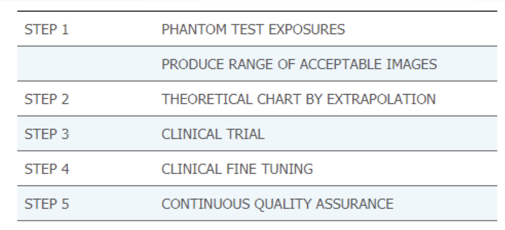
Establishing Technique System
• Done as a Five (5) Step Process
• Test exposures using a phantom Consult QC tech and /or Rad. for acceptability
• Create trial exposure chart using range of large and small sizes
• Place technique chart into clinical trial
• Clinical fine tuning of trial chart exposures, Referencing
clinical images and part measurements
• Re-examine chart for accuracy and continue making adjustments over extended period
• Image acceptability primarily based upon image noise
• EI #s used as a reference point
Exposure Techniques
• Image noise directly related to exposure
• Digital post-processing software more tolerant of over exposure
• Underexposure has less exposure latitude
• Dose Creep! (overexposing still looks ok)
• Technologists should employ “the highest kVp within the optimal range for the position and part, coupled with the lowest amount of mAs as needed to provide an adequate exposure to the image receptor (ASRT 2012 Best Practices In Digital Radiography)
Techniques Systems and ALARA
• ALARA compliance based upon Target Exposure Index (EIT) values
• Target values need to be established by department
• Deviation Index (DI) Values based upon EIT
• EI# and DI# can be displayed as part of DICOM header on images
Deviation Index (DI)
• Created by AAPM
• Establishes a range of EI# variances based upon EIT
• Scale in increments
• +25 on positive side of zero (overexposure) 25% increase is +1
• −25 on negative side of zero (underexposure) 25% underexposed is -1
• DI values +3 or greater considered ALARA violation and cause for concern (75% overexposed)
Exposure Factors and DR Image Quality
Image quality a function of several factors
• Noise, artifacts, resolution, and DQE
Scatter/secondary production primarily a function of mAs, rather than kVp
Underexposure can produce photon starvation
Extreme overexposure can yield data drop due to DEL (detector element) saturation
Assessing DR Image Quality
Look at image in “totality”
• Positioning and relevant anatomy on image
• Quantum Noise or mottle
• Collimation
• Motion distortion
• Resolution
• Brightness/contrast
• Artifacts
Use EI# as frame of reference for exposure to detector
If you are satisfied with the image appearance and the EI# supports the look of the image, feel comfortable in sending image for interpretation
Digital Processing Considerations
• From Analog to Digital re: image density
• Grossly overexposed images can still look good!
• Quantum mottle
• Minimum Exposure Index
Benefits to Digital Processing:
• increased latitude (can see a lot more shades of gray)
• increased margin for error
Electronic Masking
• Post-processing function
• Manual or automatic
• Removes nonclinical data from image file
• Also known as “cropping”
• Intended to eliminate extraneous brightness from image edges
• Reduces veil glare (white around the edges)
• No impact upon image resolution
• NOT a SUBSTITUTE for collimation
• Can impact accuracy of EI# in older CR/DR systems
• Incidental findings on images, important to radiologist
• ASRT Position Statement on Electronic Masking
• “that a digital image should not be cropped or masked such that it eliminates areas of exposure from the image that are presented for interpretation” (ASRT 2015).
Electronic Annotation
• Used to indicate image acquisition conditions
• upright, decubitus, inspiration, expiration, semi-erect, etc.
• ABSOLUTELY not a substitute for lead markers to indicate laterality (Lt versus Rt)
• Convenient “cut and paste” feature
• Valuable for radiologist
• ASRT Position Statement
• As a best practice, the ASRT White Paper recommends “consistently using lead anatomic side markers captured on the original image during the x-ray exposure” (2012).
Tenets of Radiologic Images
Medical radiographs are considered a legal document just as all contents of a patient’s medical record.
A medical image of a patient is a pictorial record of the patient’s anatomy and
medical condition.
A medical image is an image of the patient at a single moment in the patient’s medical timeline.
The accuracy of medical image interpretation is a function of the quality of the image created and includes technological and human components being optimized.
Radiologists expect that department routines and procedures are followed when creating medical radiographs, and any variance explained completely.
Radiologists assume that images are produced in an ALARA-compliant manner.
Diagnostic Yield
important information on the req. Varies between imaging modalities
diagnostic efficacy
how well our images represent the patient
image fidelity
LCR
Low-contrast resolution
LCR and Artifacts
• Due to spectral response of digital detectors
• Wider dynamic range of photon energies detected by receptor
• Yields additional image gray shades that can be very subtle
• Produces artifacts on DR images
• Clothing, hair braids, sheets, transfer devices, positioning aids, skin keloids, etc.
• Unexpected radiographic findings need an explanation to radiologist
Data Drop Artifacts
• Due to DEL saturation and excessive exposure
• Produces misrepresentation of patient information on image
• Several correction methods
• Post-processing and pixel recovery
• Tissue bolusing
• Collimation (not masking)
• Compensating filtration
Digital Artifacts
All image artifacts need to have an explanation and mechanism for removal or elimination
Image “ghosting or phantom image (can still see previous image under new image)
Electronic artifacts
Scratches or tears
Digital
Artifacts
Opaque spots on image (dust)
White lines
Light spots on images
Drop out (pixels drop out)
Backscatter fogging (quantum mottle)
Reticulation
CR transport artifacts
Informatics
• Devices and processes
Platforms
• Particular device to pursue informatics
BMI
Biomedical informatics
• Platforms used for medical purpose applications
PACS
picture archiving and communications system
HIS
Hospital information system
RIS
Radiology information system
EMR
Electronic medical record
EHR
Electronic Health Record
PACS Network
• Separate PACS network allows for large data files to be moved quickly
o LAN uses Ethernet
Bandwidth of 10 megabits per second (Mbps)
o WAN slower
PACS Difficulties
LARGE FILES
LIMITED BANDWIDTH
SPECIAL LANGUAGE
PROBLEMS INTERFACING WITH HIS
HIS Hospital information systems
Database containing all patient medical record information except for radiology
RIS Radiology information systems
Radiology-specific database
Electronic Health Records (EHR)
• Electronic version of an individual patient’s collection of medical documents
• Patient portal
• Seamless stream of patient information that is shared in a secure fashion by healthcare entities
• Integrated with PACS, HIS and RIS in a holistic approach to patient care
• Vendor neutral archive (VNA)
VNA
vendor neutral archive
DICOM
digital imaging and communications in medicine
DICOM Standards
• Originated in 1980sby ACR and National Electrical Manufacturers Association (NEMA)
• Standard format for communicating imaging files around the world
NEMA
National Electrical Manufacturers Association
HIPAA
Health Insurance Portability and Accountability Act
• Medical information must be encrypted
confidentiality
HL-7
• Provides standards of interoperability between stakeholders
IHE
Integrating Healthcare Enterprise
Hardware
Mainframe, central processing unit (CPU), memory, input devices, output devices, BUS
Software
Computer programs, applications, operating systems (OS)
LAN
Local Area Network
WAN
Wide Area Network
Hard-copy image display
Images on film
Laser printers and dry processors
Soft-copy display
Flat screen monitors
Monitor quality greatly affects interpretation
Must be assessed regularly using approved QC methods
•resolution, luminance, contrast, bit depth, uniformity, and glare
CRT
cathode ray tube monitor
LCD
liquid crystal display monitor
LCD Flat Panel Monitors
• Light source shines on individual pixels
• Liquid crystal and hydrogenated amorphous silicon TFT s
Located between glass plates
Data Storage
Image storage requirements are huge
Images typically archived 5–7 years (Pediatric and litigation images indefinitely)
Terabyte storage a typical requirement (1 Tb = 10,000 Gb, 10,000,000 Mb)
Storing and sharing medical images done via cloud computing
Data Compression effectively manages data volumes in radiology (Lossless versus lossy compression)
Short-term storage
• Local hard drive
• PACS server and redundant array of independent discs (RAID)
Long-term storage
• Jukebox of disks or tapes (not used anymore, use cloud)
Workflow and Security
Understanding clinical informatics workflow
Computerized provider order entry (CPOE)
Clinical decision support system (CDSS)
Medical record & image privacy is critical
EHR security must adhere to National guidelines
CPOE
computerized provider order entry
CDSS
clinical decision support system