Electric Circuits Model Answers - Physics (NEW)
1/48
There's no tags or description
Looks like no tags are added yet.
Name | Mastery | Learn | Test | Matching | Spaced | Call with Kai |
|---|
No analytics yet
Send a link to your students to track their progress
49 Terms
Define potential difference.
Potential difference is the energy transferred (or work done) between two points in a circuits, per unit charge (V = W/Q).
Define EMF.
Emf is the work done per unit charge by the power supply or cell, converting energy into electrical potential energy of the charges
Define current.
The rate of flow of charge ( I = ΔQ/Δt ).
Derive the equation linking current, with the number of electrons N, flowing past a point in time Δt with the current I.
• The charge flow ΔQ = Ne, where e is the magnitude of the charge on each electron, e = 1.6 x 10^-19 C. • I = Ne/Δt
Explain how to calculate the number of electrons in a certain amount of charge.
• Number of electrons = total charge/ charge per electron.
• N = Q / 1.6 x 10^-19
Define resistance.
The ratio of p.d. to current ( R = V/I ).
Derive the formula for the ratio of currents, down parallel branches of a circuit.
(Resistance eq in parallel) • The pd across each brance is the same V1 = V2. • V = IR , so • I1 R1 = I2 R2 • So I1 / I2 = R2 / R1 • Or, the ratio of the currents is the reciprocal of the ratio of the resistances. • E.g. If resistor 1 is 100 times greater in resistance than resistor 2, it will receive 100 times less current than resistor 1 (inversely proportional).
Derive the formula for resistors in series.
• Vtotal = V1 + V2 + V3 (due to energy conservation).
• V = IR
• I total R total = I1 R1 + I2 R2 + I3 R3
• IRtotal = IR1 + IR2 + IR3
• Rtotal = R1 + R2 + R3
Derive the formula for resistors in parallel.
• I total = I1+ I2 + I3 (due to charge conservation). • I = V/R • Vtotal / Rtotal = V1/R1 + V2/R2 + V3/R3 • V total = V1 = V2 = V3 = V (due to energy conservation) • V/Rtotal = V/R1 + V/R2 + V/R3 • 1/Rtotal = 1/R1 + 1/R2 + 1/R3
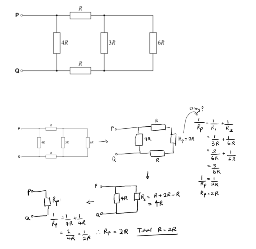
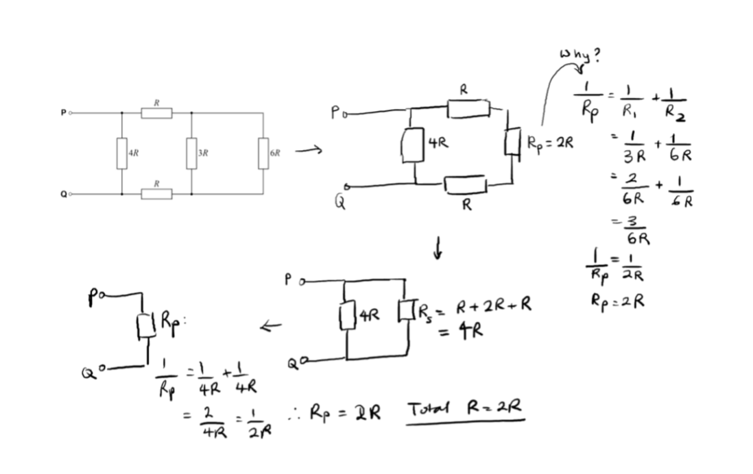
Calculate the effective resistance between P and Q (see diagram).
Answer : Total R = 2R
State Kirchoff's potential difference law (KVL).
• The sum of the potential difference drops, is equal to the sum of the emfs around a closed loop, within a circuit.
• This is due to conservation of energy.
State Kirchoff's current law (KCL).
• The sum of the currents into a junction, is equal to the sum of the currents out of the junction. • This is due to conservation of charge.
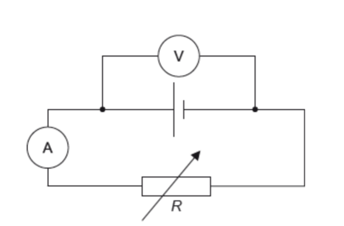
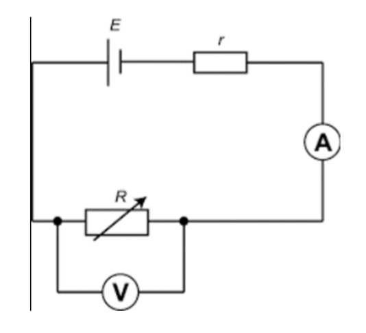
A student wants to determine the resistance of the resistor shown in the circuit below (see diagram). Student A claims that both the voltmeter and ammeter should be 'ideal' in order for an accurate measurement using this circuit. Student B saya that it is only the ammeter that needs to be 'ideal'. Explain who is correct.
• To determine the resistance of the resistor, the student would use R = V/I, where V is the pd across the resistor and I is the current through the resistor.
• An ideal ammeter has zero resistance. • If the ammeter had non-zero resistance, then there would be a pd across the ammeter. •Therefore, the pd measured by the voltmeter would be the sum of the pd across the ammeter and the resistor. This would be problematic as the resistance calculation requires only the pd across the resistor (the voltmeter position would have to change to be only around the resistor).
• An ideal voltmeter has infinite resistance. • If the voltmeter had non-infinite resistance, then it would draw some current, and reduce the total resistance of the circuit, increasing the overall current. • However, this would not affect the resistance determination, as the ammeter would still be measuring a genuine current through the resistor. • So student B is correct.
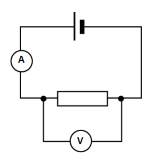
A student wants to determine the resistance of the resistor shown in the circuit below (see diagram). Student A claims that both the voltmeter and ammeter should be 'ideal' in order for an accurate measurement using this circuit. Student B says that it is only the voltmeter that needs to be 'ideal'. Explain who is correct.
• To determine the resistance of the resistor, the student would use R = V/I, where V is the pd across the resistor and I is the current through the resistor.
• An ideal voltmeter has infinite resistance.
• If the voltmeter had non-infinite resistance, then it would draw some current, (increase the total current in the circuit as total resistance of the circuit decreases).
• This would mean that the ammeter reading would give the sum of the current through the resistor and the current through the voltmeter.
• Meaning the resistance calculation would not be possible as this should only use the current through the resistor, which is not measured here.
• If the ammeter has non-zero resistance, then the total resistance of the circuit would increase and there would be pd across the ammeter.
• Neither of those consequences are problematic thoughm as the voltmeter still only reads the pd across the resistor, and the current reading is still the same current passing through the resistor.
• So the ammeter can have a non-zero resistance and student B is correct.
Define lost volts.
The energy per unit charge, transferred to the internal resistance of a cell (= Ir).
Define terminal potential difference.
Terminal pd, V = EMF - Ir (where r is the internal resistance of the cell and I is the current through the cell).
Explain why connecting an ideal voltmeter directly around a cell allows us to measure the emf directly.
• The ideal voltmeter has infinite resistance. • So the current is approx. zero • V = Emf - Ir • The lost volts is zero • And terminal pd is equal to EMF
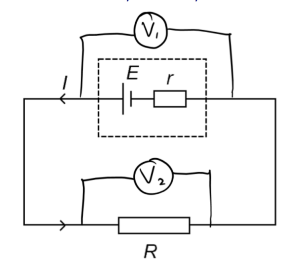
A teacher connects a circuit as shown. Student A says the reading on each voltmeter should be the same (One voltmeter connected parallel to the cell with internal resistor, and another voltmeter in parallel to the resistor along the circuit). Student B says that they should be different. Explain who is correct.
• Student A is correct
• Because we assume the wires to have zero resistance
• Therefore, there is no pd dropped across the wires • So, as the sum of the EMF is equal to the sum of pd drops
• Both voltmeters read the terminal pd, V = EMF - Ir
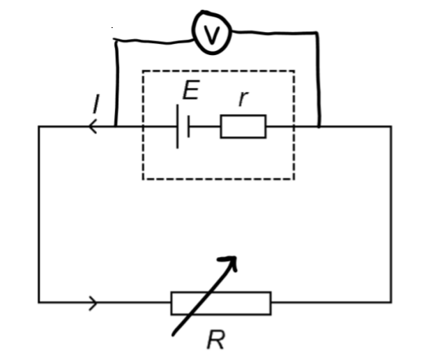
A student connects a circuit as shown (Voltmeter in parallel to the cell with internal resistor, and along the ciruit is a variable resistor). Explain what happens to the reading on the voltmeter as the resistance of the variable resistor is decreased.
• The voltmeter reads the terminal pd, V
• V = EMF - Ir
• As the resistance of the variable resistor is decreased, the total resistance in the circuit decreases.
• Measning the current, I = EMF/Rtotal will increase.
• So the lost volts, Ir will increase
• And as the EMF is fixed
• Terminal pd will decrease
Explain why a battery will get hot when the current passing through it is high.
• If the current is high, the lost volts, Ir will be high.
• So there will be a large amount of energy per unit charge, transferred to the internal resistance of the cell.
• This energy is transferred to the resistor ions.
• Causing them to vibrate with higher amplitudes, increasing the temperature.
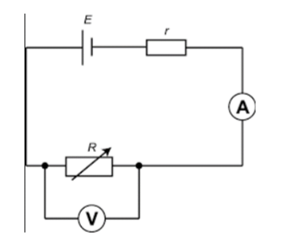
Draw a ciruit diagram required to determine the EMF and internal resistance of a cell.
A circuit with a cell and internal resistor, along the circuit is a variable resistor with a voltmeter in parallel to it, and then further along is an ammeter. (See diagram).
Describe how to perform an experiment to determine the EMF and internal resistance of a cell.
• Set up a series circuit with an ammeter in series with a variable resistor and cell.
• A voltmeter should be connected across the load resistor - this will measure terminal pd (this is identical to connecting the voltmeter across the cell).
• Measure current using ammeter.
• Change the current by changing the resistance of the variable resistor and measure the current and pd again for a range of currents.
• Plot current on x axis, terminal pd on y axis.
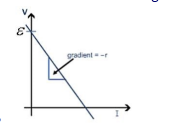
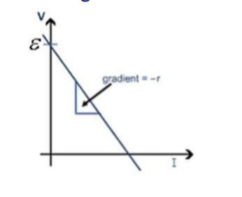
• V = -r I + EMF • y = mx+c • Gradient of line of best fit = -r, y intercept = EMF
• To determine the internal resistance, multiply the gradient by -1.
Explain the significant of the x and y intercepts of this graph. (Plot a graph of V against I, with EMF as the y intercept and m=-r (the graph is of negative gradient).
• The x intercept is when the terminal pd is zero. • This means that all of the EMF is being transferred to the internal resistance of the cell as 'lost volts'. (V = EMF = Ir) • No energy is being transferred to the load resistance and the current cannot continue to increase.
• The y intercept is when the EMF is equal to the terminal pd. • This is when the current is zero and therefore no energy is being transferred to the internal resistor. • Lost volts, Ir = 0.
Define Power
• The rate of transfer of energy (P = E/t)
Derive the other 2 power equations from P = VI
P = VI and V=IR
Substitute V=IR into P=VI
P= IR x I = I²R
I = V/R
Substitute that into P = VI
P = V x V/R
P = V²/R
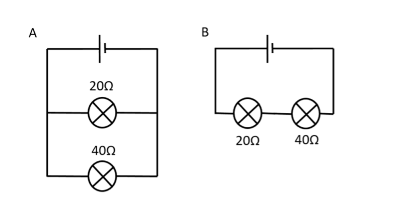
Explain which bulb is brighter in each case.
In circuit A, the pd. V, acrosseach bulb is the same.
Therefore, as P = V²/R , the bulb with the lower resistance wil have a higher power.
So the 20Ω bulb is brighter in circuit A.
In circuit B, the current, I, through each bulb is the same.
Therefore, as P = I² R. the bublb with the higher resistance will have a higher power.
So the 40Ω bublb is brighter in circuit B.
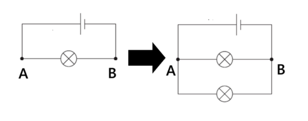
i) How does the potential difference across A and B before an extra light bulb is connected compare with that after an extra light bulb is connected (in parallel to the cell with internal resistance and the first light bulb)?
• When the extra light bulb is connected in parallel, the total resistance of the circuit decreases.
• This means that the total current in the circuit increases, as I total = EMF/ R total, and EMF is fixed.
• So the lost volts, Ir, increases (as current increases).
• This means the terminal pd across AB decreases, as V terminal = EMF - Ir.
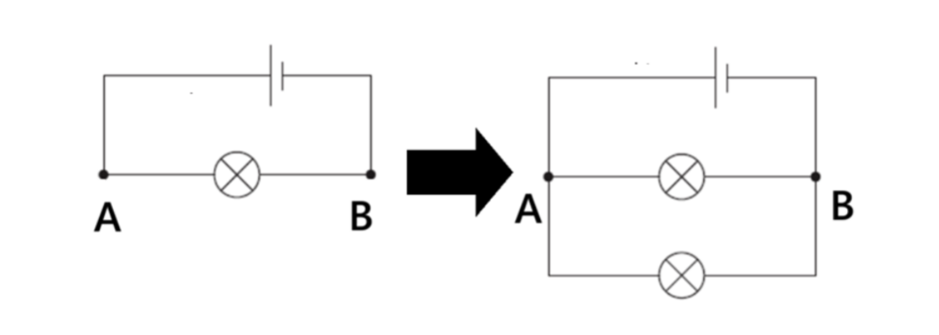
ii) What can we say about the brightness of each light bulb after an extra light bulb is connected to the curcuit (assuming the brightness of the bulb increases with the energy transferred)?
• The power across AB is given by P = V^2/R, where V is the pd across AB and R is the resistance of the bulb between A and B.
• As the terminal pd decreases as extra bulbs are added (because lost volts increase due to the increase in current, caused by the decrease in total resistance), the power across AB will decrease.
• And therefore the brightness will decrease, as extra bulbs are added.
Name and define each of the terms in the equation I=nqvA
I is current - rate of flow of charge
n is the number density of free charge carriers - the number of charge carriers per unit volume ( n = N/V )
q is the charge on an electron = 1.6 × 10^-19 C
v is the drift velocity of electrons - the mean speed of electrons due to an applied pd.
A is the cross sectional area of the material carrying current
Derive I=nqvA
There are N electrons with a drift velocity, v, along a wire of length, x , and a cross sectional area, A
The current I = ∆Q/∆t
∆Q is total charge flowing through a point in a time ∆t
∆Q = Nq, where q is the charge on the electron
v = x/ ∆t
Substuting this into I = ∆Q/∆t
I = ∆Q/∆t = Nqv /x
There is a number density, n, of electrons, n=N/V, so N = Vn = Axn (Volume= area x length x number of electrons)
Substituting back into I = Nqv /x
I = Anqvx /x
I = nqvA (x cancels out)
Draw a diagram of a circuit you could use to determine the resistance of a wire.
Note: Only the second diagram allows you to change the readings, by adding a variable resisitor, which changes its resistance, so current changes and the corresponding values of the pd can be found with a plotted graph.
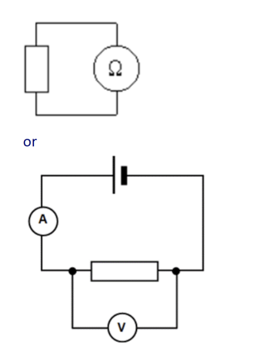
Explain how to determine the resistance of a component from V, I graph.
Choose a point on the IV graph and identify the current and pd values.
R = V/I
(Note: this is not the gradient)
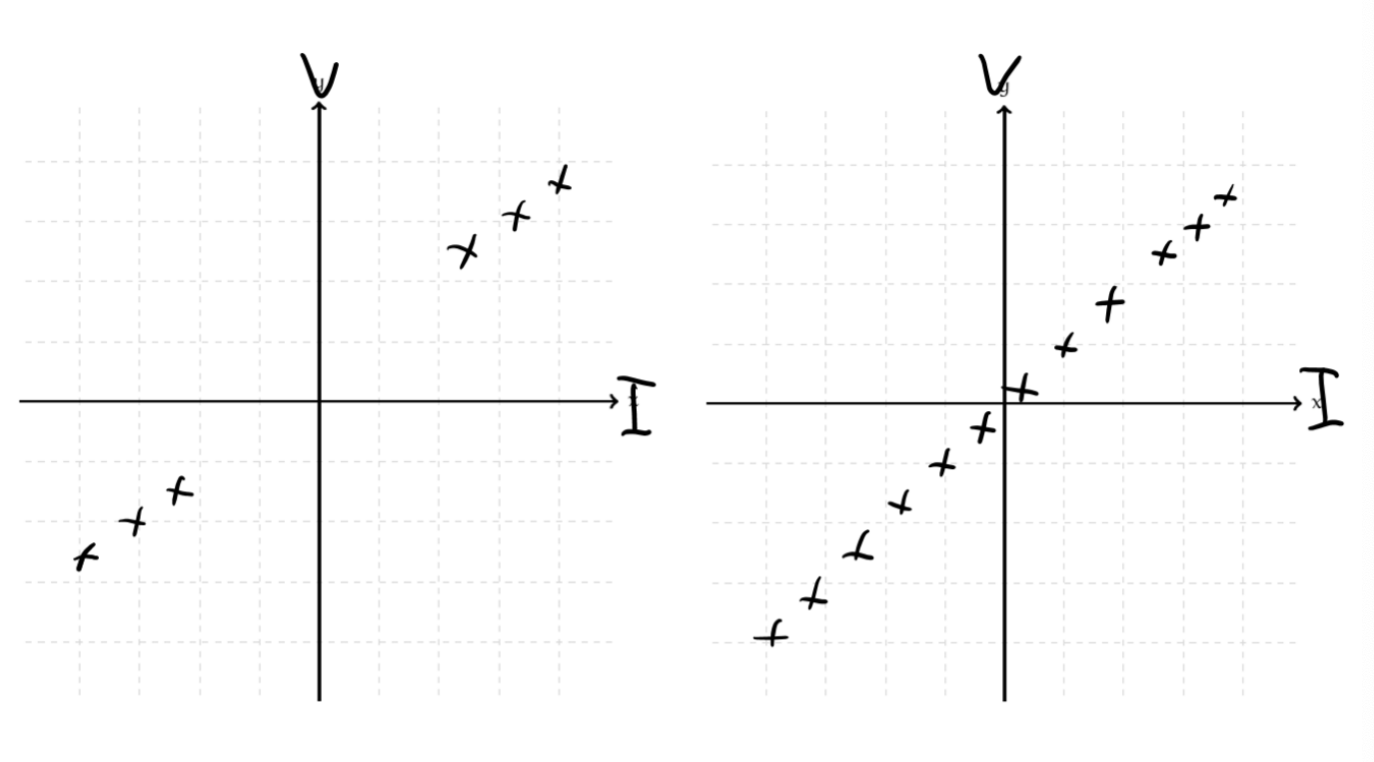
Draw the IV graphs and the VI graphs for an ohmic conductor of high resistance (a), and an ohmic conductor of a low resistance (b), a filament lamp, a termistor, and a diode.
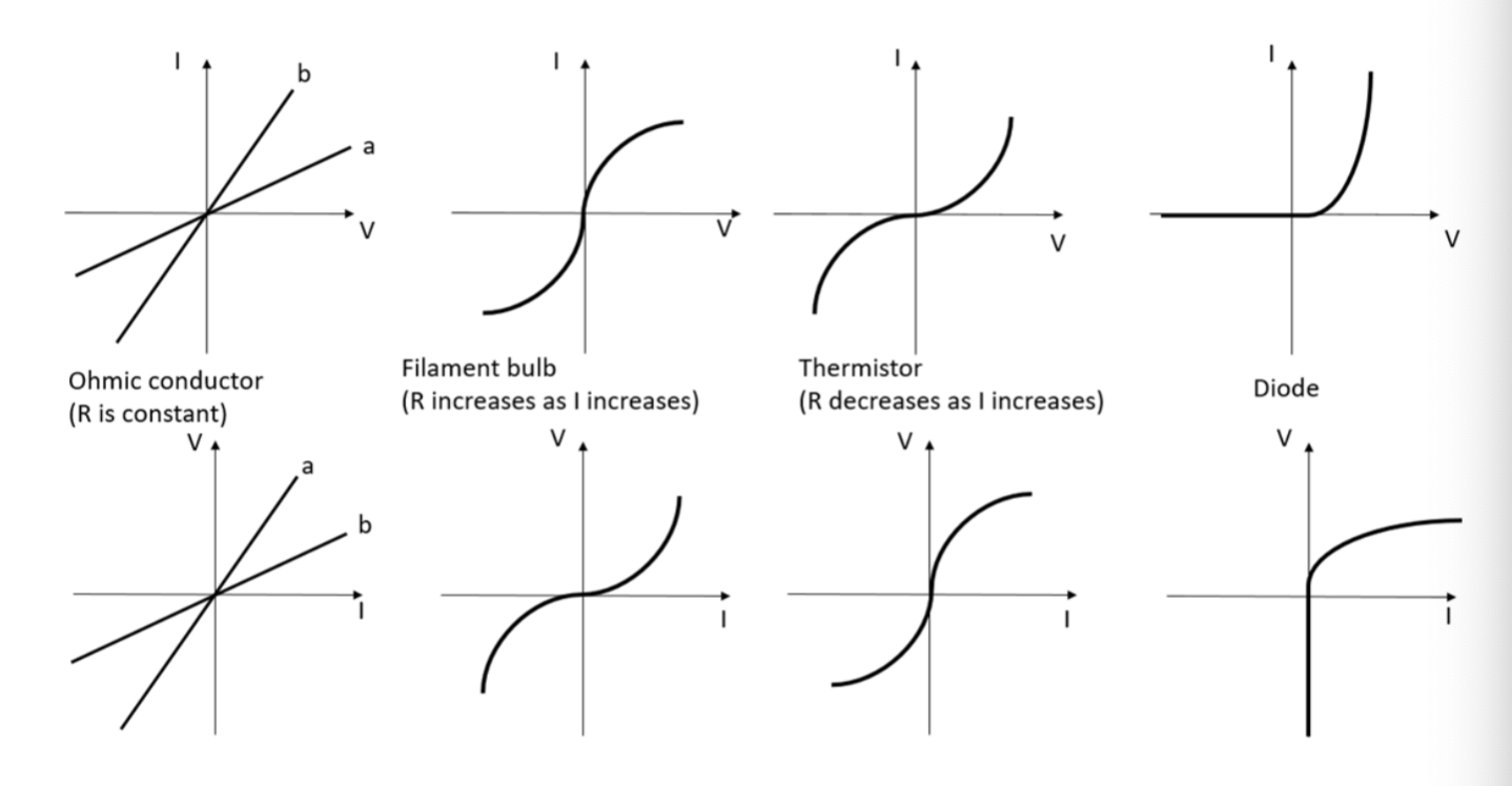
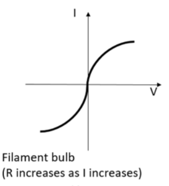
Explain the IV relationship for a filament bulb. [5]
(Talk about drift velocity)
As current increases, the electrons collide more frequently with lattice resistor ions, transferring more energy to them per second OR as pd increases, electrons gain more energy and transfer more energy to the lattice resistor ions.
This causes the reisitor ions to oscillate with greater amplitudes, so the temperature of the resistor increases.
This causes ore frequent collisions between the electrons and the lattice ions, limiting the drift velocity.
This cuases the current, I=nAvq to increase by a smaller factor than the potential difference (as n, A, q all fixed).
So, as resistance is the ratio of pd to current, if pd increases by a greater factor than current does, the ratio R=V/I increases.
Explain the resistance behaviour of a thermistor as temperature increases (due to external factors). [5]
As termperature increases, the electrons in the thermistor are provided with more energy.
This means they can be promoted from the valence band of the semiconductor, to the conduction band.
As they are free and able to conduct, the number density of free charge carriers, n increases.
Thus, current, I=nAvq will increase by a greater factor than the potential difference.
As resistance is the ratio of pd to current, R=V/I, as current can be higher for the same pd at this higher temperature the resistance decreases.
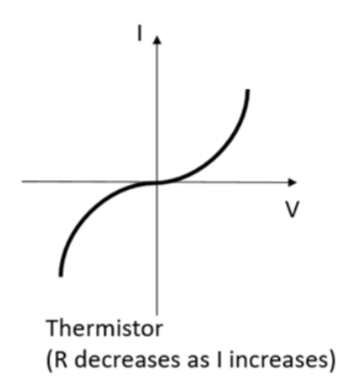
Explain the IV relationship for a thermistor (here, the temperature increases due to the current flowing through the thermistor, so we must explain this step first).
(DO NOT talk about drift velocity)
As the current increases, the electrons collide more frequently with lattice resistor ions, transferring more energy overall to them per second OR as pd increases, electrons gain more energy and transfer more energy to lattice resistor ions.
This causes the resistor ions to oscillate with greater amplitudes, so the temperature of the resistor increases.
As the temperature increases, electrons can gan energy and so more electrons are promoted into the conduction band of the thermistorm so n, the number density of free charge carriers increases.
Thus, current, I=nAvq will increase by a greater factor than the pd.
So, as resistance is the ratio of pd to current, if current increases by a greater factor than pd does, the ratio R=V/I decreases.
Explain the resistance, light intensity behaviour for an LDR.
Long answer
A higher intensity means a greater number of photons incident on the LDR per second, per m².
So as intensity increases, more photons incident per second, means more electrons gain energy from the incident photon per second (note that each electron still gains the same amount of energy from each photon, as each photon energy is proportional to frequency, not intensity).
More electrons are promoted into the conduction band of the LDR per second, so n, the number density of free charge carriers increases.
Current increases.
So, as resistance is the ratio of pd to current, if pd remains constant as current increases, R=V/I decreases.
Short answer
Higher intensity of EM radiation means more electrons gain energy from photons.
Increasing the number density of free charge carriers.
Increasing current, reducing resistance.
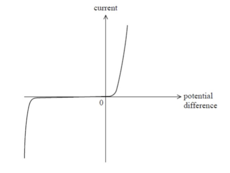
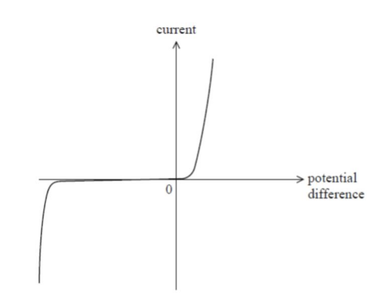
Explain the shape of the diode IV graph.
This is a diode.
It allows current to flow in one direction only.
The diode conducts when the pd is above the threshold voltage, around 0.7V.
For negative pds (in the reverse bias direction), the resistance is very high, but at a very large negative pd, the diode will conduct in the reverse direction.
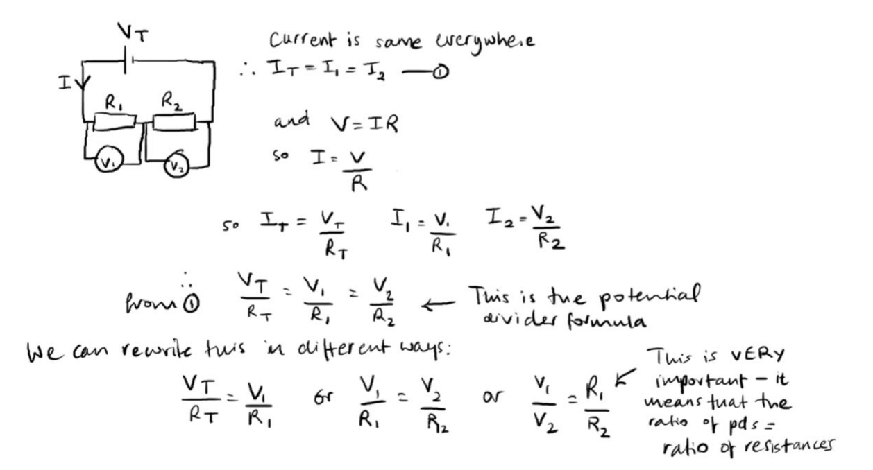
Derive the formula for potential dividers.
Vt/Rt = V1/R1 = V2/R2
(from KCL conservation of charges)
Describe what is meant by a potential divider circuit and draw a circuit diagram to illustrate this.
A potential divider circuit is a simple circuit involving a fixed supply pd that is shared between two resistors.
This can either be two seperate resistors (a) , or a rheostat or potentiometer (b)
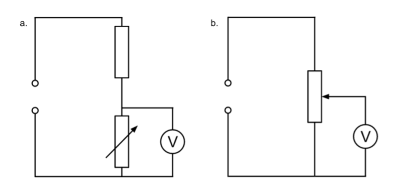
Describe what will happen to the voltmeter reading in circuit a, if the resistance of the variable resistor decreases.
There is a fixed supply pd and the other resistor is of fixed resistance.
When the variable resistor’s resistance increases, the voltmeter reading increases.
This is because the pd is shared in the ratio of the resistances.

Describe how the voltmeter reading in circuit b changes as the slider is moved from the bottom of the resistor to the top.
At the bottom of the resistor, the voltmeter reading would be 0V.
At the top of the resistor, the voltmeter reading would be equal to the supply pd.
Pd is proportional to the length of the wire.

A student moves the slider along the potentiometer. Explain why pd is proportional to the length of the wire,
Resistance is proportional to the length, for a constant cross sectional area and resistivity, R = ρl/A.
The current is fixed as the total resistance in the circuit is unchanged as the slider is moved.
V is directly proportional to R, as V=IR.
So V ∝ R ∝ length
Explain which of these circuits would be better for plotting a graph of current against pd, for plotting an IV graph for the component.
The right hand circuit would be better as it achieves a range of pds and currents from 0V to the EMF of the cell, whereas the left hand circuit has a minimum pd and current that is not close to zero.
For the right hand circuit, the pd across the component can vary from 0V (when the slider is on the left) to the maximum pd of the power supply (when the slider is on the right).
and the current through the component will be 0A, when the slider is on the left and maximum when the slider is on the right.
For the left hand circuit, the component would always receive a share of the fixed total pd, and the curret through it would never be zero.
monomum pd across the component in the left circuit would be V= EMF x R of component / R total, and the minimum current would be EMF/R total.
so you could not plot an IV graph that starts close to zero for the left hand circuit.
Define resistivity.
The resistance of a unit cube.
Describe what resistivity depends on.
Resistivity is independent of dimensions of the wire - it is unique to an individual material only and depends on temperature.
Describe how the resistivity of a thermistor changes with temperature.
Resistivity of a thermistor decreases with temperature (as number density of charge carriers, n increases).
Describe how the resistivity of a metal filament changes with temperature.
[2]
Resistivity of a metal filament increases with temperature (as drift velocity, v decreases due to more frequent collisions between electrons and ions).
Describe how to perform an experiment to determine the resistivity of a wire.
Measure the resistance of a wire using an ohmmeter for different values of the length of the wire.
Measure diameter of wire using micrometer (in three places along the wire, taking an average).
Calculate the cross sectional area of the wire using A = π (d.2)².
Plot a graph of resistance against length, the gradient of the line of best fit will be the resistivity/cross sectional area.
Multiply the gradient by cross sectional area to get the resistivity.
R = ρ/A x l
y = m x
so m = ρ/A
and so ρ = mA