New Material - Modes, B-Flow Imaging, Doppler Artifacts, Interventional & Treatment Instruments, Artificial Intelligence, New Transducers, New Physics Paradigm
 Call Kai
 Learn
Learn Practice Test
 Spaced Repetition
 Match
Match Flashcards
 Knowt Play
1/101

There's no tags or description
Looks like no tags are added yet.
Name | Mastery | Learn | Test | Matching | Spaced | Call with Kai | Chat |
|---|
No analytics yet
Send a link to your students to track their progress
102 Terms
A-Mode
1 dimension - axial to beam
Spike on monitor indicates relative echogenicity - higher amplitude = stronger reflector
Based on range equation
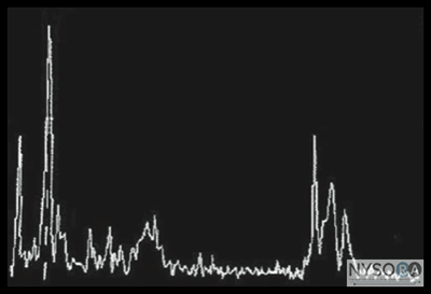
A-Mode X & Y Axis
x-axis: depth
y-axis: amplitude
A-Mode Components
Transducer
Timer/Start Pulse Generator (SPG)
Transmitter/High Voltage Pulse Generator (HVPG)
Receiver
Display (oscilloscope, CRT, imaging screen)
Camera for hardcopy and/or digital storage
A-Mode Instrument Controls
Transducer frequency
Depth
A-Mode Artifacts
Shadowing
Reverberation
Enhancement
Beam width artifact
Velocity artifact
Multi-path
Refraction
Transducer defects
Lack of gel
A-Mode Historical Uses
Echoencephalography,
Cardiology
A-Mode Current Uses
Ophthalmology
Tissue characterization
Non-destructive industrial testing
M-Mode
Single sound beam
Signal amplitude information is converted to dot brightness
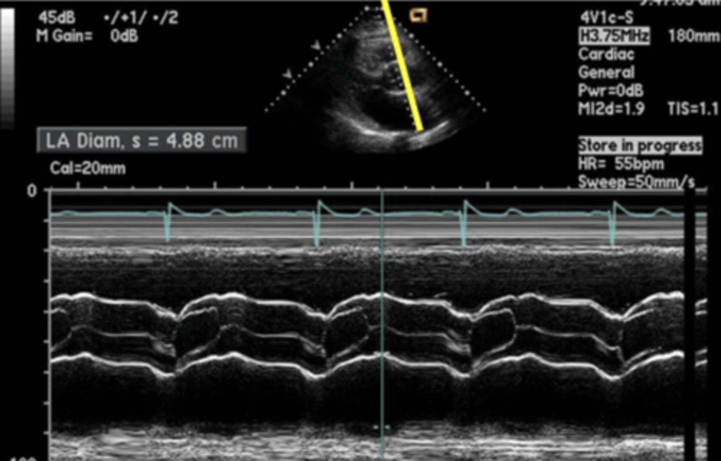
M-Mode X, Y, & Z Axis
x-axis: change over time
y-axis: depth
z-axis: echo brightness
M-Mode Components
SPG/timer
HVPG/transmitter
Transducer
Receiver
Scan converter
Display
Storage - strip chart recorder, camera, or video tape
M-Mode Controls
Transducer frequency
Depth
Gain & TGC
Sweep speed
EKG & respirometer
M-Mode Artifacts
Shadowing
Reverberation
Enhancement
Beam width artifact
M-Mode Uses
Cardiology
Lung
M-Mode Advantages
Easy measurements
Good temporal & axial resolution
Can see several cycles at once
M-Mode Limitations
Very dependent on cursor placement
Only displays one type of motion - no lateral or perpendicular motion
Difficult to identify echo source if B-mode image is not present - scanning blind
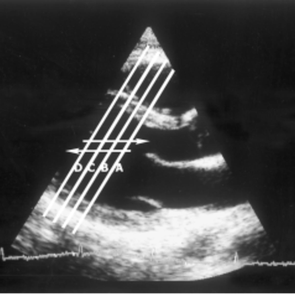
Anatomical M-Mode
Steerable m-mode
Modifies angle to obtain more accurate measurements
Not limited to scan line angles
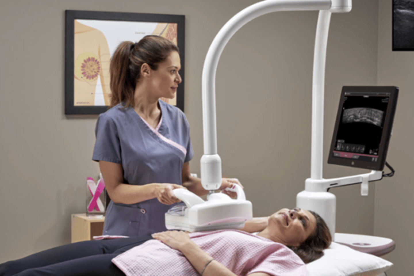
Static B-Mode
Tx beam controlled by sonographer
Amplitude of signal is represented by the brightness of each dot
Large FOV
Static B-Mode Components
SPG/HVPG
Transducer
Receiver
Scan Converter
Display (CRT)
Registration system
Static B-Mode Controls
Transducer frequency
Depth
Gain & TGC
Measurements
*Scanning Movements
Static B-Mode Artifacts
Shadowing
Reverberation
Enhancement
Beam Width Artifact
Velocity Artifact
Multi-path Artifact
Refraction
Transducer defects
Lack of gel
Misregistration
Static B-Mode Uses
OB-GYN
Abdominal
Vascular (Non-Doppler)
Small Parts
Real-Time B-Mode
Tx beam controlled mechanically or electronically
Produces multiple frames of multiple scan lines
Images continuously gathered & refreshed
Reduced FOV
Real-Time B-Mode Components
SPG/HVPG
Beam Former
Transducer
Timer
Receiver
Scan Converter
Display
Storage
Real-Time B-Mode Controls
Transducer frequency
Depth
Field size
Zoom
Measurements
*Focusing
Real-Time B-Mode Artifacts
Shadowing
Reverberation
Enhancement
Beam width artifact
Velocity artifact
Multi-path artifact
Refraction
Transducer defects
Lack of gel
Misregistration
Real-Time B-Mode Uses
Neurosonology
Vascular
Abdomen
OB-GYN
Cardiac
Small parts
Musculoskeletal
Intervention/guidance
Compound B-Mode
More than one scan line may interact with an interface to "build-up" an image from multiple adjacent or overlapping scan lines
Can be used with static or real-time B-mode or EFOV
Abdominal/Multi-Purpose Frame Rate
16 frames/second
Cardiac Frame Rate
30 frames/second
Doppler Frame Rate
40-60 frames/second
3D
Volume b-mode imaging
3D X, Y, & Z Axis
x-axis: long
y-axis: trans
z-axis: reconstructed horizontal/coronal view
3D Image Acquisition
2D freehand - manual volume
3D automated - mechanical volume
Matrix - electronic volume
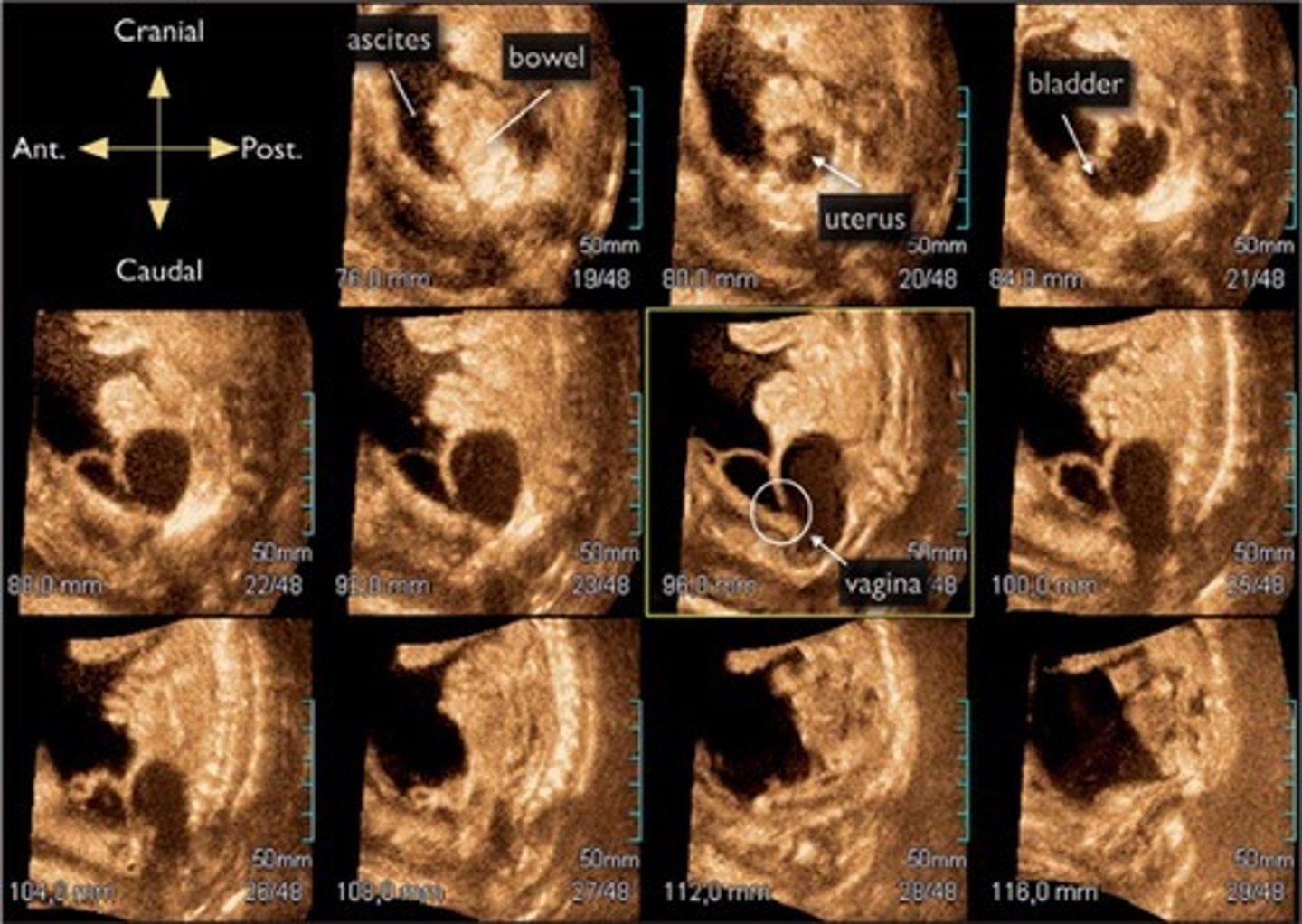
Tomographic View/Slice
3D Uses
Cardiology
Vascular
OB
GYN
Transparent Rendering
Allows us to see through the voxels (2D pixels in a 3D matrix)
Surface Rendering
Provides impression of depth by using brightness and shading
Enhances surface visualization of structures
Render Box
Rectangular box to define echoes for render
Render Line
Marks "top of box"
May be curved
aka reference slice
Inversion
Converts anechoic areas into solids
Surrounding echoes are subtracted or erased
May be used as basis for computer aided volume calculation (VOCAL)
aka cavity mode
STIC
Spatio-Temporal Image Correlation
Used in 4D fetal echo
Voxel
aka axis dot
aka reference dot
aka reference voxel
AOI
Area of interest
ROI
Render of interest
VOI
Volume of interest
MPR
Multiplanar Rendering/Reconstructions
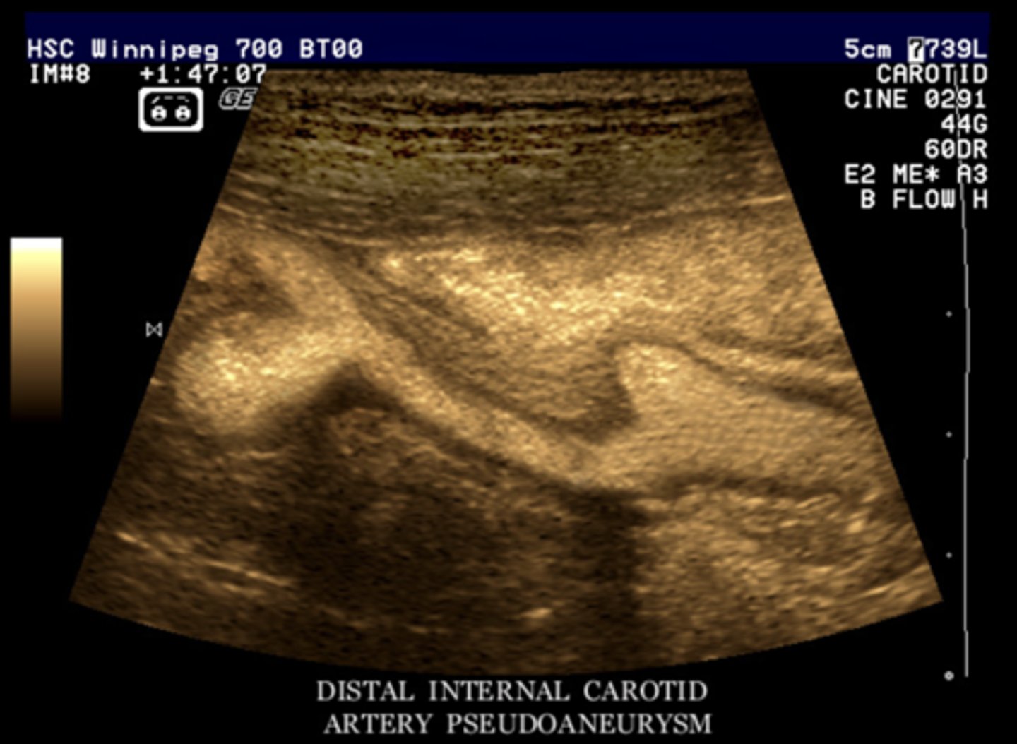
B-Flow Imaging
B-mode imaging with flow without the overlay of color Doppler
Both RBCs & tissues are shown
Angle independent & not based on frequency shifts
Creating a B-Flow Image
Digitally coded sound waves transmitted into body
Returning signals are decoded
Subtractive process is used to separate RBCs from tissue
Weak returning signals from RBCs are enhanced
Tissue signals are equalized
All signals are displayed
B-Flow Imaging Uses
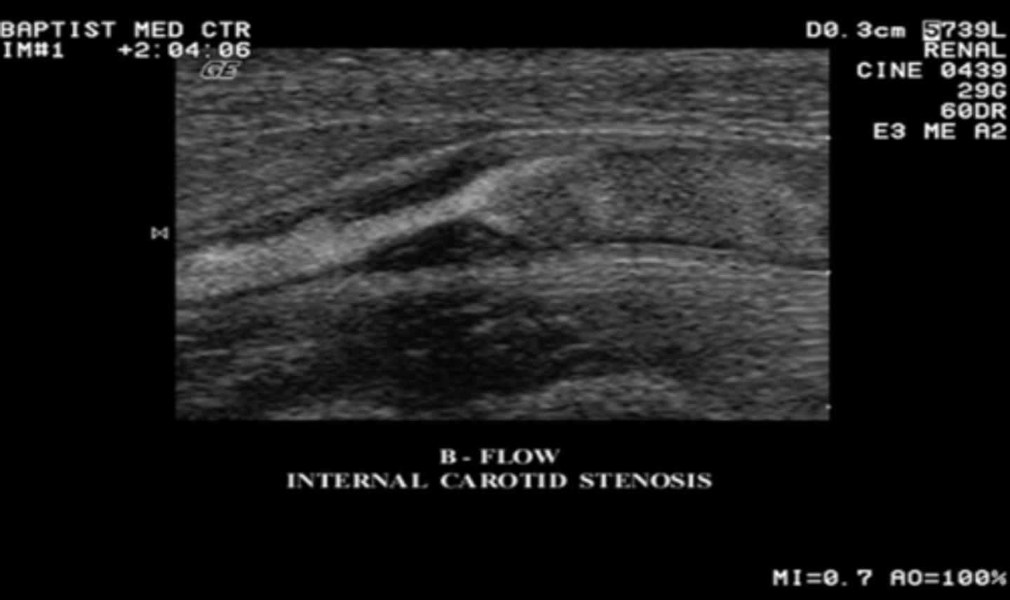
Degree of stenosis
Low flow conditions
Flow in vessels that are perpendicular to sound beam
Characterizing hypoechoic ulcerated plaques
B-Flow Imaging Advantages
Does not alias
Increased cavity of vessel lumen & stenotic areas
High frame rate
Better temporal & spatial resolution
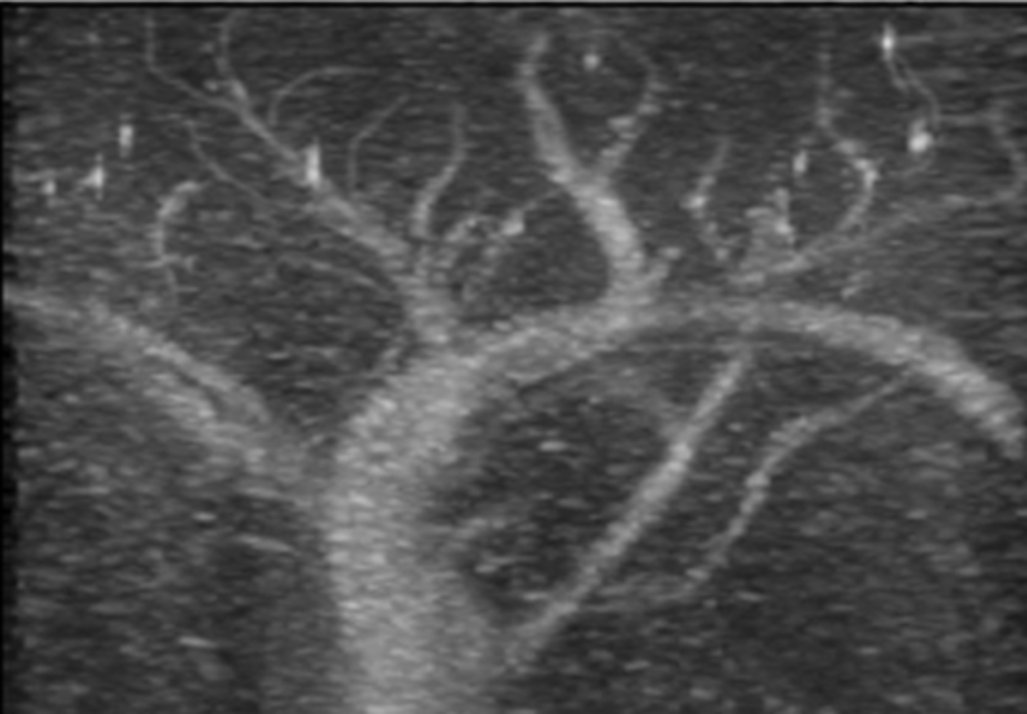
Color Aliasing
Doppler frequency shift exceeds Nyquist limit (max detectible frequency)
"Wrap-around" color display
Seen with high velocity/turbulent areas & stenosis
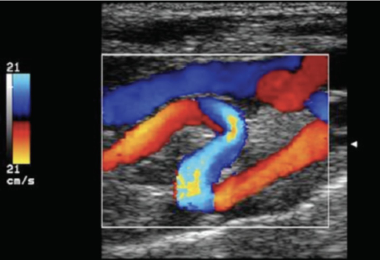
How to Correct Color Aliasing
Lower frequency
Decrease depth
Avoid Doppler angles close to 0°
Incorrect Color Steering/Angle
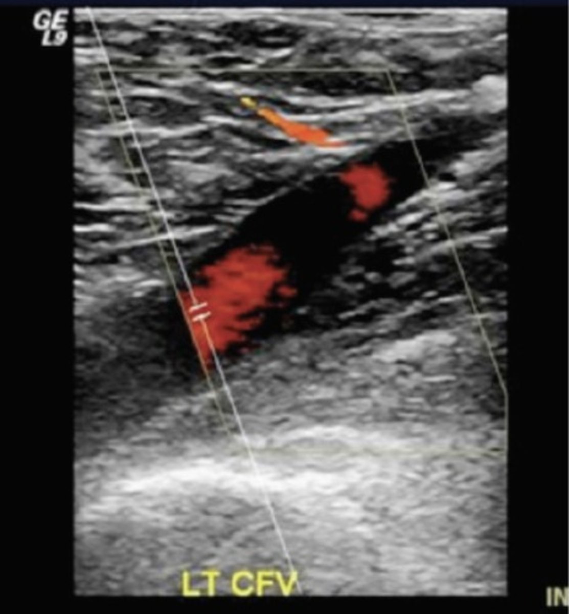
How to Correct Incorrect Color Steering/Angle
Angle color box so it is parallel with vessel/in line with blood flow
Rocking/tilting motions
Over-Gaining Color
Color speckle/bleeding outside of vessel
Typically noise
Over-amplification of signals
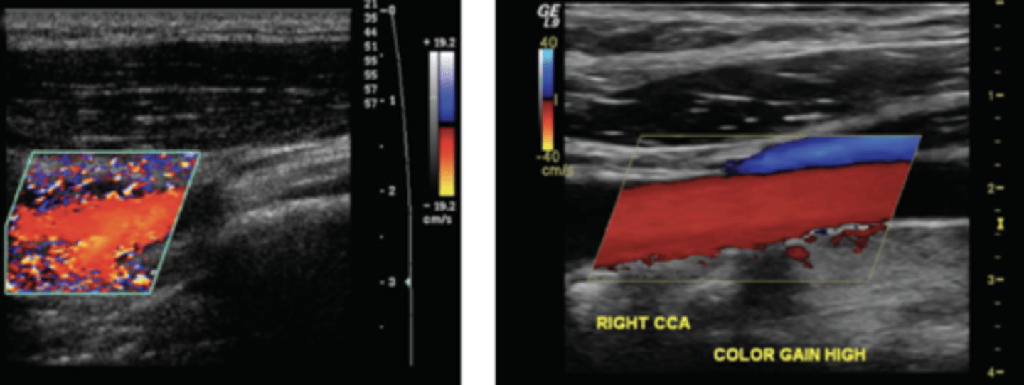
How to Correct Over-Gaining Color
Decrease color gain
Adjust scale/baseline if needed
Under-Gaining Color
Lack/absence of flow - can be mistaken for pathology
Can occur in small vessels or deeper vessels
Under-amplification of signals
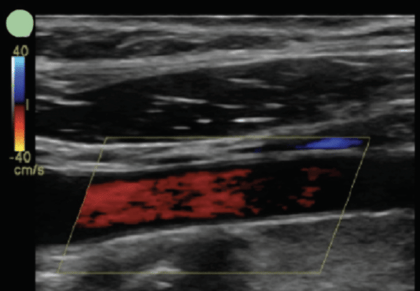
How to Correct Under-Gaining Color
Increase color gain
Set to low flow color Doppler setting
Adjust scale/baseline if needed
Incorrect Color Scales
Too high - low flow not detected
Too low - low flow over-represented as noise/color bleeding
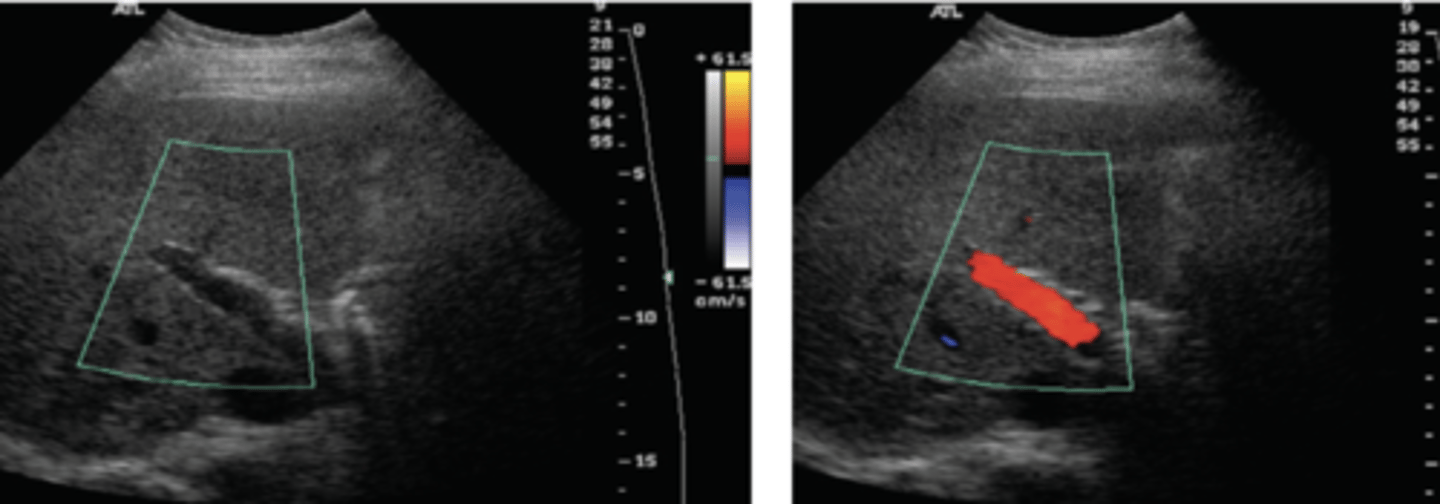
How to Correct Incorrect Color Scales
Decrease scale - more low velocities shown
Increase scale - less low velocities shown
Pseudoflow
Color appears in areas that do not contain blood
Shows movement of other fluids - amniotic fluid, urinary jets, ascites, pleural fluid, etc.
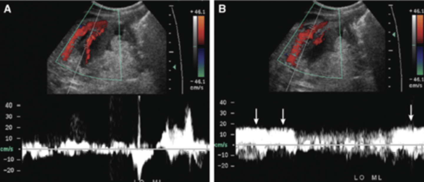
How to Correct Pseudoflow
Evaluate anatomy - is it a vessel or not
Apply spectral Doppler to see if there is a correlating waveform
Flash Artifact
Speckles/flashes of color appear for patient or transducer movements
Also present with bruits/high velocity flows
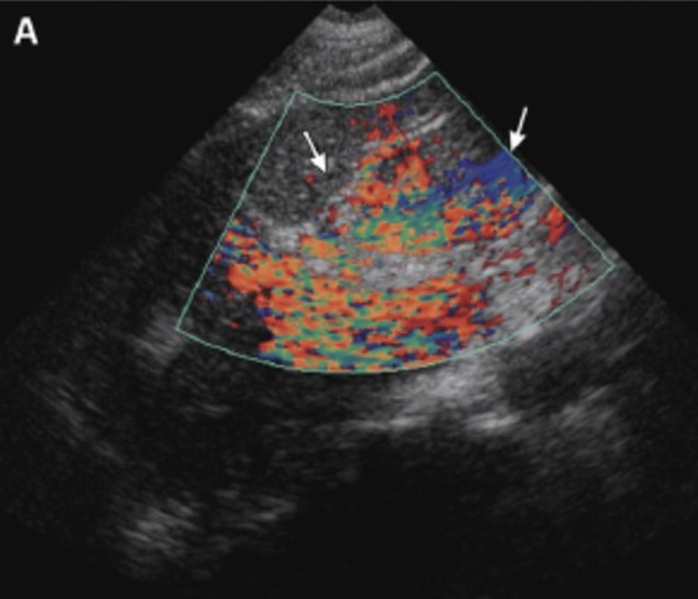
How to Correct Flash Artifact
Have patient stay still/hold breath
Hold transducer steady
Mirror Image
Occurs with strong reflectors
Incorrect structure is shown deeper to actual structure
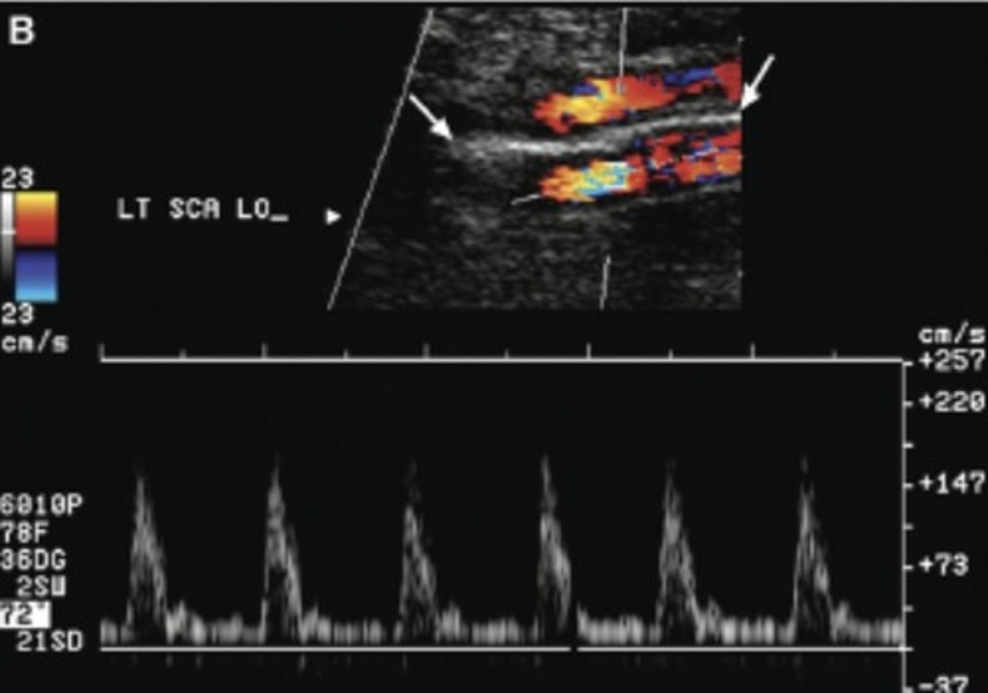
How to Correct Mirror Image
Change scanning position
Color Edge Artifact
Occurs at the margin of a strong, smooth, specular reflector - stones, bones, catheters, foley balloons, etc.
Displayed as persistent color along reflector's edge
More common with power Doppler
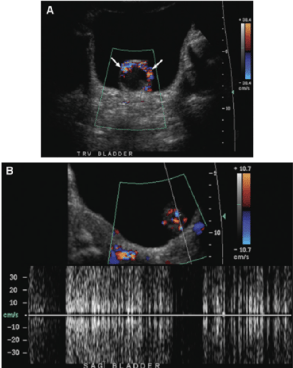
How to Correct Color Edge Artifact
Evaluate without Doppler
Evaluate anatomy
Test with spectral Doppler
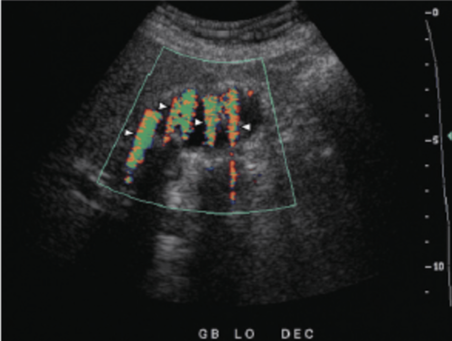
Twinkling Artifact
Color motion/flow imitated behind a stationary strong reflector - stones, calcifications, etc.
Artifact looks like a stream of changing colors below reflector
Good for identifying certain pathologies - GB/renal stones
Spectral Aliasing
Doppler frequency shift exceeds Nyquist limit (max detectible frequency)
Wrap-around display on spectral graph
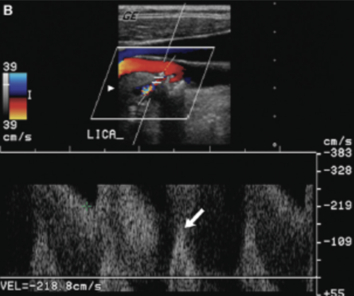
How to Correct Spectral Aliasing
Adjust baseline
Increase scale
Switch to CW if needed
Spectral Mirroring
Presence of flow on both sides of baseline
False flow is usually less amplified and will be the mirror image of true flow
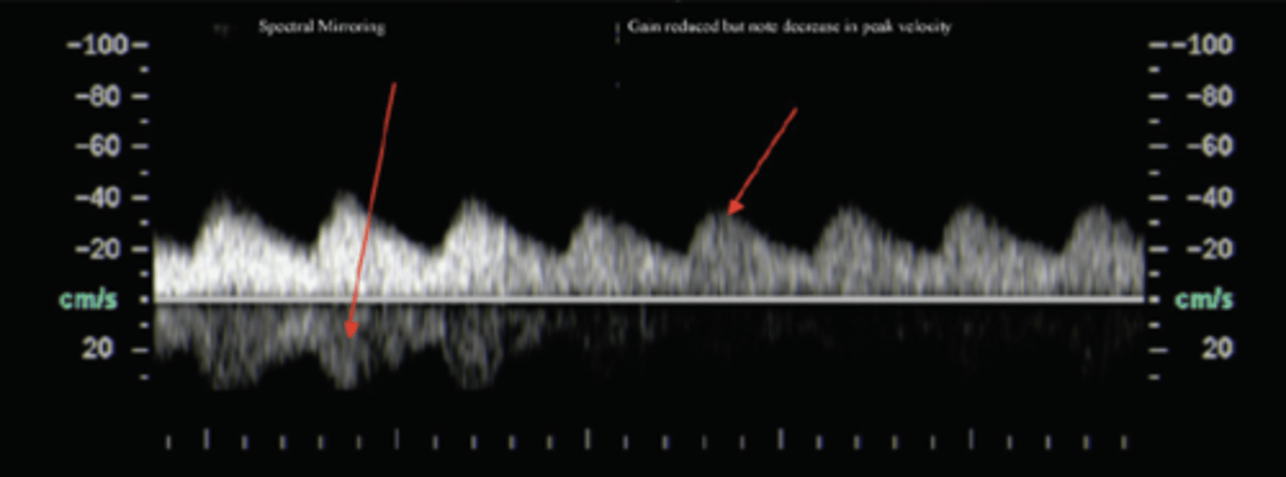
How to Correct Spectral Mirroring
Decrease power
Decrease spectral Doppler gain
Spectral Broadening
Expected when there are multiple velocities being represented in in a given sample region
Occurs with large linear arrays with larger Doppler angles
Some flow is over/underestimated
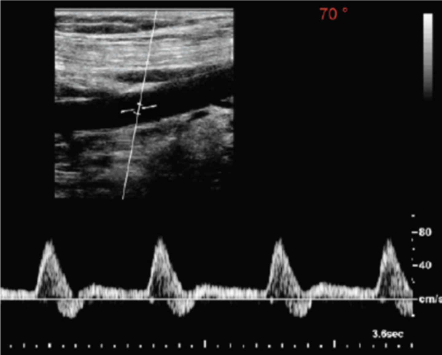
How to Correct Spectral Broadening
Increase depth
Poor Doppler Angle
Can result in over/underestimated peak velocities
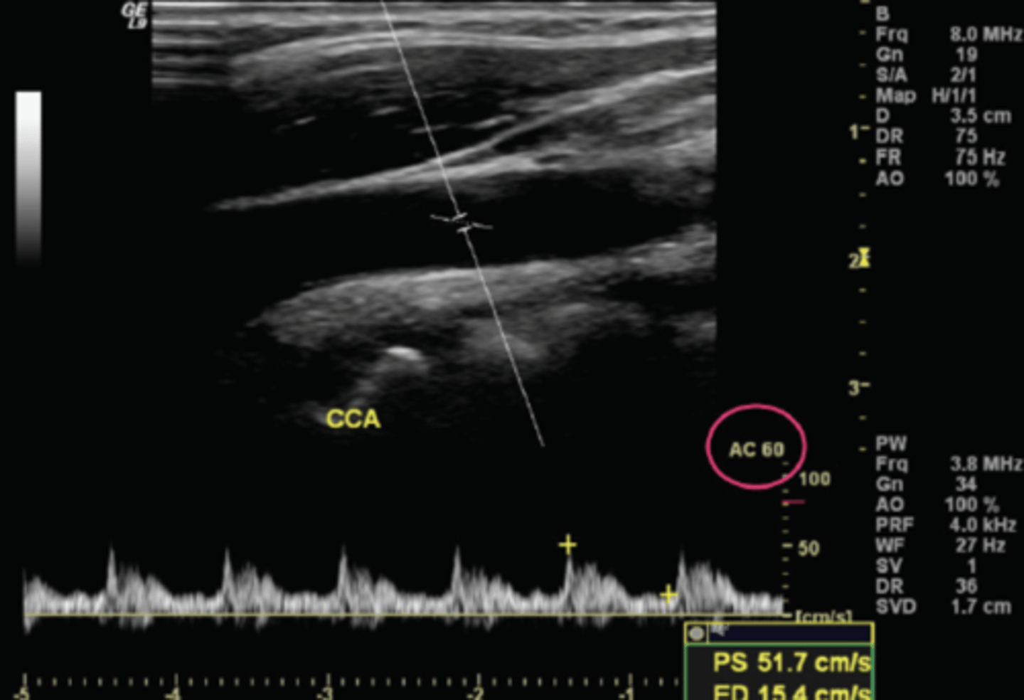
How to Correct Poor Doppler Angle
Rocking/tilting motions to optimize Doppler angle
Poor Doppler Frequency
Too high - poor sensitivity to flow & underestimated velocities
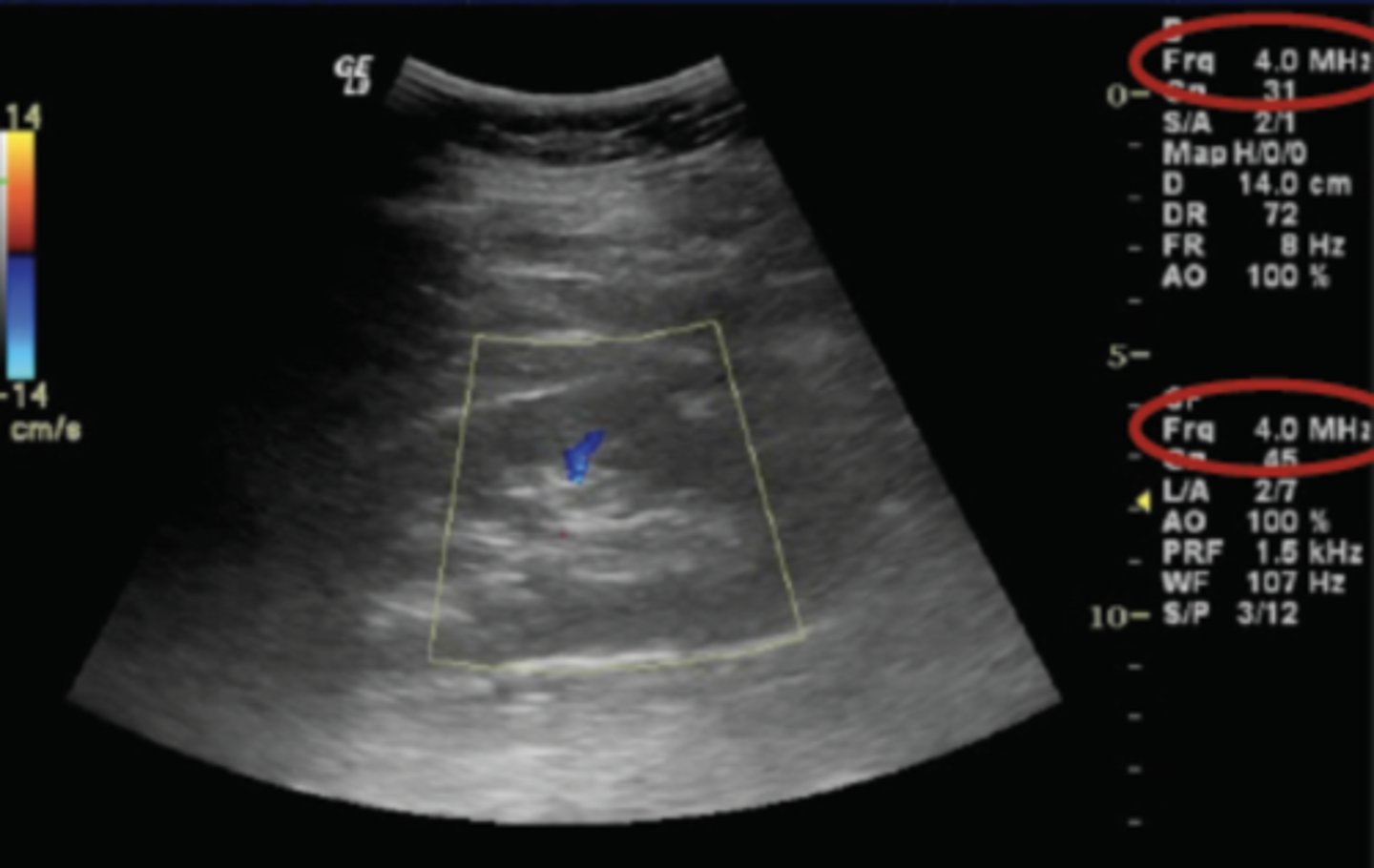
How to Correct Poor Doppler Frequency
Frequency should be as low as possible (unless scanning superficially)
Intravascular/Endovascular Ultrasound
Imaging within blood vessels
Femoral V access in cath lab
Specialized catheter with mini transducer at the tip - produces multi-element electronic (annular) arrays
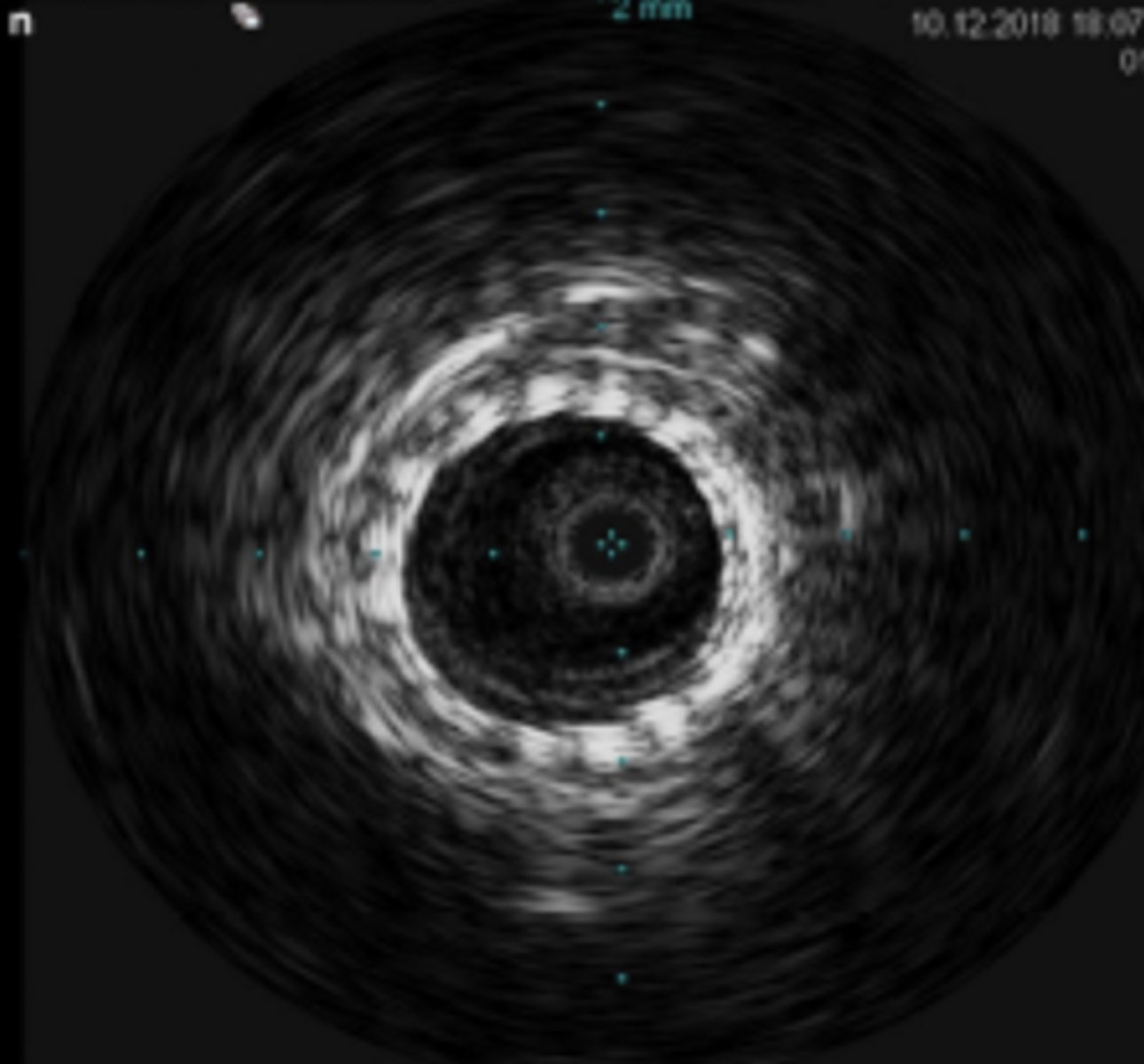
Uses of Intravascular/Endovascular Ultrasound
Supplement to contrast angiography of coronary arteries
Supplement to contrast angiography of peripheral arteries
Evaluation of venous thrombosis
Assessment of AAA before, during and after interventions/repair
Endosonography
Visualizes GI tract or bronchial tract
Radial Tx - visualization
Linear Tx - FNA or therapeutic interventions
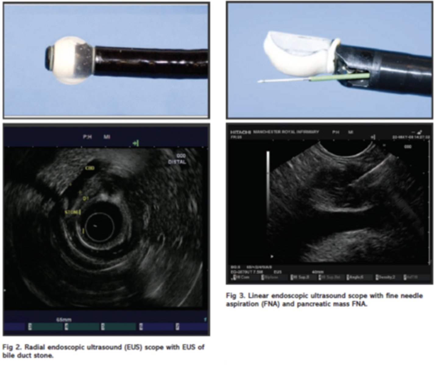
Uses of Endosonography
Staging GI malignancies
Evaluating pancreaticobiliary disease
Evaluating subepithelial abnormalities (GI lining)
Evaluating extraluminal abnormalities (ABNL lymph nodes)
Staging of lung cancer
Therapeutic - Drainings, nerve blocks, drug delivery
High Intensity Focused Ultrasound (HIFU)
Uses heat & cavitation from ultrasound to deliver therapeutic treatments
Performed under ultrasound or MRI guidance
Transducers designed and manipulated to have a very accurate focal spot - goal is to heat/cavitate tissues
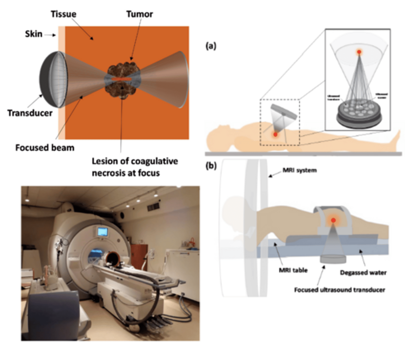
Uses of High Intensity Focused Ultrasound (HIFU)
Benign & malignant tumor ablation
Intervention with essential tremors, Alzheimer's, Parkinson's, Depression/Anxiety, etc...
Disruption of blood brain barrier for delivery of treatment agents into brain tissue
Liquifying intracerebral hemorrhage clot
Advantages of High Intensity Focused Ultrasound (HIFU)
Reduced toxicity compared to other ablation techniques
Less painful & invasive
Lower cost than surgery
Less anesthesia
No scarring
Decreased risk of infection
Disadvantages of High Intensity Focused Ultrasound (HIFU)
Limited by patient movement
Near field heating (possible skin burns) & pain
May have long treatment times
Localized unintended tissue damage
Fusion Imaging
Overlaying/co-registration of images from the same or different imaging modalities
Computer software matches ultrasound imaging with CT, MRI, or PET/CT
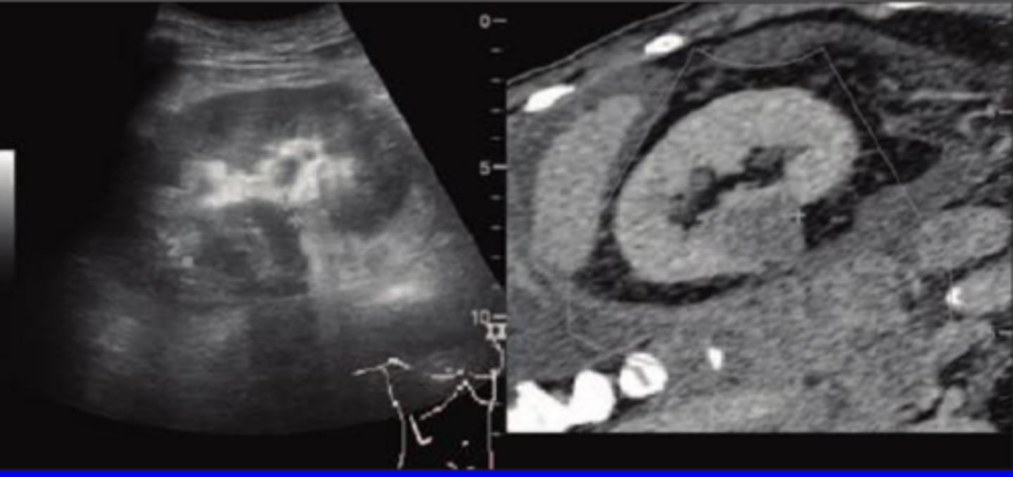
Uses of Fusion Imaging
Liver biopsies
Guiding ablations
Other guidance procedures
Advantages of Fusion Imaging
Improved diagnostic accuracy
More accurate guidance during procedures
Better characterization of pathologies
Disadvantages of Fusion Imaging
Breathing motion real-time registering with static MRI/CT images
Misregistration of data
Still relatively new
Artificial Intelligence (AI)
Use of computer software to develop machine learning - recognition of patterns in medical images to assist with diagnosis - to mimic human cognition
Ways AI is Used in Ultrasound
Used to assist in recognizing patterns in pathology to speed up workflow & aid diagnosis
TIRADS
BIRADS
Scoring liver fibrosis
Fetal lung maturity
Fetal brain
Ventricular wall motion
Detection of heart diseases
Carotid artery intimal thickness
Micromachined Ultrasound Transducers (MUTs)
Tiny transducers
Usually much higher frequencies
Often used for interventional type imaging or newer hand-held transducers that connect to tablets/cell phones - Butterfly
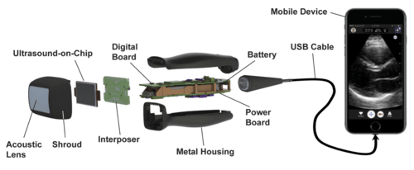
Capacitive Micromachined Ultrasonic Transducer (cMUT)
Parallel-Plate Capacitor
Integrated with circuitry - "plug and play" design
Higher frequency range
Piezoelectric Micromachined Ultrasonic Transducer (pMUT)
Thin piezoelectric film rather than thick crystal
Integrated with circuitry - "plug and play" design
Lower frequency range
Principle 1
Physical beams
1:1 ratio of pulses to scan lines
Pulse length & width determines detail resolution
Best resolution at focus
Adjusting focus affects frame rate & reduces temporal resolution