STAGECRAFT CHAPTER 4
1/43
Earn XP
Description and Tags
LOCK IN LAST QUIZ BEFORE SPRING BREAK
Name | Mastery | Learn | Test | Matching | Spaced |
|---|
No study sessions yet.
44 Terms
scene drawings
drawings that include essential information about the look of the scenery, including the size, construction materials, and assembly information (usually a fraction of a measured foot to represent in actual size)
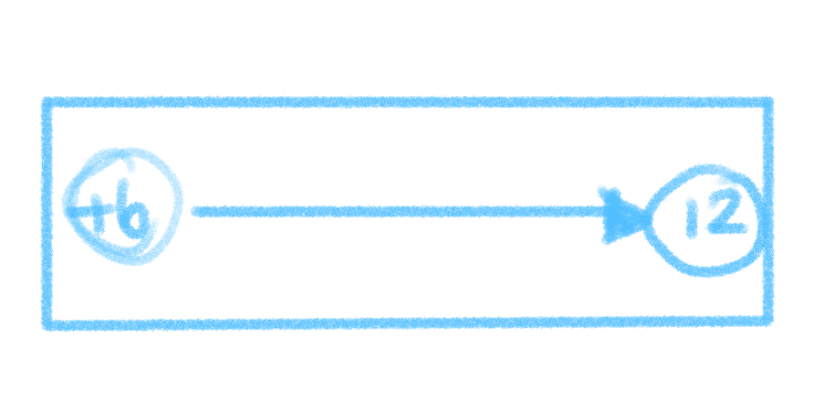
Architect scale
subdivides a foot into twelve inches, like a normal ruler
Engineer scale
1 ft = tenths
Metric scales
working in meters and centimeters
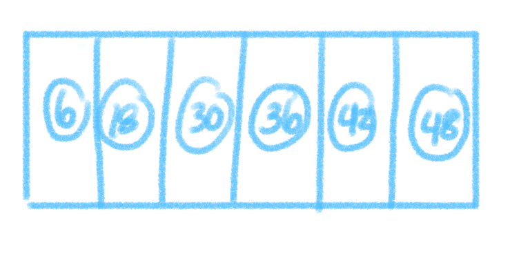
Triangle Scale
has eleven different scales in addition to a full size ruler
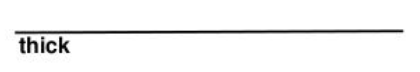
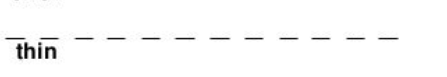
Lines
basic element of any drawing, with thick or thin, straight or curved, solid or dashed that help enhance the readability of drawings
Outline or Object Lines
medium weight solid lines that outline the shape of an object, wall or platform
Hidden Lines
medium weight dashed lines that define the shape of an object that is hidden in the current view
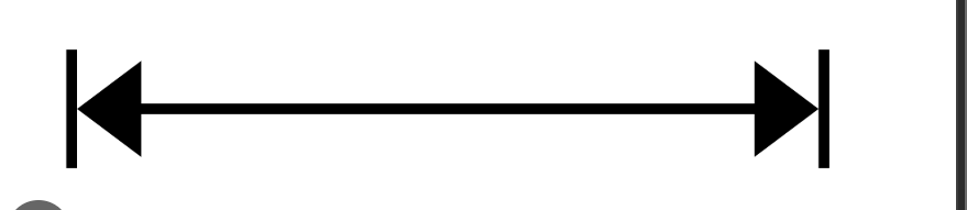
Dimension Lines
lightweight solid lines used to indicate the surface or edge of an object being measured
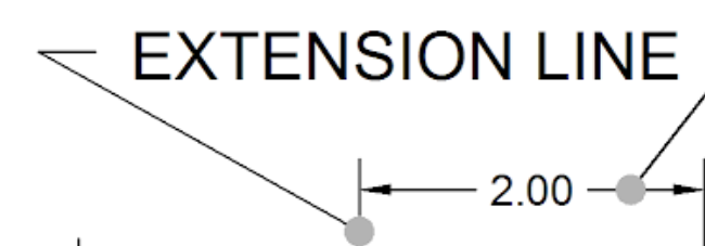
Extension Lines
lightweight lines that are used in conjuction with dimension lines to extend the outline of an object (the vertical line)
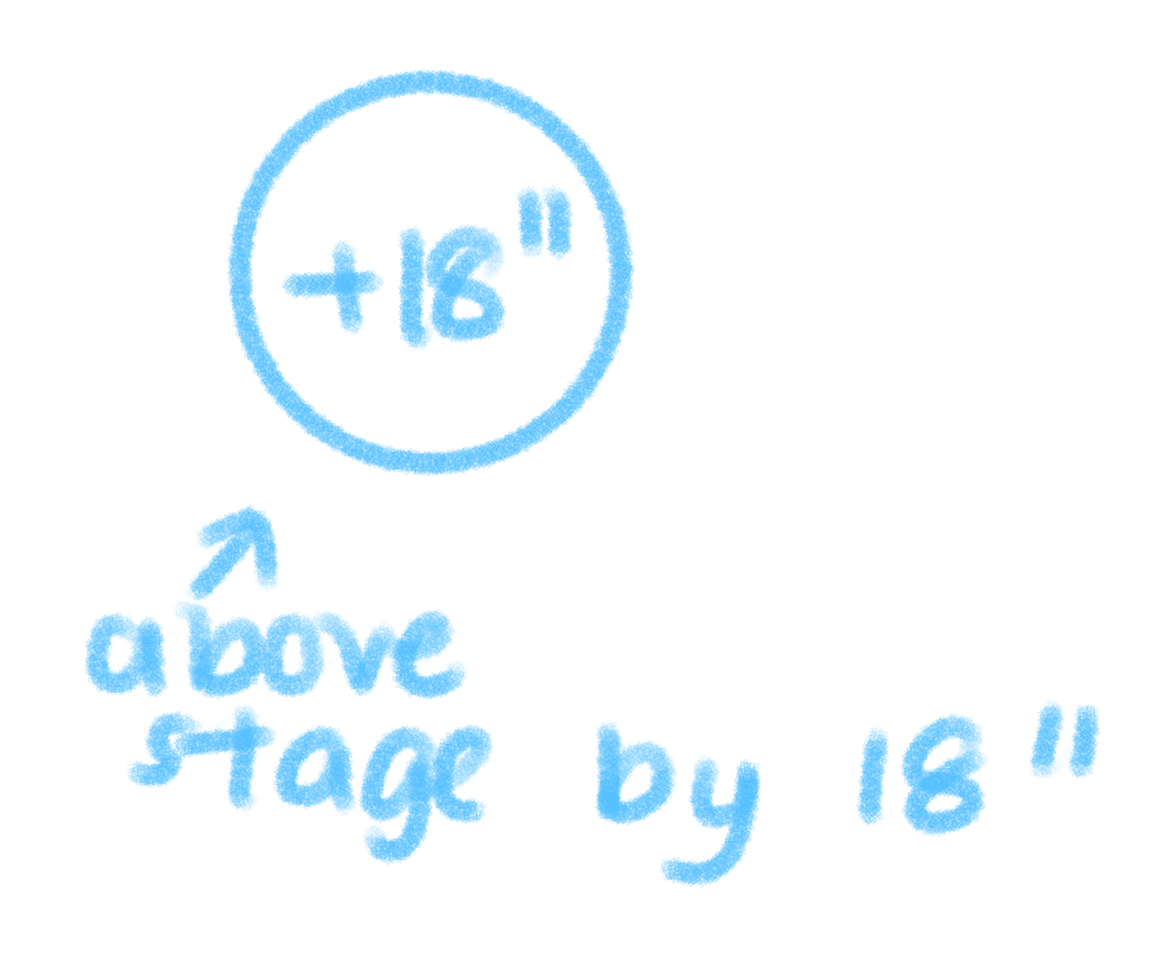
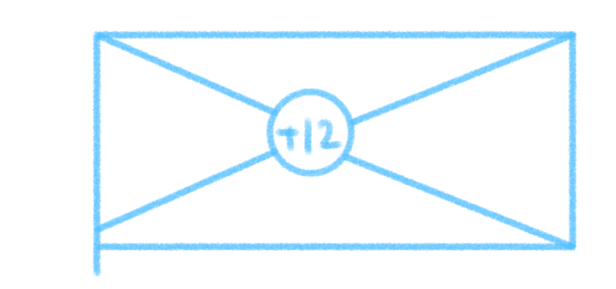
Vertical Dimensions
on a plan view that is indicated by placing a circle around the dimension text to indicate the direction of the stage floor
(+) - height above stage floor
(-) - height below stage floor
Leader lines
lightweight solid lines used to indicate the object or reference point of a note or dimension. . . similar to extension lines to organize information on the drawing
(squiggle line)

Alternate position lines or phantom lines
lightweight dashed lines that indicate an alternative position for a piece of scenery, such as its storage position from scene change or an item being removed for clarity

Center line (CL)
medium weight lines made up of alternate long and short dashes. . . usually describe center of scenery

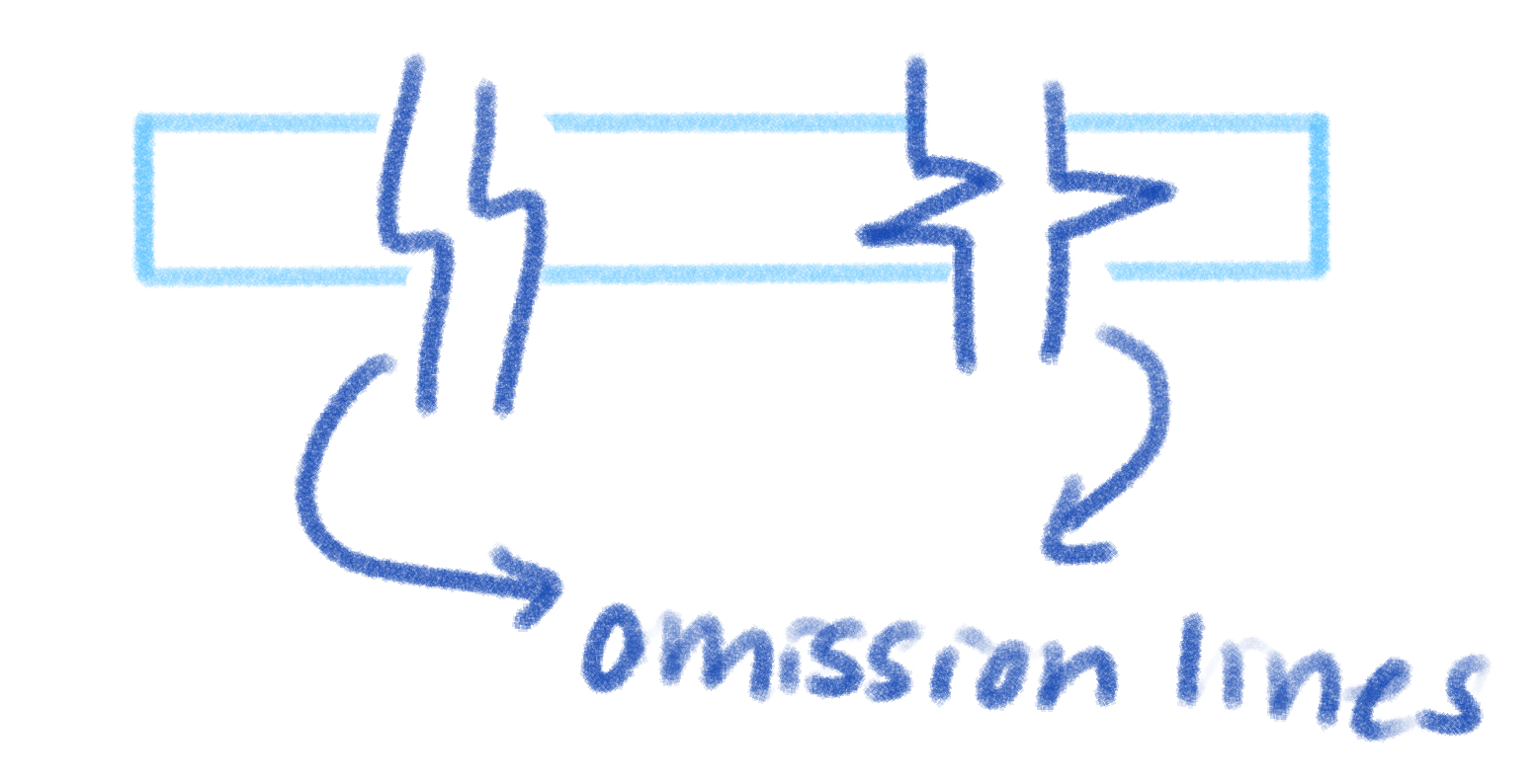
Omission Lines
medium weight solid curved or angular lines that intercept an object line to indicate that part of a drawing or object has been omitted. . . used when a scenic item is larger than the space available for drawing
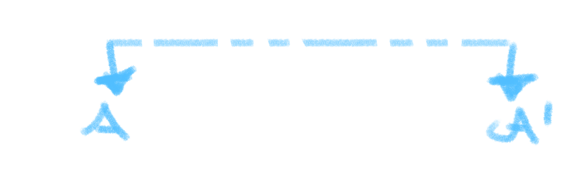
Cutting Plane lines
heavy weight lines alternating between a long dash and two short dashes, and terminating at both ends with arrows that define the imaginary slice of the cutting plane cross section
Section Outlines
heavy weight solid lines that define the edges of an object that are cut by the cutting plane
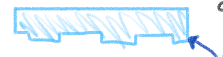
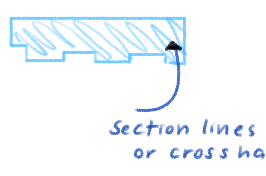
Section lines or cross hatching
regularly spaced, lightweight solid lines used to indicate surfaces or planes that have been cut by the cutting plane
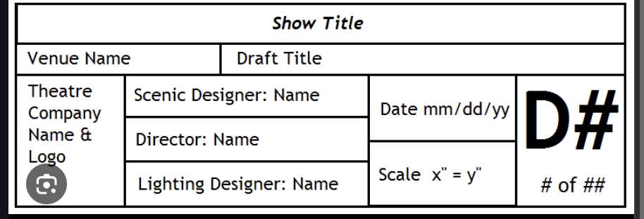
Designer Drawings
organized set of scaled two dimensional illustrations that portray everything about the set
-should have a title block
-has dimensions, materials, and notes for construction
Unframed scenery or drapery (hung flat)

Unframed scenery or drapery (hung with fullness)

Wall (traditional framed flat)

Arch

Door
Sash Window

Casement Window
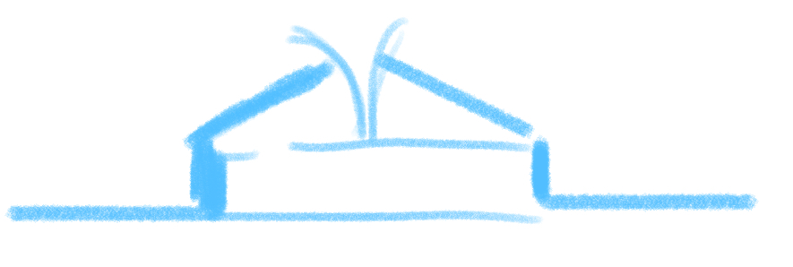
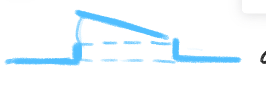
Platform
Ramp
Stair
Title Block
ground plan/floor plan
assembled set in its position change onstage. . . foundation for other drawings in a set, not only a '“bird’s eye” view, but reveals more information about a set
4 Purposes of ground plan
-To locate the set on the stage (two ref lines)
-To show physical relationship of the various parts of the set (uses dimensions and units)
-To determine the audiences horizontal lines
-To act as a reference or table of content, to complete set of drawings
Footprint
reveals platforms or steps
Sections
an entire class of drawings illustrating views that are not visible, provide valuable information for the purpose of construction
(cut three dimensional scene units to reveal the exact shape of the unit or its inner structure)
Elevations
drawings that view an object horizontally, can be front, rear, or side views of a scenic item, providing all pertinent dimensions such as windows or doors
Detail Drawings
A portion of a scenic unit is enlarged to reveal specific detail required for construction
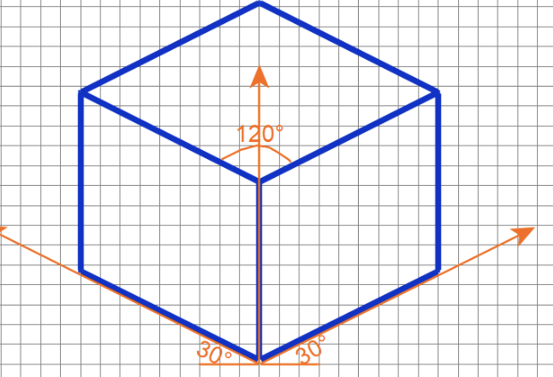
Pictorials
a variety of drawings to help communicate the shape intricate or complex objects (shows 3D dimensions in one drawing)
Isometric drawings
Takes a view that rotates the object 45 degrees to the left or right to reveal a side view or tilts the object up or down to reveal the top or the bottom
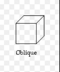
Oblique Drawings
starts with a front elevation of the most complicated face and then the draftsperson selects one side or the other and the top or bottom
Cabinet Drawings
attempt to reduce the distortion of an oblique drawing by proportionally reducing the projected length of the side, top, bottom etc.
Construction drawing
made when particularly complex and intricate scenery is to be built. . . this focuses on components to be used and construction methods
Paint elevation
The designer’s version of the painted set is communicated through use of a painted model (uses precise colors, painting techniques, and details)
Models
effective in illustrating all 3D versions of a set and the spatial relationships among the elements of the set and stage