Logic gates
1/20
There's no tags or description
Looks like no tags are added yet.
Name | Mastery | Learn | Test | Matching | Spaced |
|---|
No study sessions yet.
21 Terms
Logic Gates
Devices that have one or more inputs and generate an output based on a logic operation.
Logic Circuit
A circuit made up of multiple logic gates.
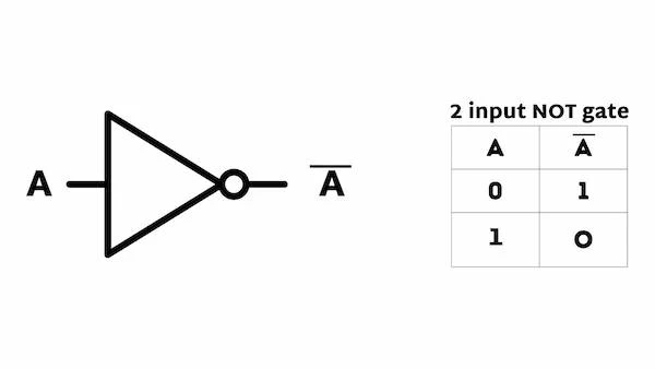
NOT Gate
A logic gate that outputs the inverse of the input; if input is ON, output is OFF and vice versa.
NOT gate diagram
P(output) = not A
The probability output in a NOT gate where output is the inversion of the input.
Inverse
A term related to NOT gate indicating the opposite state of the input.
Boolean NOT
¬A signifies the output of a NOT gate when input A is given.
Output of NOT Gate
If input is ON, the output is OFF (and vice versa).
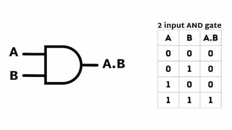
AND Gate
A logic gate that requires both inputs to be ON to produce an output; represented as P = A AND B (A ^ B).
AND gate diagram
P = A AND B
Probability output in an AND gate where both A and B must be true for the output to be true.
Boolean AND
A ^ B
Function of AND Gate
Both inputs must be ON for the output to be ON.
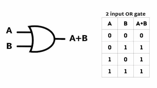
OR Gate
A logic gate that outputs ON if either or both of the inputs are ON; represented as P = A OR B (A V B).
OR gate diagram
Input of OR Gate
If either one or both inputs are ON, the output will be ON.
P = A OR B
Probability output in an OR gate where either A or B must be true for the output to be true.
Boolean OR gate
A V B represents the logical OR operation.
A V B
Symbol representing the OR operation in mathematics.
Truth Table
A table that shows all possible input combinations and their corresponding outputs for a logic gate.
Logic Operation
A calculation performed on one or more binary inputs to produce a single binary output.