Section 4 - Operational Amplifiers
1/35
There's no tags or description
Looks like no tags are added yet.
Name | Mastery | Learn | Test | Matching | Spaced | Call with Kai |
|---|
No study sessions yet.
36 Terms
Operational Amplifiers Picture
lever-shifter, buffers, comparators, adders, subtractors, integrators, differentiators, current source
Properties of Ideal Op Amp
input infinite impedance (Zin = infinity → no current) and 0 output impedance (Zout = 0); infinite gain (|Vout/Vin|)
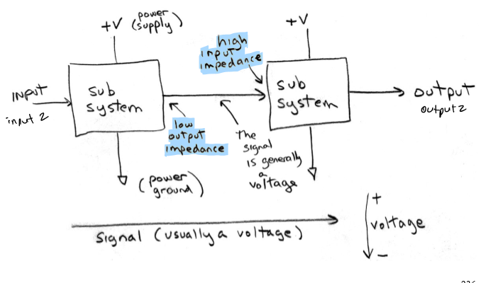
Infinite Input Impedance
reads input V w/o changing it by drawing current
0 Output Impedance
can provide infinite output current w/o affecting V; Vout = V - IR = V
Infinite Gain
= for both inputs so can have single variable A; Vout = A(Vin+ - Vin-), A → infinity
Comparator
single Op amp for comparing V; has a single-sided power supply (+ and ground); open collector output → sink/pull I not source it; no R or C; fast, simple, and digital; open collector output
0 Crossing Detector
a comparator circuit that compares input V to reference (0 V when grounded); crossses 0 (either - → + or + → -); high state (Vin > Vref → + saturation of output) or low state (Vin < Vref → - saturation of output)
Comparators: offset reference voltage
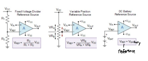
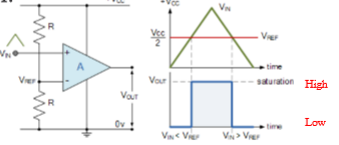
+ Voltage Comparator - Noninverting
Vin > Vref → output will saturate towards + supply rail, Vcc
Vin < Vref → output will change state and saturate at - supply rail, 0 V
Vref = ½ * Vcc
Negative Voltage Comparator - Inverting
Vin < Vref → output will saturate towards + supply rail, Vcc
Vin > Vref → output will change state and saturate towards - supply rail, 0 V
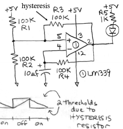
Oscillator
capacitor charges/discharges between 2 thresholds; basically thermoregulator but with a capacitor as “memory” instead of heat
What can a comparator power?
a relay
Advantages of a Comparator powering a relay
switch provides 0 → infinite resistance and up to 1 A; isolation between coil and switch; diode needs to protect comparator from surge in coil; COMPARATOR PROVIDES INFINITE INPUT IMPEDANCE
Comparator vs Op Amp
comparator - output digital/binary; faster; open collector output; usually just + power and ground lowest V
op amp - output analog (basic for linear systems w/ gain); slower; push-pull output (sink or source I → NPN and PNP transistors); has ± power supplies w/ ground in middle
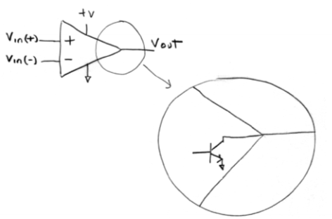
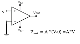
Operational Amplifier
Vout = A (Vin+ - Vin-), A → infiinity; infinite input impedance, 0 output impedance, inifinite gain; 2 input terminals but 1 output hat amplifies difference between inputs; has AC and DC componenets so frequency = 0
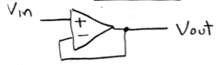
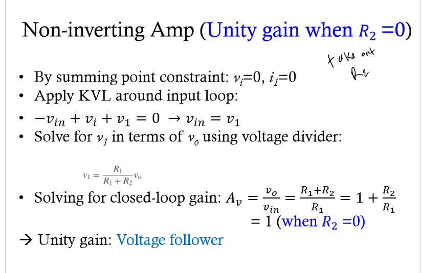
Voltage Follower/Buffer
± inputs equal; 0 input I and large output I; has - feedback; gain is infinite (A = Vout / (Vin - Vout) ); V gain of 1; adds high input impedance so little I drawn
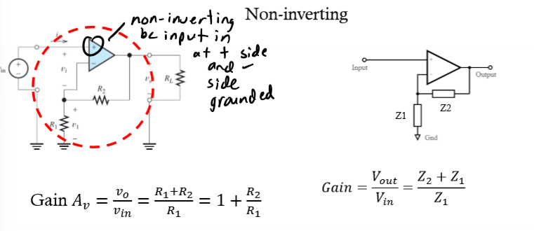
Non-inverting Op Amp
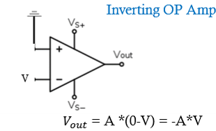
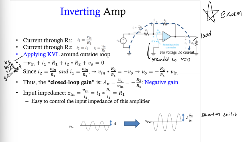
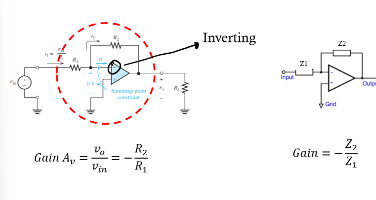
Inverting OP Amp
+ becomes - and - becomes +; sin becomes cos and cos to sin; R2 is feedback R with - feedback; has the summing point constraint
OP Amp - Operational Response
can not have more than supply V; Vout = A * Vd; slope is gain

Summing Point Constraint
differential input V and I are forced to 0; when both grounded inputs are grounded
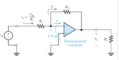
Inverting Amp Example
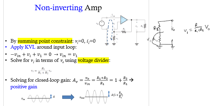
Non-inverting Amp Example
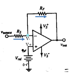
Lever Shifter
remove DC component from Op Amp; use KCL; bc of summing point constraint know that V- = V+ = Vref; by adding Vref DC component of the signal is removed at the output → shifts the level of the signal
Vout = - Rf/Rs * delta Vsensor
Vsensor = Vo(DC) + deltaVsensor (AC) (measured by adding Vref)
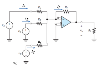
Adder
V at inverting input is 0 (from summing point constraint); apply KCL, KVL, and Ohm’s Law; find eqns. using summing point constraints; V eq. around loop
OP Amps w/ Complex Impedance
math the same but replace R with Z
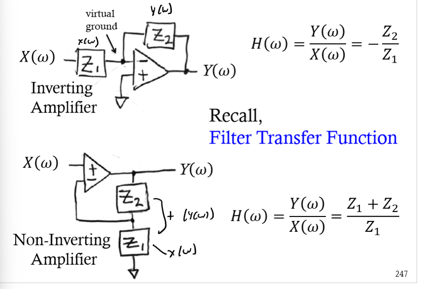
Complex Impedance - Non-inverting
Complex Impedance - Inverting
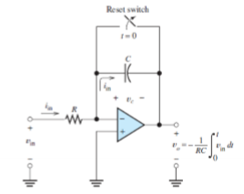
Integrator
V at inverting op-amp input is 0 (summing point constraint); as current comes in, C charges; I through R and C is the same; Vo(t) = -1/RC |0 t (Vin(t)dt;
Op Amp - Low Pass
RC; integrator; gain will drop so that is why it is low pass
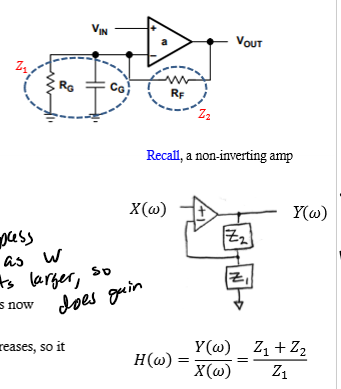
Op Amp - High Pass
as W gets larger, so does gain; gain = 1 + Z2/Z1 = 1 +((1 + jwCR)Rf)/Rg; differentiator
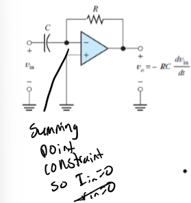
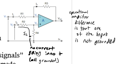
Differentiator
summing point constraint; CR; high pass; Gain = Vo/Vin = -Zr/Zc = -R / (1/jwc) = jwCR; have 2 input sources (used to measure difference between them); reject noise so gains are unequal (A1 does not equal A2) so Vout = A1Vin+ - A2Vin-; 0 output impedance and gain set by R3 and R1; input impedance at V2 is R2 + R4; voltage divider
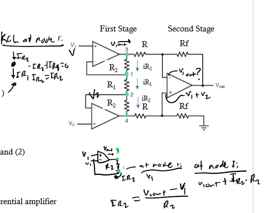
Instrumentation Amplifier
3 op amps but 2 stages; first stage = infinite input impedance and second stage is simply a unity gain (A = 1); use KCL
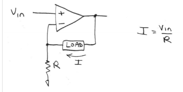
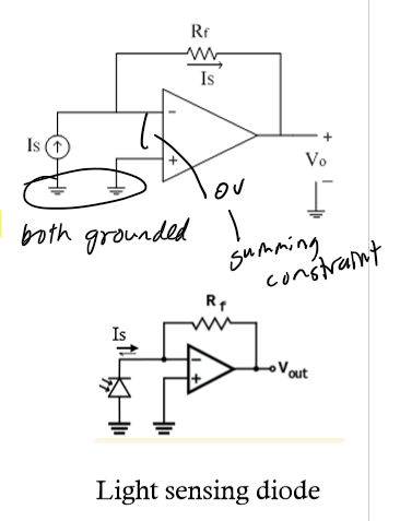
Current → Voltage Converter
Vout = -Is * Rf; used if measuring instrument is capable of only measuring V but you need to measure I; ex. photodiode sensor to measure light intensity
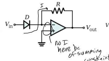
Exponential Amp
Vout = -e^(Vin); diode then R in an inverting op amp
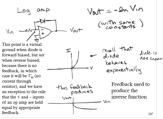
Log Amp
Vout = -ln (Vin); R then diode in an inverting op amp; virtual ground when diode is forward biased but not when reverse biased bc no feedback so Vin (no I through R) and exception to the rule that the + and - inputs of an op amp are held equal by appropriate feedback; feedback used to produce inverse function
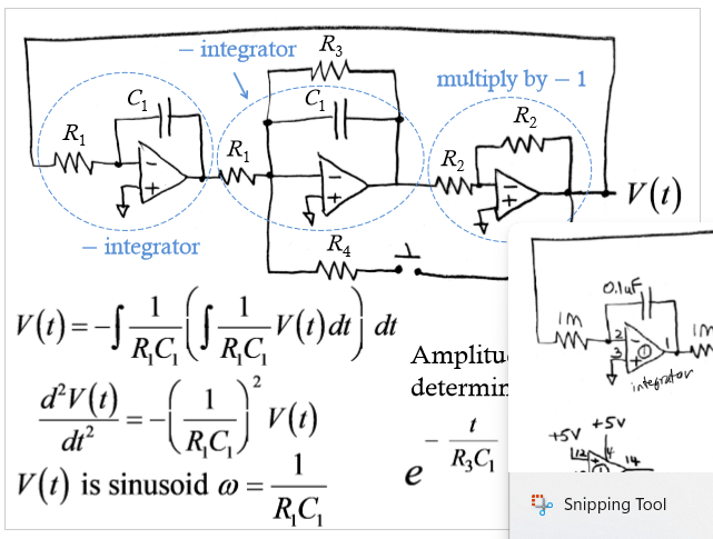
Sinusoidal Oscillator
op amps model any linear differential eq.; all inverting amps w/ R and C