midterm 2 GPR and Resistivity
1/97
There's no tags or description
Looks like no tags are added yet.
Name | Mastery | Learn | Test | Matching | Spaced | Call with Kai |
|---|
No analytics yet
Send a link to your students to track their progress
98 Terms
GPR systsem used for geological investigations… including
detection of natural cavities and fissures
containment plume mapping
road pavement analysis
archaeological investigation
forensic science
GPR (ground pentrating radar) uses…
electromagnetic wave propagation and scattering to image, locate and quantitatively identify changes in electrical and magnetic properties in the ground.
GPR has the highest frequency and …
the highest resolution on subsurface imaging of any geophysical method, approaching centimeters under the right conditions
In the GPR survey
the amplitude and arrival time of the reflected EM pulse are measured
GPR uses electromagnetic waves in the 100-1000MHZ range to…
image the shallow subsurface. It measures travel time of reflected radar waves velocity controlled by the dielectric constant
GPR Fundamentals
Difficult to apply seismics to the study of shallow structure on the scale of 10’s of meters as high frequency signals are needed
GPR usually limited to depths of <20 meters, depending on the conductivity of the subsurface materials.
GPR can investigate >50 meters, for ice in polar regions
GPR Fundamentals (work goes back to 1930s) (QUIZ)
some work goes back to the 1930s but was generally held to be useless for geological applications due to the poor depth of penetration of high frequency radar signals
1970s: GPR was used for limited applications, such as cavity and pipeline dection
1980s-1990s: GPR in archeaological, engineering, and geological problems
improvements in electrical hardware (antennas, amplifiers, fiber optics)
improvements in micro processors to enhance week radar signals
Electromagnetic Spectrum for GPR range
typical frequencies used for GPR range from 25MHZ to 1GHz
Ground Penetrating Radar - Principle
uses short pulses which are transmitted into the ground
Reflections and diffractions of electromagnetic waves occur at boundaries between rock state and objects that have differences in electrical properties
Electric permittivity (dielectric constant), electric conductivity determine the reflectivity of layer boundaries and penetration depth
Propogation of EM Waves
EM waves of GPR are made up of two orthogional vector components
1) an electrical component (E)
2) a magnetic component (H)
In a plane perpendicular to the direction of travel
GPR measurements
Physical Properties
Dielectric Permittivity
considered the diagnostic physical property for GPR
impacts velocity and refelction/refraction of radio waves
significantly impacted by water content
Electrical Conductivity
impacts attenuation (amplitude loss) of GPR signals
Magnetic Permeability
only important if things are very susceptible (generally ignored)
Dielectric Properties
D=eE
water is one of the most polar molecules since the hydrogen atoms develop a positive charge and the oxygen develops a negarive charge
most materials are mixtures so need to consider a combination of properties
Wave Velocity
radar versus siemisic waves
travel times associated with radar waves are shorter than seismic waves
the wavelengths of radar waves are usually short compared to seismic wavelengths
higher resolution of GPR studies
Attenuation constant depends on the physical properties of the media
skin depth- distance at which a wave is reduced to 37% of its original amplitude
skin depth is smaller if the radiowave frequency is higher
skin depth is larger in materials with lower conductivities
skin depth is larger in materials with higher dialectric permittivity
GPR signal contains a range of frequencies
important that they all behave in the same way
othersie the characteristics of the reflected pulses will be affected, making them hard top recognize
Reflection and Transmission of Radiowaves
reflection at conductive object boundaries
many compact objects relevant to GPR applications are highly conductive
when radiowave cannot propogate through object
because of this, when radiowaves reach the interface between the earth and a highly conductive obkective, the wave is completely reflected
Diffraction Hyperbola
A point discontinuity will act as a point source and produce a diffraction that, like a reflection, will produce a hyperbolic event (seismic or GPR)
Radar waves go out in all direction so the strongest reflections may not be directly below the radar antennas
examples include boulders, voids, pipes/drums
anomalous zone produces a diffraction hyperbola
Radar Velocities
in seismic reflection, velocity is found during stacking from the moveout patterns
In GPR, we only have one receiver
fixed offset survey
common midpoint survey
GPR vs Seismic
GPR waves
electromagnetic waves, microwaves/radio waves
depends on EM properties of medium
Frequency = 10-2000Mhz
Wavelength (200 Mhz, granite) 0.65m
Seismic Surveys (Refraction/Refelcttion)
seismic waves
velocity depends on mechanical properties of medium
frequency= 0.1-100Hz
Depends on the source
Wavelength (100 HZ, granite) 50m
What causes a Reflection?
GPR
change in relative permittivity
Seismic Surveys (Refraction/Reflection)
change in acoustic impedance
Transmitter/Receiver vs Geophones
Seismic Refelction
one source
lots of geophones
stacking
moveout
GPR
one source (transmitter)
one receiver
both are antennas
stacking performed by repeating the EM pulse
Moveout
Principles of Operation
radar systems comprise: a signsl generator , transmitting and receiving atennae, a reciever that can record and/or output the signal graphhically
Tx produces a short pulse of waves lasting a few ns. Which travels through the subsurface. At interfaces where there is a change in the electromagnetic impednance the waves are reflected back to the surface and recorfed by the reciever
GPR Equipment
Two types of GPR system
Monostatic: one antyennae is used both transmitter and receiver
Bistatic: separate transmitter and receiver antennae are employed
Frequency range: 10Mhz and 2GHz
Wave speed in vacuum (air): 300,000 km/s or 0.3 m/ns
Travel time of radio waves is of the order of a few 10s to a few 1000s nanoseconds
Monostatic advantagesvs disadvantages
Advantages
single antenna
simple position determination
Disadvantages
limited aperture
Bi-static system advantages vs disadvantages
advantages
seprate antenna positioning
large potential aperture
multiple angles of reception
disadvantages
accurate relative position, information required
accurate time base recquired
relative motion between
Data Acquisition and Processing
GPR systems operate at different frequencies as stated above
some antenna can be used as both transmitters and receivers - known as monostatic/trancievers mode or seperate transmitters and receivers can be used - bistatic mode.
Data Acquisition and Processing (A-Reflection Profiling)
source and reciever antennae moved overground simutaneously at fixed seperation constant offset profiling
several shots are summed at each surface position to improve signal to noise ratio
succesive radar recordings displayed side by side at serperation corresponding to distance moved by antennae
radar reflections displayed on a vertical axis corresponding to time, can be converted to depth if subsurface veolocities known. Sections can be corrected for surface elevations
Data Acquisition and Processing (B-Wide Angle Radar reflection (WARR))
The TX is stationary and measurements are made while the RX is gradually moved away, equivalent to seismic reflection survey methods
This type of survey mode is used to obtain an estimate of the radar signal velocity versus depth in the ground by varrying the antenna spacing at a fixed location measuring the change in travel time to the reflector.
Reflection wave velocity can be determined from the x²-t² method
Data Acquisition and Processing (C-Common Midpoint or Common depth)
The Tx-Rx spacing is increased and reflections from a specific common depth point are gathered, equivalent to seismic reflection survey methods.
objective is to sample each subusrface point sevral times
radar traces are grouped into CDP gathers on the basis of shared source-receiver midpoint bins
Data Acqisition and Processing (D- Transilllumination (radar topography))
borehole radar surveys - one antenna is fixed to a borehole while the other antenna is moved past the stationary antenna in another borehole
radar topography can be performed in boreholes or mines
Resolution
Vertical Resolution: a measure of the ability to recognize individual, closely-spaced reflectors and is determined by the pulse length on the GPR section
rule of thumb is ¼ the wavelength
the wavelength is the velocity of propogation in the material divided by the frequency of the propagation wave
Waves with higher frequencies
higher resolution, attenuate more rapidly than longer period waves
smaller depth penetration
resolution and depth of penetration
wavelength and vertical resolution of 1.5Ghz frequency atenna according to various dielectric constants of the concrete
vertical resolution decreases as a function of depth since deeper travelling EM waves tend to have a lower dominant frequency due to the progressive loss opf higher frequencies by absorption.
energy loss and attenuation
antenna transmission loss
ground coupling effects
reflection and transmission effects
scattering
geometric spreading
absorption and attenuation
GPR limitations
geological materials not well-suited for GPR surveying
any geologic model with high electrical conductivity (or low resistivity)
conductive materials attenuate EM waves
Clay (mud), metallic ores, salt water
geologic materials well suited for GPR surveying
any geological material with low electrical conductivity (or high resistivity)
sand (quartz), nearly all crystalline rocks, freshwater, ice, concrete
Probing Distance Vs. Resolution
higher frequencies give better resolution
lower frequencied give larger probing distance
common sources of noise
many possible signals and paths and the objective is to maximize the target response and mnimize others.
to limit the effects of external sources, the transmiter and receivers are frequently protected by a sheild
Resistivity surverying investigates
variations of electrical resistance, by causing an electrical current to flow through the subsurfae using wires (electrodes) connected to the ground
Two Categories of Electrical Methods
Active and Passive
Active Method
current is applied to the earth, electrical resisitivity (er), induced potential (IP) and electromagnetic (EM)
Passive Method
use naturually occuring energy sources, telluric, magnetotelluric (MT), and self potential or spontaneous potential (SP)
Electrical Methods Applied Current Methods
DC Electrical Resistivity, Induced Polarization, Electromagnetic Induction, Magnetometric Resisitivity
they can use artificial or natural sources, most DC methods utilize artificial sources, electrical methods are probably the most widely used near surface geophysical techniques, for environmental investigations
DC Electrical Resistivity
potential difference (voltage) is measured at various points (direct current)
Induced Polarization (IP)
rise and fall time of the electric potential is measured
Electromagnetic Induction (EM)
Applies AC with a coil and the resulting magnetic feild is measured with another coil
Magnetometric Resisitivity (MMR)
mafnetometer surveys to detect DC magnetic fields produced by DC current flow
Electrical Methods Usage
Petroleum Companies, Mining Companies, Environmental, Groundwater and Egineering Studies
Petroleum Companies
well-logging, but uses of surface-based methods are minor
Mining Companies
heavy users of some types of electrical methods (detections of ore bodies, or environments that commonly host ore bodies)
Environmental, GroundWater and Engineering Studies
commonly used electrical methods (depth to bedrock, depth to water table, clay or sand content, direction of pollution brines)
Primary Objectives of Electrical Methods
determine electrical properties of the subsurface (identify subsurface materials or to determine qualities of the groundwater)
interpret the electrical structure at depth, which is usually assumed to be horizontally layered and to asses its geologic significance
map lateral variations in electrical properties and to asses their geologica significance
Electrical Resistivity Basics
a battery acts as an energy supply, pushing electrons around the circuit
A resistor (R) resists the flow of current I=current put in by the transmitter, R=resistance of the circuit V=measured voltage
For Earth System
inject current into the ground
measure potentials between electrodes
potentials depend upon distribution of subsurface resistivity
ER Method
measures potential difference at points on the earth’s surface by directing electrical current to flow through the subsurface using electrodes connected to the ground
ER method (current)
the current is injected into the earth through current electrodes, and the potential difference is measured between a pair of ptential electrodes. The current and potential electrodes are generally arranged in a linear array
To get current to flow, you must provide a push
the push is a potential difference or voltage, the flow is called the current
Resistance
the amount of potential difference recquired to push a given current is directly proportional to the resistance
Ohms Law
Resistance R=V/I
resistance depends on
the naterial properties such as resistivity… quanitifies how strongly a given material opposes the flow of electric current
the shape of the material that has a current flowing through it R=p I/a or P=Ra/I
Resistance is higher when current is forced through a small area long length
How do we measure resistivity?
apply a known potential difference to a circuit with a resistive material of known length and cross sectional area, then measure the current (w ammeter), this gives the resistance, R use the length and cross-sectional area to calculate
Electrical Methods
resistivity is one of the most variable physical properties
A resisitivity meter
consits of both a voltmeter and a current meter (ammeter).
most systems report the ratio V/I instead of each one separately
it gives the resistance, the resistance can then be converted into resistivity using geometrical parameters based on the type of array
Resisitivity of Geologic Materials
resistivity if the subsurface depends upon:
the presence of certain metallic ores
the temperature of the subsurface
geothermal energy
the presence of archeological features
graves, fire pits, pot holes
amount of groundwater present
amount of dissolved salts
presence of contaniments
% of porosity and permeability
Rock Types and Resisitivty
igneous rocks → higher resistivity
why? only a minor component of pore water
Sedimentary rocks → tend to be the most conductive
why? abundant pore space and fluids
Metamorphic rocks → have intermediate but overlapping resistivity
why? hydrous minerals and fabrics
Rock Types and Resisitivity cont
rocks are usually porous and pores are filled with fluids, mainly water. As the result, rocks are electrolytic conductors.
electrical current is carried through a rock mainly by the passage of ions in pore waters
Electrical Conduction in the Earth
for earth materials, three main types of conduction: electronic resistivity, electrolytic/ionic resistivity, and dielectric permittivity
Electronic Resisitivity (1)
movement of electrons in metals semiconductors like silicate minerals (temperature dependent)
Electrolytic/Ionic Resistivity (2)
movement of cations (+) and anions (-) in opposite directions, salts dissacoiate into ions in solution and move
Dielectric Permitivity (3)
occurs in insulators, which contain no free electrons. displacement of protons/electrons within their orbitial shells. Not important at low frequency (to DC) but important at high frequency for GPR
Rocks and Mineral Resisitivity
resistivity spans several orders of magnitude, making it one of the most widely varying properties of geology
Rocks and Mineral Resistivity Cont
Naturally Occuring Metallic Conductors and Semi-Conductors: graphite, native metals, and many types of sulfides have very low p.
Soils and unconsolidated overburden: p ranging from 10 (wet clays) to >1000 ohms (sands, dry soils)
Sedimentary Rocks: Shale: vary from 10"‘s to a few 100”s of ohms Sndstone: a few 100’s to >1000 ohms Limestone: fresh >1000 ohms
Igenous and Metamorphic Rocks: commonly >1000 ohms, except where heavily fractured and weathered where they commonly drop to several 100’s ohms or less
Factors Influencing Electrical Resisitivity in Rocks
porosoity
pore saturation (% air or gas)
Hydrocarbon Fluid Saturation
Water Salinity (Total Dissolved Solids)
Clay Content
Metallic Sulfide Mineral Content
Fluid Temperature
Rock Matric intrinsic resisitvity
Effects of Clay Minerals
extra water can be tied up in clays minerals
clay minerals supply ions to the groundwater
clay minerals abosrb a layer of highly exchangable cations (enhanced conduction along surface of clay grains) diffused layer further out. Not strongly bound, free to move in E-Field
All rocks containing (wet) clay minerals exhbiti low resistivity
Archies Law
empirical relationship definifng bulk resisitivity of a saturated porous rock
Factors that will DECREASE the resistivity of a rock
add more pore fluid
Increase the salinity of the pore fluid - more ions to conduct electricity
Fracture rock to create extra pathways for current flow
Add clay minerals
Keep fluid content constant but improve interconnection between pores
Factors that will INCREASE the resistivity of a rock
Remove pore fluid
Lower salinity of pore fluid
Compaction-less pathways for electric current flow
Lithification - block pores by deposition of minerals
Keep fluid content constant but decrease connection between pores
How is current distributed?
the fraction of the total current (if) penetrating depth z for an electrode seperation of d is …
the greater the electrode seperation, the greater the depth to which a given percentage of current penetrates
Subsurface Current Paths
current penetration depends upon current electrode seperation
about 70% of the current applied by two electrodes at the surface stays within a depth equal to the seperation of the electrodes
Typically electrode spacing is 2x your target depth but depends on electrode spread (array)
Electricity follows the path or area of least resistance
Fundamental principle (conservation of charge): all the current that goes into a body must come out. there are no sources or sinks of current anywhere, except at the current electrode itself
Depth of Current Penetration
By increasing the electrode spacing, more of the injected current will flow to greater depths
Current Flow - Two Layer Medium
When p2>p1, the current flow lines are more closely spaced in layer 1. current density is higher in layer 1
when p1>p2, the current flow lines are more closely spaced in layer 2. current density is higher in layer 2
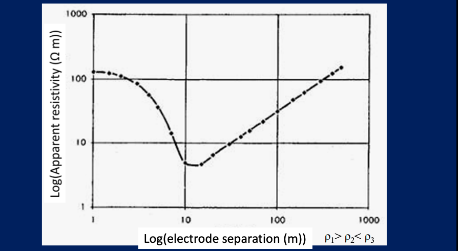
Apparent Resistivity
in a heterogenous medium, the measured resistivity is apparent resistivity which is a function of the form of the inhomegeneity and of the electrode spacing and surface location.
it is dependent on the resistivity along the entire path that the current traverses.
Electrode Arrays/Spreads
Electrode Array- consists of two electrodes at which DC current flows into and out of the ground plus two electrodes between which the potential difference at the surface is measured,
The apparent resistivity measured by different arrays is not the same because the geometric factor K is different
Choice of the best Array depends on
the type of structure to be mapped
sensitivity to the resistivity meter
background noise level
Choice of the best array things to be considered
depth of investigation
sensitivity of the array to vertical and horizontal structures
horizontal data coverage
signal strentgth
Two main types of resisitivity survey methods
A- Vertical Electrical Sounding (Sounding Mode)
B- Constant Seperation Traversing (Profiling Mode)
A: Vetrtical Electrical Sounding
expanding spread traversing
depth profiling
electrical drilling
resistivity sounding
B: Constant Seperation Traversing (profiling mode)
constant spread traversing
electrical mapping
resistivity profiling
Vertical Electrical Sounding (VES)
measurements are repeated as array is expanded about a fixed point, mantaining the relative spacing of the electrode
used to determine mainly the depth variation in resistivity
used to find overburden thickness, aquifers, and other horizontal structures
Wenner Array
All four electrodes have to be moved for wach measurement
Dipole-Dipole Array
rarely used for VES surveys
Schlumberger Array
potential electrodes are kept fixed until measured voltage decreases to low values as potential gradient in ground falls with increasing current electrode separation. then potential electrodes are moved and the process is repeated
Examples of Resistivity Data - VES
apparent resistivity usually plotted on logarithmic scale against electrode seperation
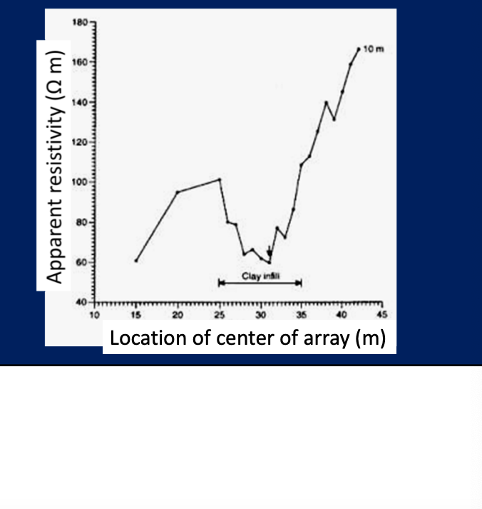
Constant Seperation (spread) Traversing (CST)
measurements are repeated as array is moved along a profile with electrodes mantained at fixed distances
used to determine lateral variations in resistivity
used to detect shear zones, faults and other vertical boundaries
acqusition can be simplified by laying out more than four electrodes and using a subset for reading
Examples of Resisitivity Data - CST
resistivity values are plottedon linear scale against locatiion of centre of array along profile
Sources of Noise in the Data
Instrument Noise
Cultural Features
Telluric Currents - naturually occurriing earth currents
self potentials - generally caused by either geochemical reactions or greater than normal subsurface fluid flow
magnetolleuric currents - electromagnetically induced by naturally occurring or man-made magnetic fields
may be unavoidable
Current Induction in Measurement Cables (noise in data)
An AC current flowing through the cables connecting the current source to the current electrodes can produce an induced current in the cables connecting the voltmeter to the voltage electrodes, thereby generating a spurious voltage reading
can be reduced by using arrays where current and measurement wires dont overlap
Geologic Noise
Near surface variations: can dominate response thus masking signature of deeper targets
Topography: currents will be focused under valleys and dispersed under hills, thus causing perturbations in measured voltages. can think of in terms of charge build up on topographic interfaces
Field Procedures
Survey Design - depends on the specific characteristics of the site and the objective of the survey
Common Modes of Resistivity Survey:
Sounding Mode: to map the depths and thickness of stratigraphic units
Profiling Mode: lateral electrical resistivity contrast, such as lithogic contrast
Sounding Profiling Mode: electrical resistivity varies both vertically and horizontally, such as in contaminant plume mapping
Application to Location of Permafrost
Permafrost represents significantly difficulty to construction projects due to exacavattion problems and thawing under construction. Ice has high resistivity og 1-120 ohm. For example, in Fair banks Alaska, they need to identify pemafrost prior to construction of road cutting