Aircraft Structure and Design Overview
1/348
There's no tags or description
Looks like no tags are added yet.
Name | Mastery | Learn | Test | Matching | Spaced | Call with Kai | Chat |
|---|
No analytics yet
Send a link to your students to track their progress
349 Terms
Weapon Drop
Firing of weapons not included in sizing analysis.
Specific Fuel Consumption
Fuel consumption rate divided by thrust.
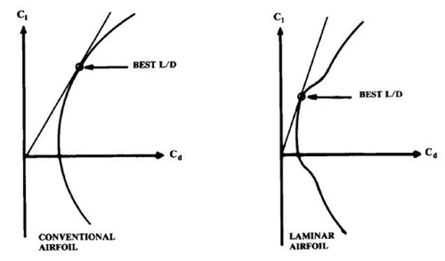
Lift-to-Drag Ratio
Overall aerodynamic efficiency measure of design.
Conceptual Design
Initial phase addressing basic design questions.
Preliminary Design
Phase after major design changes are completed.
Detail Design
Phase where actual parts are fabricated.
Lofting
Mathematical modeling for proper fit of aircraft parts.
Preliminary Weight Estimate
Structural weight is 30-35% of total weight.
Design Take-off Gross Weight
Total aircraft weight at mission start.
Airfoil Thickness Ratio
Maximum thickness divided by chord length.
Mission Fuel
Fuel available for mission performance.
Trapped Fuel
Fuel that cannot be pumped from tanks.
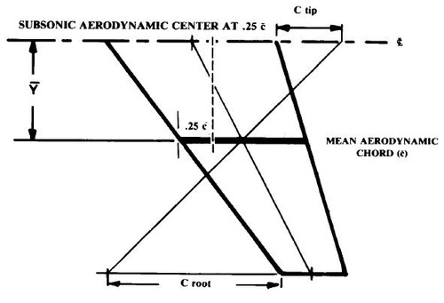
Aerodynamic Center
Point where pitching moment remains constant.
Reynold's Number
Ratio of dynamic to viscous forces in fluid.
Twisting/Washout
Wing design to stall first at the root.
Design Lift Coefficient
Lift coefficient for optimal airfoil performance.
Airfoil Thickness Ratio Effect
Thickness affects wing weight and drag characteristics.
Fat Airfoils
Stall occurs from trailing edge at high angles.
Moderate Thick Airfoils
Flow separates at small angles, causing stalls.
Very Thin Airfoils
Stall occurs at low angles due to flow detachment.
Mean Camber Line
Line equidistant from upper and lower airfoil surfaces.
Thickness Ratio Formula
Thickness ratio calculated as t/c.
Aspect Ratio
Ratio of wingspan to average wing width.
Taper Ratio
Ratio of tip chord to root chord.
Span
Distance from one wingtip to the other.
Airfoil Thickness Ratio
Ratio of airfoil thickness to chord length.
Tip Vortex
Swirling airflow at wing tips causing drag.
Stall Angle of Attack
Angle at which airflow separates, causing loss of lift.
Leading Edge Sweep
Angle of wing leading edge relative to the aircraft.
Induced Drag
Drag caused by lift generation, varies with aspect ratio.
Lift-Curve Slope
Rate of lift increase with angle of attack.
Pitch Attitude
Angle between aircraft's longitudinal axis and horizon.
Wing Weight
Weight of the wing structure, increases with aspect ratio.
Quarter-Chord Line Sweep
Sweep angle measured at quarter chord point of wing.
Oblique Wings
Wings with one swept aft, one swept forward.
Wave Drag
Drag due to shock waves at transonic and supersonic speeds.
Critical Mach Number
Speed at which airflow over wing reaches Mach 1.
Variable Sweep
Wing design allowing adjustment of sweep angle.
Pitch Up
Tendency to uncontrollably increase angle of attack near stall.
Subsonic
Speed less than 0.25 times the speed of sound.
Supersonic
Speed greater than 0.4 times the speed of sound.
Aerodynamic Twist
Adjusts lift distribution to prevent tip stall.
Geometric Twist
Actual change in airfoil angle along the wing.
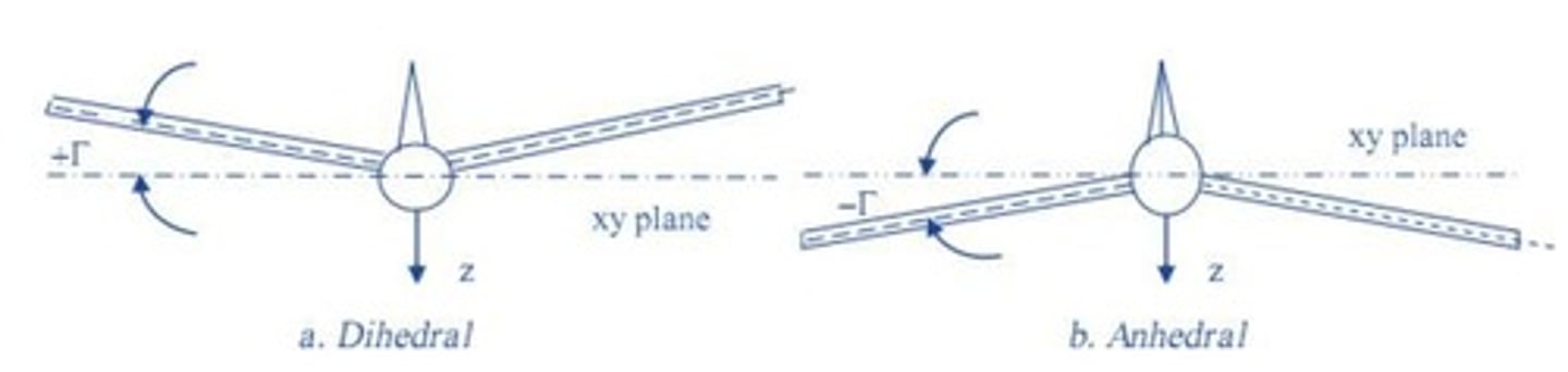
Dihedral
Angle of wing relative to horizontal plane.
Taper Ratio
Ratio of tip chord to centerline chord.
Wing Incidence
Pitch angle of wing concerning fuselage.
Dutch Roll
Yaw and roll oscillation due to dihedral effect.
Compressibility Drag
Drag increase due to air compressibility effects.
Induced Drag
Drag caused by lift generation.
Tip Stall
Stalling occurring at the wingtip first.
Wing Weight
Weight of the wing structure impacting performance.
Ride through Turbulence
Ability to maintain control during turbulent conditions.
Cockpit Visibility
Pilot's ability to see from the cockpit.
Wing Fuel Volume
Amount of fuel stored in the wing.
Landing Attitude
Aircraft orientation during landing phase.
Spiral Stability
Aircraft's ability to maintain a steady turn.
Ground Clearance
Distance between wing and ground during landing.
Asymmetric Stall
Uneven stalling across the wing span.
Lateral Control at Stall
Control effectiveness during stall conditions.
Wing Size
Influences take-off and landing performance.
Biplane Wings
Two wings stacked for increased lift efficiency.
Wing Loading
Weight supported by wing area affecting performance.
Lift-to-Drag Ratio
Comparison of lift generated to drag experienced.
Span Ratio
Ratio of shorter wing to longer wing.
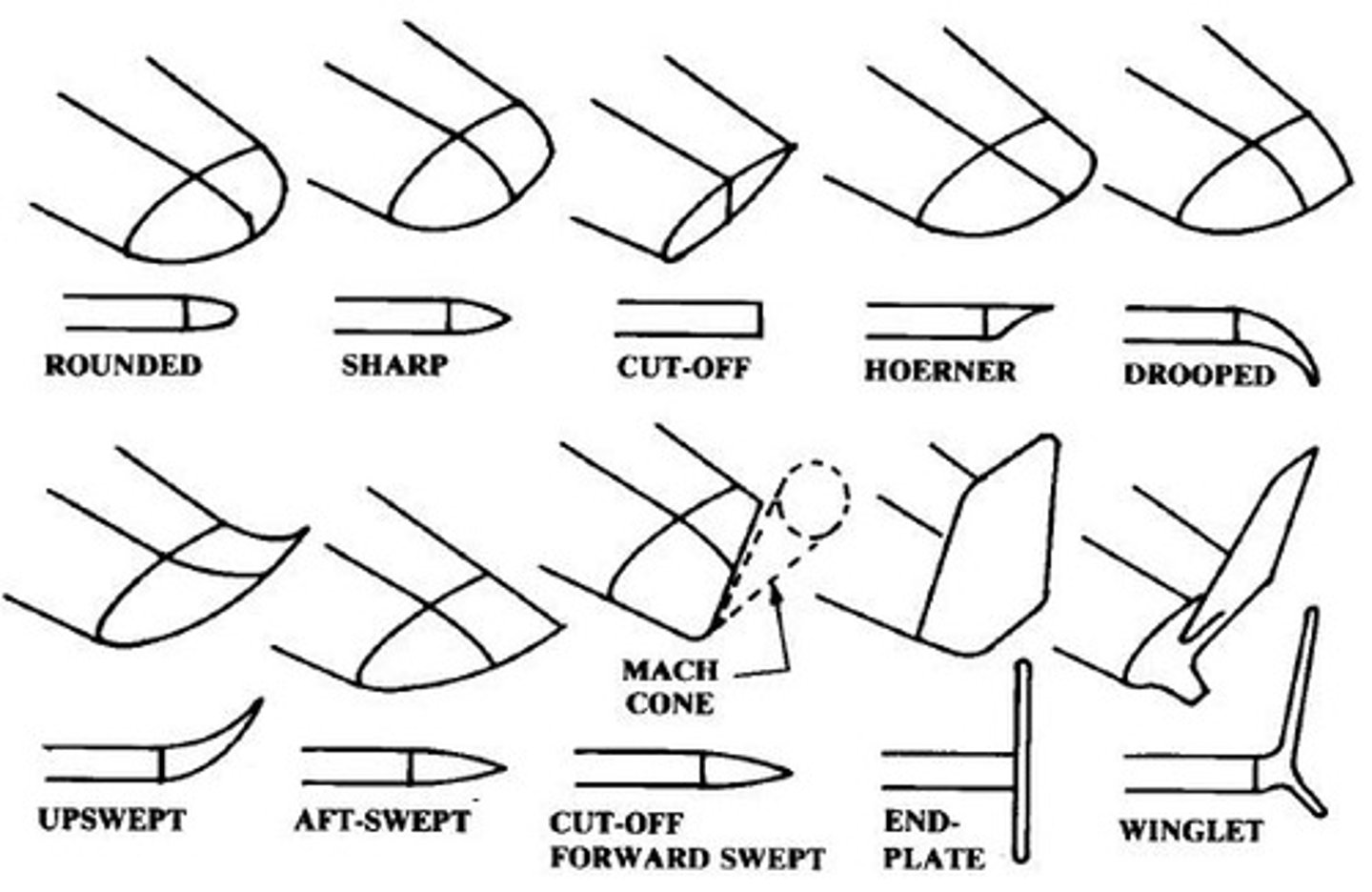
Wing Tips
Design features affecting aerodynamic efficiency.
Stagger
Longitudinal offset between two wings.
Hoerner Tip
Widely used low-drag wingtip design.
Decalage
Relative incidence angle between two wings.
Monoplane
Aircraft with a single main wing.
Bi-Plane
Aircraft with two stacked wings.
Joined Configuration
Wings connected to improve structural integrity.
Cantilever Wing
Wing supported internally without external bracing.
Braced Wing
Wing supported by external struts or wires.
Plain Flap
Hinged rear section of airfoil for lift.
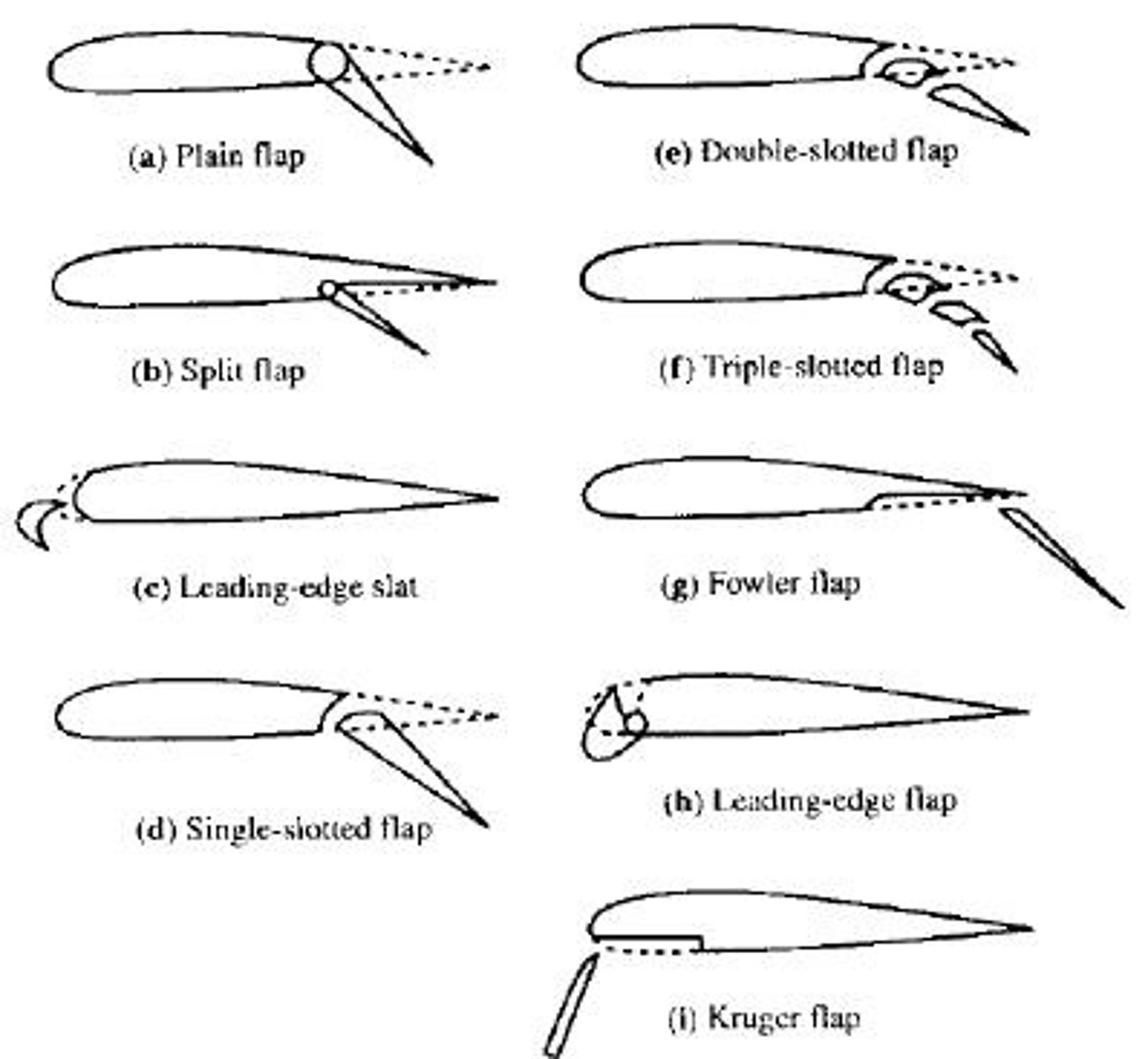
Split Flap
Hinged bottom surface of airfoil for lift.
Krueger Flap
Leading-edge device increasing effective camber.
Leading Edge Slat
Flap at leading edge enhancing lift.
Single-Slotted Flap
Slot allows airflow to stabilize boundary layer.
Double-Slotted Flap
Higher lift coefficient than single-slotted flap.
Fowler Flap
Tracks to increase wing area and lift.
Empennage
Tail structure for stability and control.
T-Tail
Horizontal tail mounted on vertical tail.
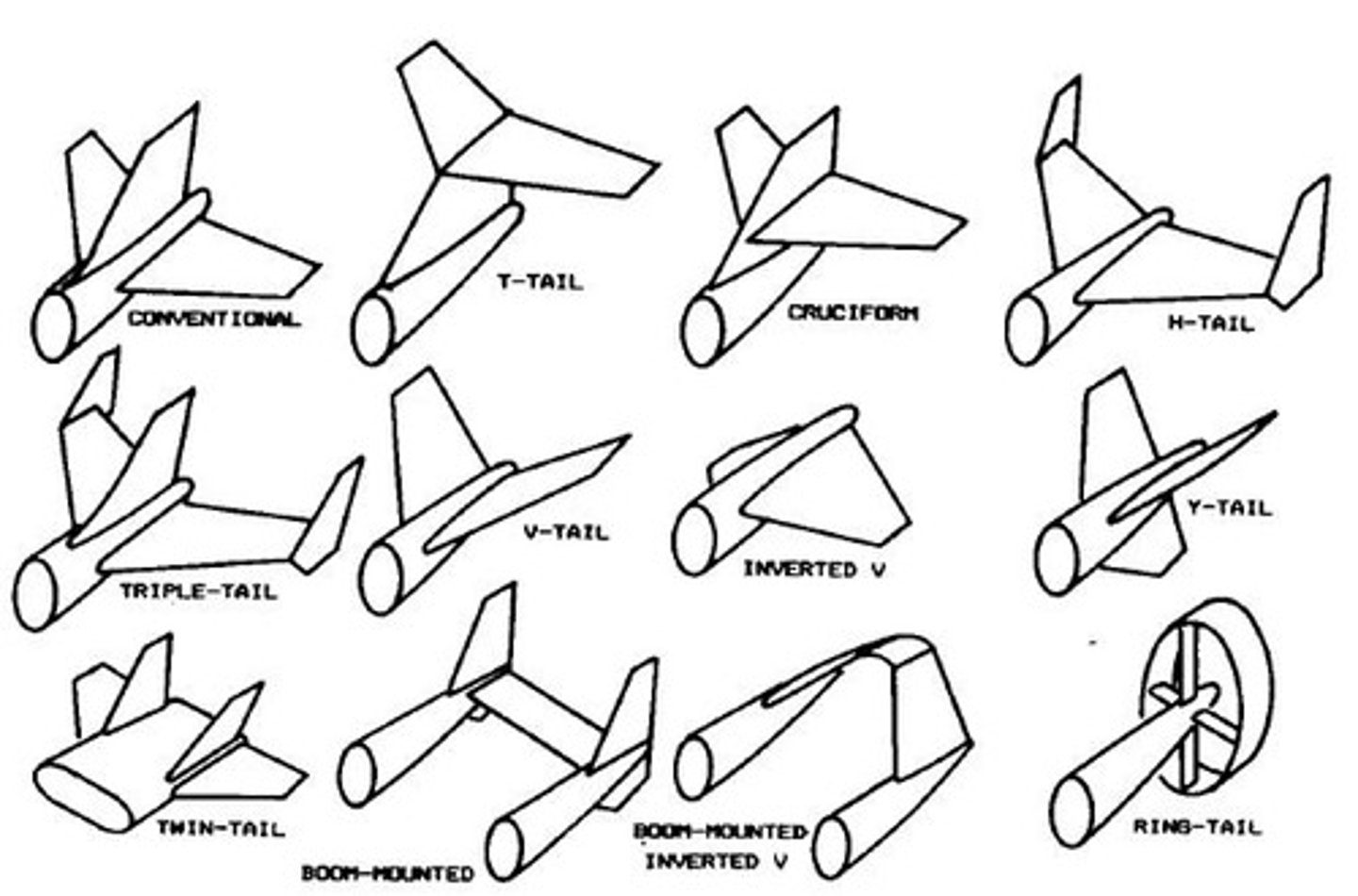
Boom-Mounted Tails
Tails mounted on a boom structure.
V-Tail
Combines vertical and horizontal tail functions.
Inverted V-Tail
Reduces spiraling tendencies in flight.
Control Canard
Forward wing surface for pitch control.
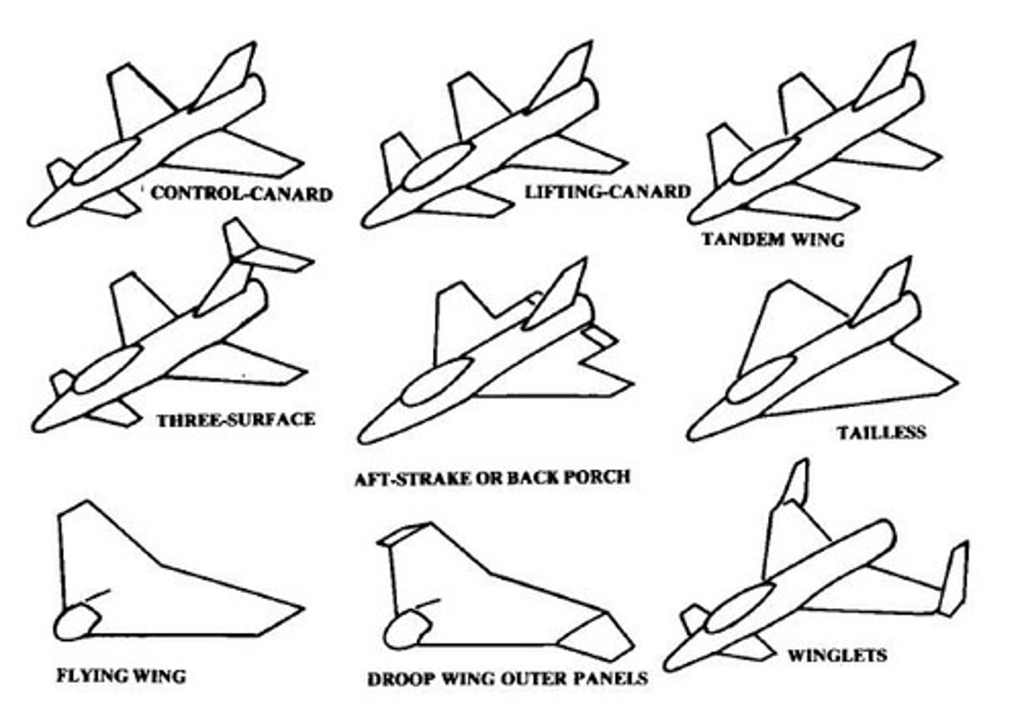
Lifting Canard
Contributes to lift and stability.
Tandem Wing
Two wings positioned one behind the other.
Three Surface Configuration
Includes main wing, canard, and tail.
Back Porch/Aft-Strake
Extension used for pitch control.
Tip Speed
Speed of propeller tips in flight.
Propeller Diameter
Size of propeller affecting performance.
Tractor Configuration
Propeller located forward of the CG.
Pusher Configuration
Propeller located behind the CG.
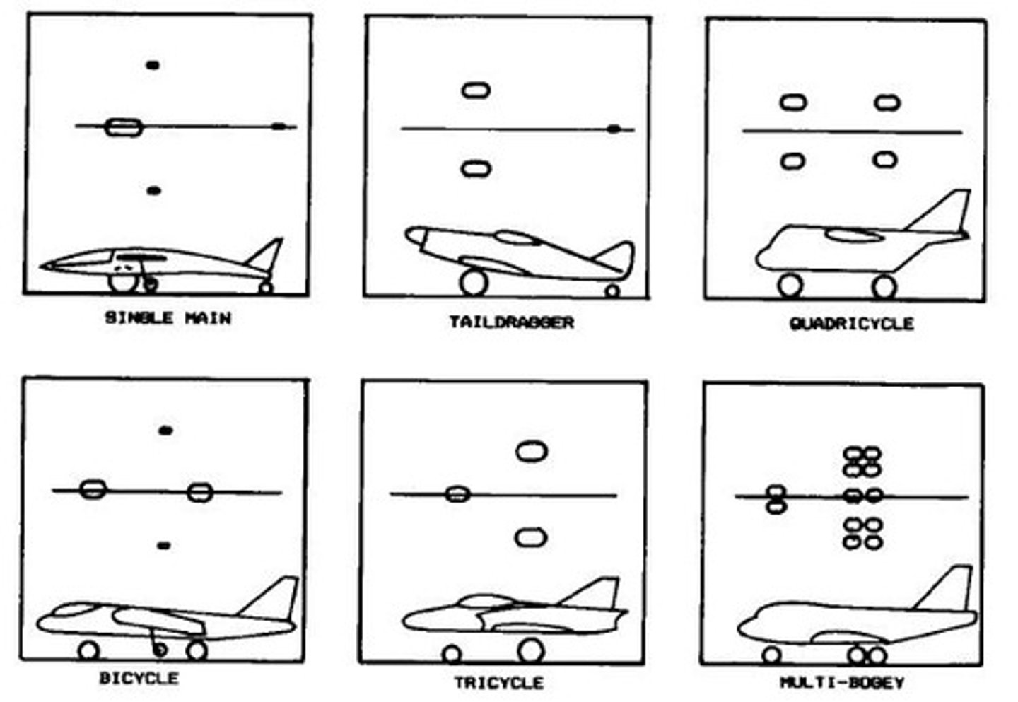
Conventional Landing Gear
Tail-dragger configuration with rear wheel.
Tricycle Landing Gear
Three-wheel configuration for stability.
Maneuver Loads
Air loads during high maneuvering conditions.
Limit Load
Maximum load anticipated in service.
Design Load
Maximum load structure can support.
Gust Loads
Loads experienced during turbulence.