Electron Therapy
1/20
There's no tags or description
Looks like no tags are added yet.
Name | Mastery | Learn | Test | Matching | Spaced |
|---|
No study sessions yet.
21 Terms
What are the different electron interaction types and which are most common?
Elastic collisions with atomic electrons and nuclei.
Inelastic collisions with atomic electrons (ionization and excitation).
Inelastic collisions with atomic nuclei (bremsstrahlung).
in low Z primarily ionization and excitation but in high Z bremm can be significant
what is brem production’s relation to Z and E
Z² E
Stopping power vs restricted stopping power
Stopping power (S) ratios are used to relate the energy loss of electrons per unit path length.
They are frequently used normalized to the density of the material
Restricted mass stopping powers are used to calculate doses to a medium with the restriction that only interactions below a certain cutoff energy are used in calculating dose. The reasoning is that electrons created with higher energy travel away from the site and do not contribute to dose locally.
When exiting the bend magnet, electrons have a very narrow energy window with a most probable energy (average) equal to that specified by the selected energy (e.g. 6, 9, 12 MeV).
By the time the electrons reach the surface of a patient, they have undergone scattering in the foils, collimation system, and air. This broadens the energy window.
At depth in the patient, due to the large amount of scattering occurring, the energy window is significantly broadened.
Electron energy spectrum: at bending mag exit, surface, depth
When exiting the bend magnet, electrons have a very narrow energy window with a most probable energy (average) equal to that specified by the selected energy (e.g. 6, 9, 12 MeV).
By the time the electrons reach the surface of a patient, they have undergone scattering in the foils, collimation system, and air. This broadens the energy window.
At depth in the patient, due to the large amount of scattering occurring, the energy window is significantly broadened.
Energy of an electron beam in terms of practical range

mean energy at the patient’s surface can be related to R50 by
E0(MeV) = 2.33R50
Avg energy at depth
Ez=Eo(1-z/Rp)
What is the therapeutic range and what is the rule of thumb to calculate it
Rt = E/3 and its the 80-90% IDL
Rp rule of thumb
E/2
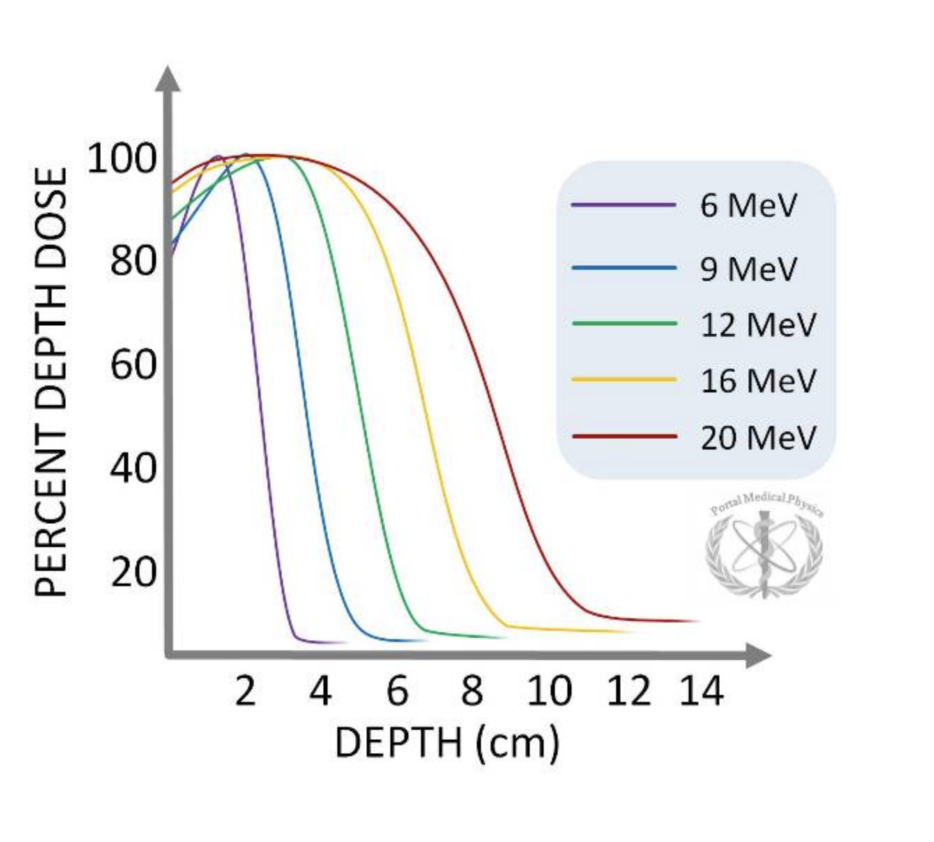
Electron PDD changes with Energy+ draw PDDs for several energies
Surface dose increases with energy.
This is because, at higher energies, scatter is less likely and predominantly forward. Therefore, the surface dose relative to the maximum dose is similar in high energy beams (in low energy beams there is more scatter and larger scattering angles involved causing the dose to build up more rapidly and to a greater degree).
The slope of the falloff decreases with energy.
This is due to the randomness of the electron paths as they travel through the body. At higher energies, they have a longer path length and therefore more opportunity for their energy spectrum to spread out.
Higher energy electron beams have a very large flat plateau that occurs due to the relative lack of buildup in high energy beams.
As the energy of the electron beam increases, the amount of x-ray contamination increases due to the higher likelihood of bremsstrahlung interactions (proportional to energy).
Electron PDD variation with field size
In general smaller field size results in depth of dmax shifter shallower and a decrease in the slope of the falloff.
curves are relatively constant until the field size becomes small enough that the lateral charged particle equilibrium is lost
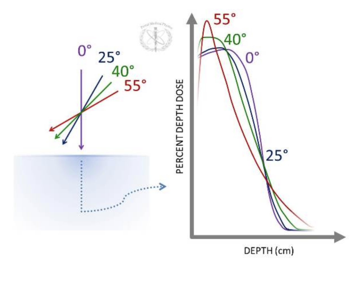
electron PDD variation with angle of incidence and draw effect of 0/40/55 degree incidence
An oblique angle will shift dmax shallower along with the 80% isodose curve depth (effective treatment depth).
Notice that the range appears to increase at greater oblique angles. This is due to electrons side scattering from parts of the beam that have not passed through much water due to the oblique angle.
what do we directly measure with an ion chamber for electrons
PDI - convert to PDD by multiplying by restricted stopping power relationship
WHY
stopping power ratios vary with energy
In a dense medium (water) when an electron interacts it creates ions. Due to the high density of the medium, the created ions are also very dense. These ions screen the incident electron’s electric field from interacting with distant particles and reduce the interaction rate.
In a gas (air) the relatively low density means that the ionization track has a low density of ions, and, therefore, there is negligible screening of distant particles.
When comparing the stopping power ratio of water to air the ratio is no longer constant.
However, using a silicon diode (also a solid) the ratio remains relatively constant and, thus, instant %DD curve.
why are jaw sizes fixed for a given cone
the jaw size is fixed at a constant value. This is due to the huge variation in output with jaw size especially at lower energies (see left figure above) which can vary as much as 200%.
Output is much more stable when the cone size is varied, however (see right figure above) and varies only about 15%.
This large difference is due to the huge amount of scattering surfaces in the LINAC head as compared to the cone.
Isodose curve trends
At low energies, the low dose isodose lines (20,30%) bulge out, but the high dose isodose lines (90,100%) are fairly straight.
At high energies, the low dose isodose line tend to remain straighter but the high dose isodose lines pinch in.
When extended SSDs are used to treat a patient there is more penumbra
uniformity index for electrons
The uniformity index is a way to quantify the amount of penumbra in an electron beam.
It is defined as the ratio of the area of 90% isodose curve to that of the 50% isodose curve.
Values greater than 0.7 are considered acceptable for fields larger than 10x10 cm2.
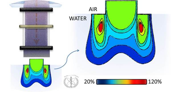
Explain why this happens
The water increases lateral scatter to the surrounding air and leads to hot spots adjacent to it.
The air attenuates the field much less and the isodose curves extend deeper.
A loss of scatter from the air causes a significant pinching in of the isodose curves traversing the water.
The most important thing to remember is that Monte Carlo must be used to calculate around inhomogeneities as the pencil beam algorithms are inadequate.
Virtual source distance
found by taking a series of measurements at various SSD’s.
Suppose you have a standard SSD (usually 100 cm), and you wish to know the output for another SSD then the inverse square relationship using the VSD would be:

Q0 - is the chamber reading at the standard SSD.
Qg - is the chamber reading at an extended SSD with gap g.
VSD - is the virtual source distance.
dmax - is the depth of maximum dose for the electron energy of interest.
g - is the gap and is defined as the difference between the standard SSD and the extended SSD (for instance SSD’s of 100 cm and 110 cm would have a gap of 10 cm).
Can rearrange so that it is CSD = 1/f -dmax
thickness of a shield rule of thumb
The thickness of shielding required can be quickly approximated using the practical range in water (MeV/2) and then taking the ratio of the density of the shielding material to water.
For instance lead has a density of 11.34 g/cm3. Therefore, you require about 1/11th the amount of lead as a water equivalent shield.
So, for a 12 MeV beam with a practical range of 6 cm in water we need a lead shield of about 5 mm.
Explain how TSE treatments are set up
TSE treatments are given to patients with systemic skin diseases such as Mycosis Fungoides.
Treatments are usually delivered at extended SSDs using a degrader and 2 fields.
A degrader is placed in the beam to scatter the electrons and reduce their energy.
Each field is usually separated by about 20 degrees and scatter in the air and degrader yields a homogeneous dose distribution on the patient within +/-8%.