Treatment Techniques (Definitions and Terminology)
 Call Kai
 Learn
Learn Practice Test
 Spaced Repetition
 Match
Match Flashcards
 Knowt Play
1/84

There's no tags or description
Looks like no tags are added yet.
Name | Mastery | Learn | Test | Matching | Spaced | Call with Kai | Chat |
|---|
No analytics yet
Send a link to your students to track their progress
85 Terms
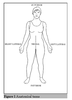
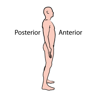
Towards the head
superior
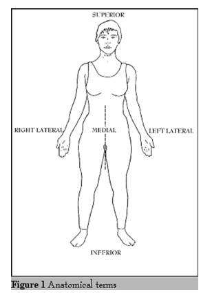
away from the head
inferior
towards to the front
anterior
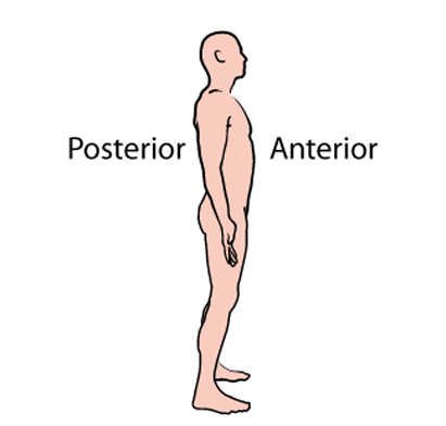
towards the back
posterior
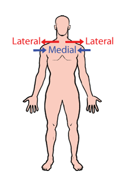
nearer to the front
medial
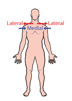
farther from the midline
lateral
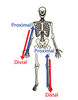
nearer to the point of origin/attachment
proximal

farther from the point of origin/attachment
distal
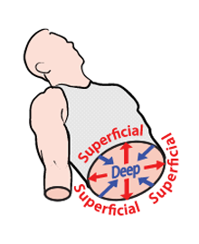
on/near the surface
superficial
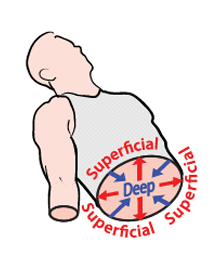
away from the surface
deep
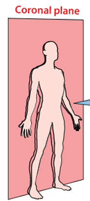
Perpendicular to the sagittal plane
Divides the body into anterior and posterior sections
Coronal
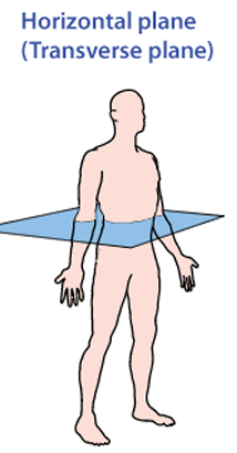
Perpendicular to the midsagittal, parasagittal, and coronal planes
Divides the body into superior or inferior parts
Transverse
Divides the body into right and left parts
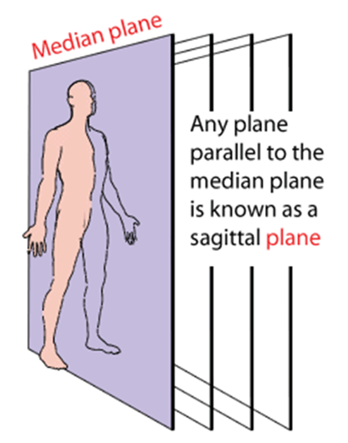
sagittal plane
Midsagittal (Median Sagittal) - Plane divides the body into equal right and left halves
Parasagittal Plane - Divides the body into unequal right and left portions (parallel to the midsagittal plane)
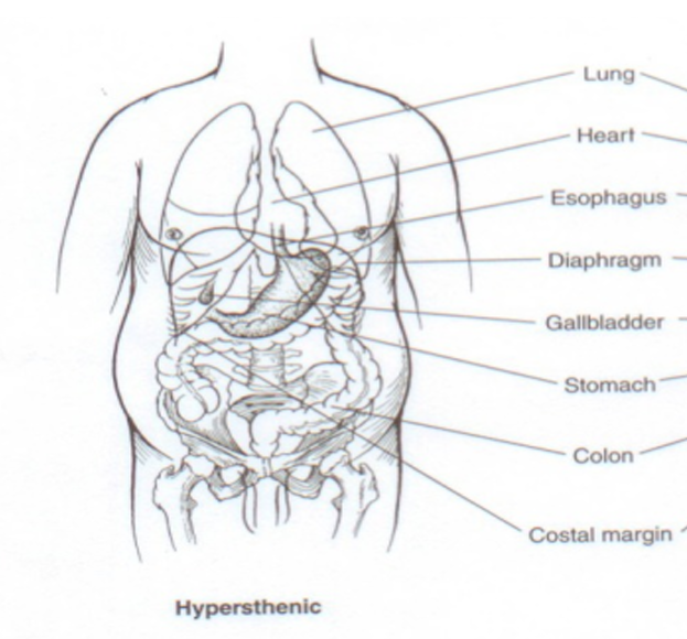
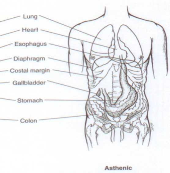
Prevalence: ~5% of the population.
Build: Short, wide trunk; large body weight; small pelvic cavity.
Stomach position: High, wide, and horizontal.
Other features: Heavy skeletal framework; large alimentary tract.
Clinical note: May require cross-positioning in chest X-rays to capture the entire chest
Hypersthenic
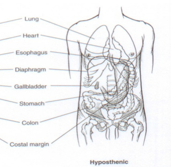
Prevalence: ~35% of the population.
Build: Below average; more slender and elongated.
Stomach position: Slightly lower J-shaped; more medial placement.
Other features: Abdominal cavity size between sthenic and asthenic; similar organ positioning to sthenic but slightly lower
Hyposthenic
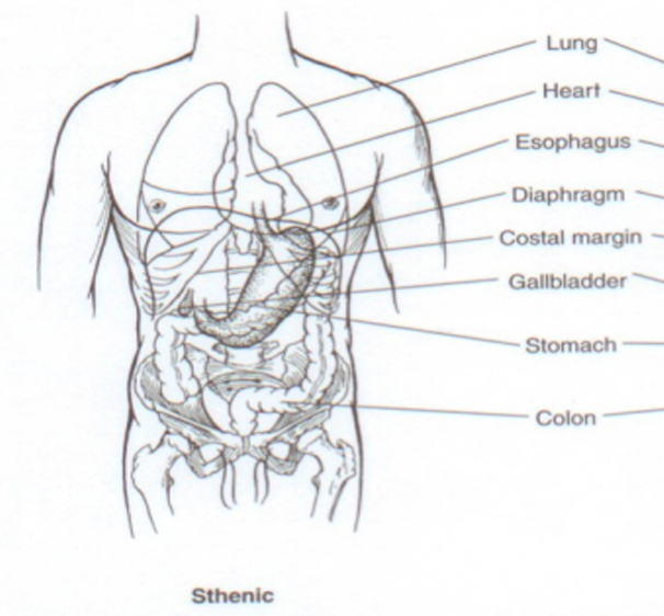
Prevalence: ~50% of the population (most common).
Build: Average physique; heavy skeletal structure; well-developed musculature.
Stomach position: High, J-shaped, in the left upper quadrant.
Other features: Moderate thorax length and depth; moderate lung and heart size.
Clinical note: Serves as the standard reference for normal anatomical measurements
Sthenic
Prevalence: ~10% of the population.
Build: Very slender; light body weight; long abdominal cavity.
Stomach position: Low and elongated; close to the vertebral column.
Other features: Light skeletal framework; pelvis with greater capacity.
Clinical note: Heart may appear “hanging” in the thorax; requires special imaging positioning
Asthenic
A medical specialty that uses ionizing radiation to treat cancer and some benign diseases
Standard equipment – Linear accelerator
Radiation Therapy
Process of determining the patient treatment position, the volume to be treated and the normal structures in or surrounding that volume
Standard equipment- CT scanner
Simulation (treatment planning procedure)
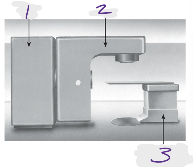
1
Drive stand
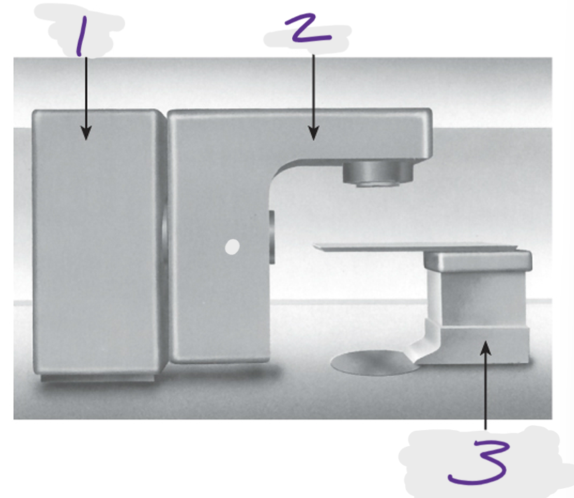
2
Gantry
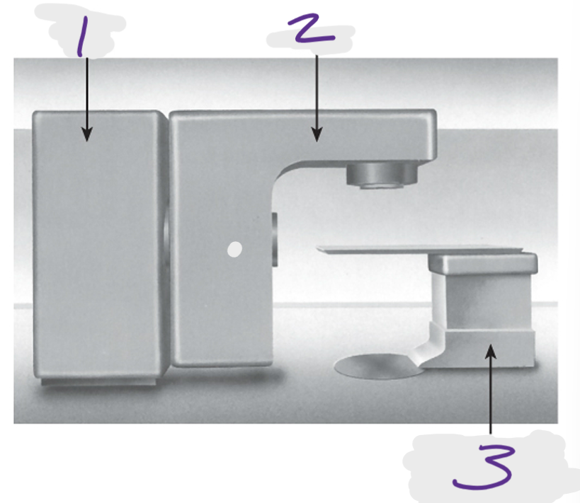
3
Patient support assembly (treatment couch)
PSA
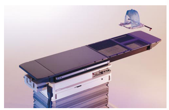
patient support assembly, table or couch
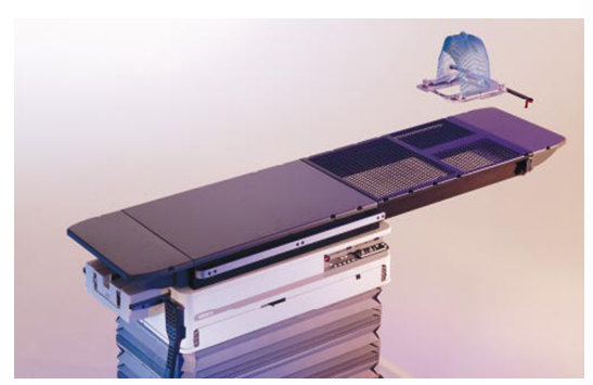
TT
table top distance: the distance from the table top to the isocenter
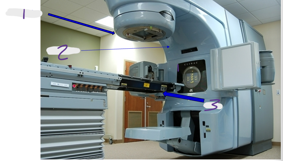
1
collimator
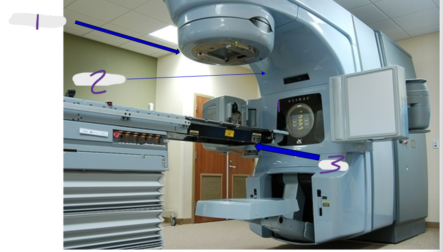
2
gantry (360 rotation)
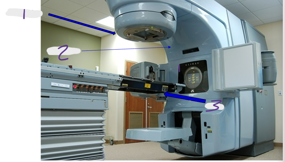
3
table
hand pendant
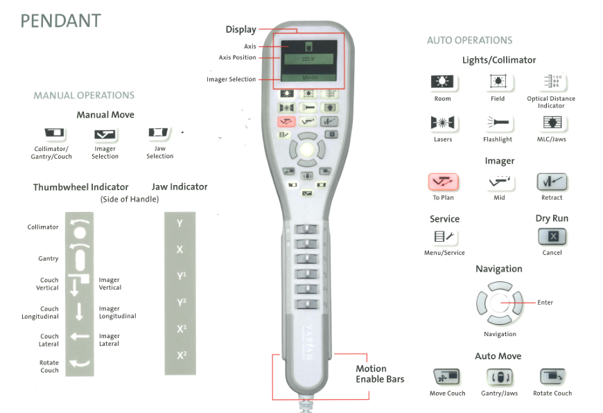
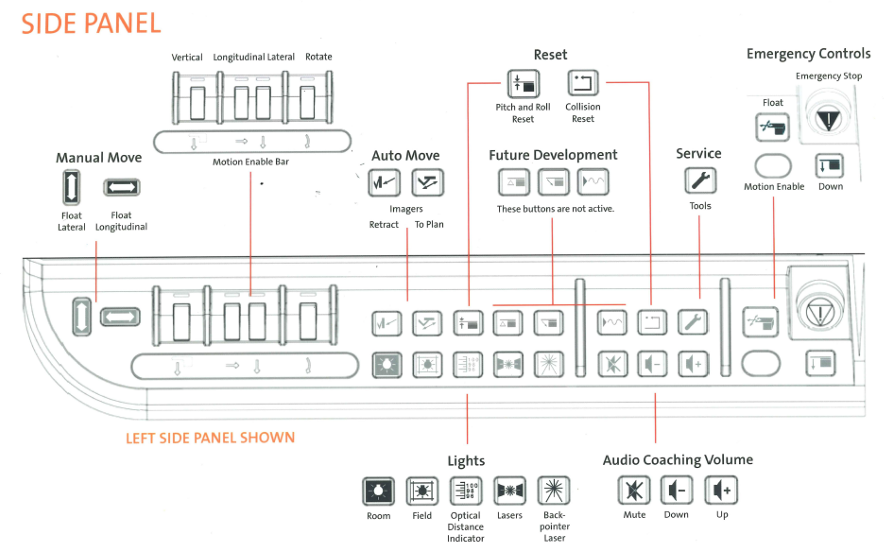
table controls
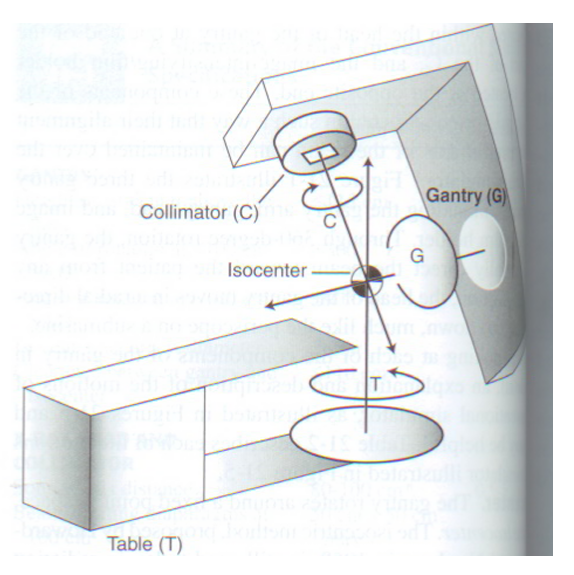
Point of intersection of the three axes of rotation – (gantry, collimator, couch) of the treatment unit
Isocenter
The treatment unit isocenter is static
It is a set distance of 100 cm from the treatment source
treatment approach where the treatment unit’s isocenter is placed at a reference point within the patient, typically within or near the target volume
Isocentric Treatment
The physical size set of the treatment field at the isocenter
field size
Defined at the machine’s isocenter (a distance of 100 cm from source)
Represented by W x L
Accomplished by the jaws inside the collimator
X and Y are the upper and lower jaws
Asymmetric jaws with modern technology •
Jaw moves independently
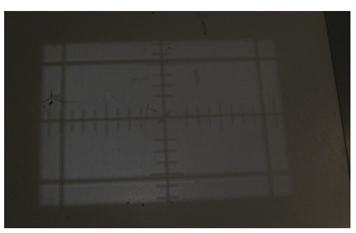
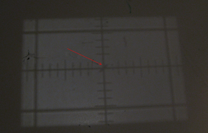
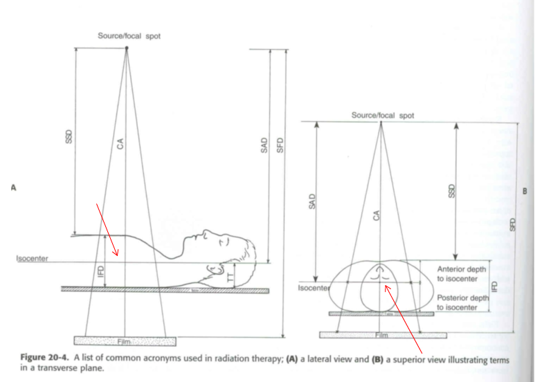
The red arrow is pointing to the ______ of the beam.
central axis
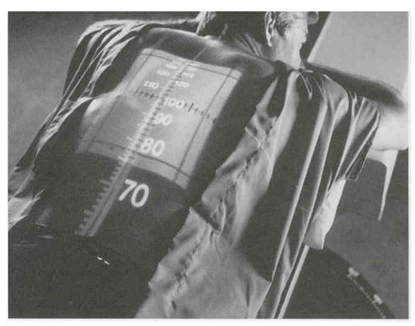
device mounted on or near the collimator head that projects a scale onto the patient’s skin
number projected at the central axis is the distance from the source to the skin surface (SSD*)
ODI – Optical Distance Indicator
____ project via a red or green light used in the simulation and treatment process
____ project in the transverse, sagittal and coronal planes
____ assist in positioning by providing external reference points in relation to the position of the isocenter
Lasers
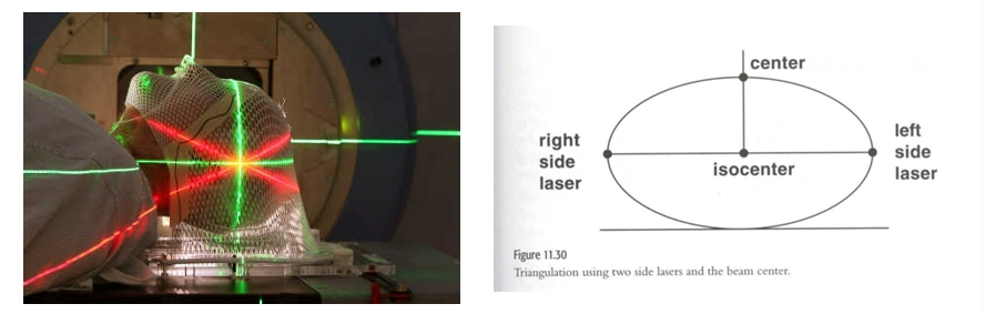
Patient/Table/Source/Distance Relationship
The redlines on this diagram demonstrate the isocenter of this patient.
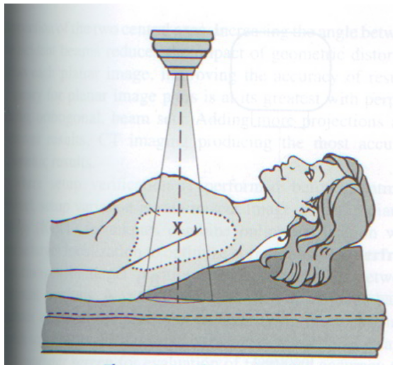
the distance beneath the skin surface where the prescribed dose will be delivered
depth
measure of patient’s thickness from the point of beam entry to beam exit
Patient Separation
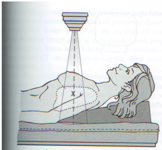
the distance from the source or target of the treatment machine to the surface of the patient (skin)
Source-Skin Distance (SSD)
Also TSD (target-skin distance)
Measured with the ODI
Where the field size is defined on the surface
The field size set on the collimator is the same as measured on the skin surface of the patient
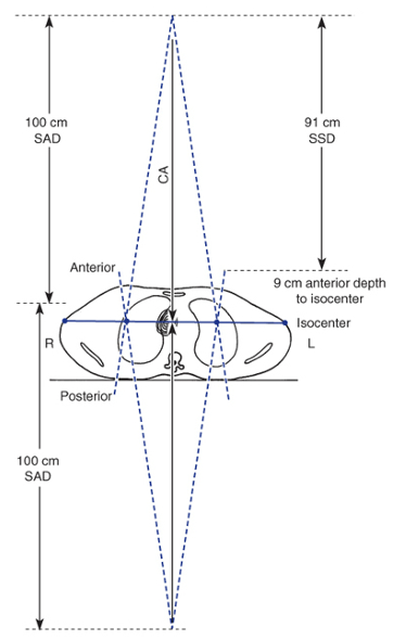
the distance from the source of photons to the isocenter of the treatment machine
Source-Axis Distance (SAD)
Also, target-axis distance
The SAD for modern linear accelerators is 100cm
the field size is defined is inside the patient at the isocenter distance
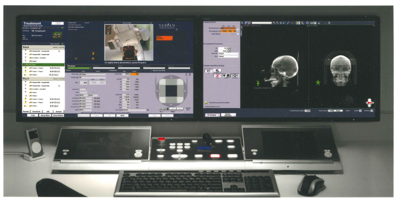
control console
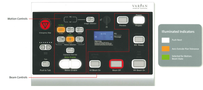
control console
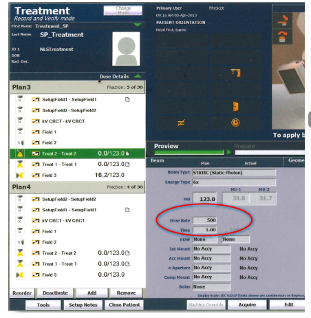
Unit of output measure used for linear accelerators
Monitor Units (MU)
MU is the length of time a unit is physically on to deliver a prescribed dose. The MU is the treatment “time” for a linear accelerator.
Linear accelerators are calibrated so that 1 MU delivers 1cGy for a standard source to calibration point
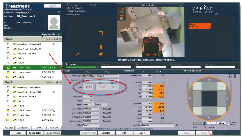
Also known as output
The amount of radiation exposure produced by a treatment machine or source specified at a reference field size and distance
Changing the field size, distance or attenuating medium will change the ____.
____ increases with increased field size. (when there is an increase in field size, the scatter is increased which adds to the output.)
Dose Rate (cGy/MU)
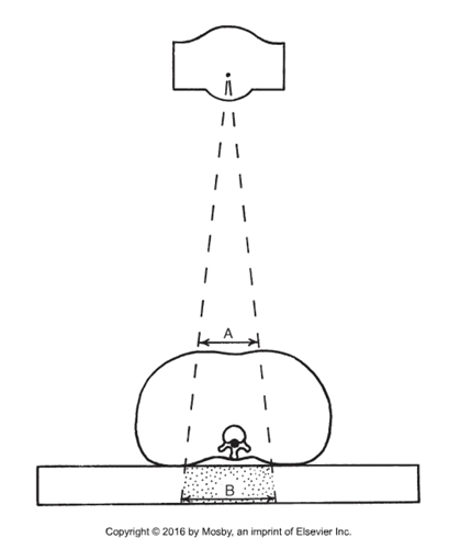
Spreading out of the beam of radiation.
More tissue is exposed as the beam exits the patient than at the anterior skin surface.
divergence
The dose prescribed by the physician at a particular depth within the patient that will provide adequate coverage of the tumor.
Tumor Dose (TD)
Dose delivered to Dmax depth through a single treatment field
Also known as applied dose, or Dmax dose
Given Dose (GD)
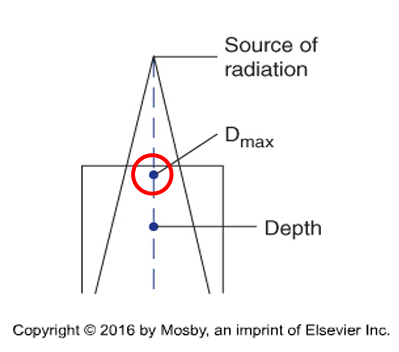
The depth of maximum buildup, in which 100% of the dose is deposited beneath the skin.
The depth at with electronic equilibrium occurs for photon beams
The depth of maximum absorbed dose and ionization in a single treatment field for photons.
Dmax depth
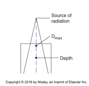
The ratio expressed as a percentage, of the absorbed dose at a given depth to the absorbed dose at a fixed reference depth, usually Dmax.
Percent Depth Dose (PDD)
PDD= Absorbed Dose at Depth / Absorbed Dose at Dmax
documentation of treatment portals through radiographic images or electronic portal images
Portal verification (port film, PF)
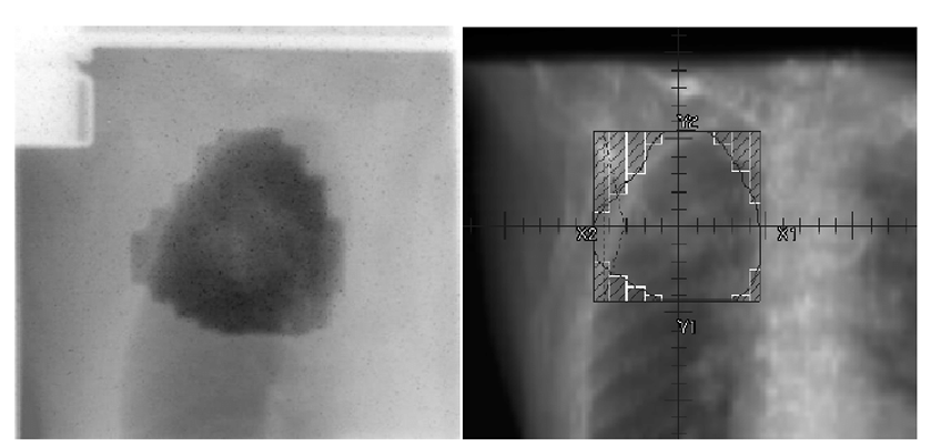
Planar or CT images confirming treatment setup
Completes treatment record and verification image communication between therapist and Rad Onc
Documents treatment localization reproduction
Images are acquired with the patient in the treatment position and compared with reference images from the treatment plan and initial simulation.
Verification Imaging
Blocked field size
The equivalent rectangular field dimensions of the open or treated area within the collimator field dimensions.
It is the actual area treated
Effective Field Size
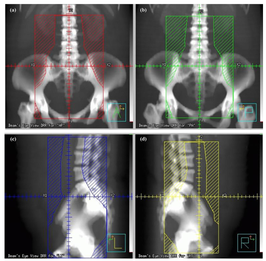
Images reconstructed from CT data that represent the patient’s anatomy and defined volumes from the perspective of the treatment beam.
Viewing the patient anatomy from the perspective of the treatment field
Helps to ensure the orientation of the patient and the treatment machine are correct
Useful in identifying best gantry, collimator, couch angles
Verifies geometric coverage of target volume
Shielding and MLC design
Beam eye view – BEV
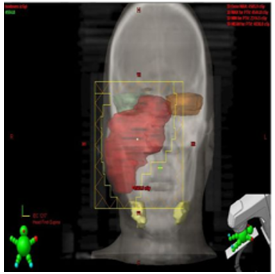
area of known and presumed tumors
Target Volume
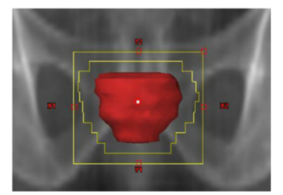
process by which does delivery is optimized for a given patient and clinical situation
Treatment planning
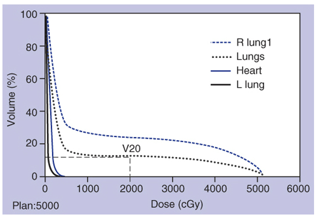
a graph that evaluates and displays how much dose is delivered to a target or surrounding critical structures
Dose Volume Histogram (DVH)
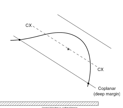
two radiation fields configured so that the beam edges lie on the same geometric plane
Used to align field edges so the dose matches more evenly at the junction/margin
The central rays are not necessarily parallel opposed
Coplanar
fields arranged on different planes, often requiring couch or gantry angle changes
Non-coplanar
When radiation beams lie in the same plane, this is ____.
When one beam lies in a plane and another beam passes through that same plane, this is ____.
coplanar
noncoplanar
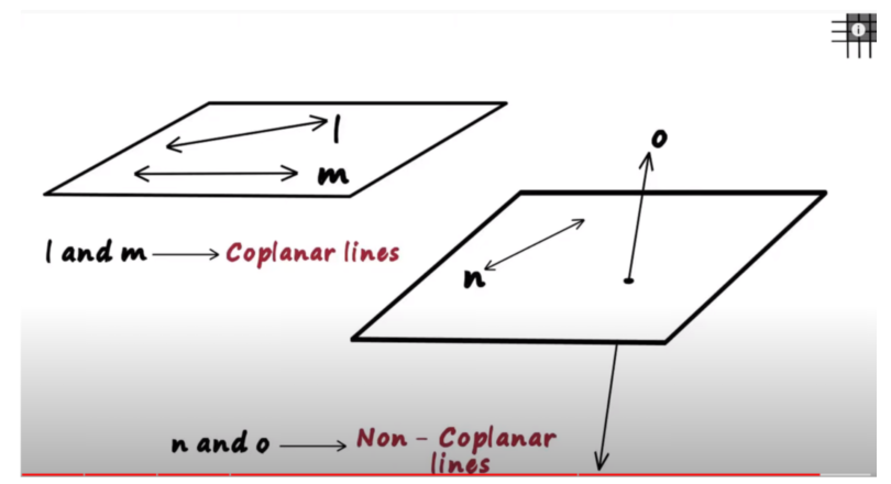
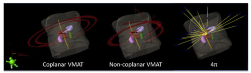
Coplanar and Non-coplanar
*VMAT: Volumetric Modulated Arc Therapy
the measure of the angle between the central rays of 2 intersecting treatment beams
Hinge angle
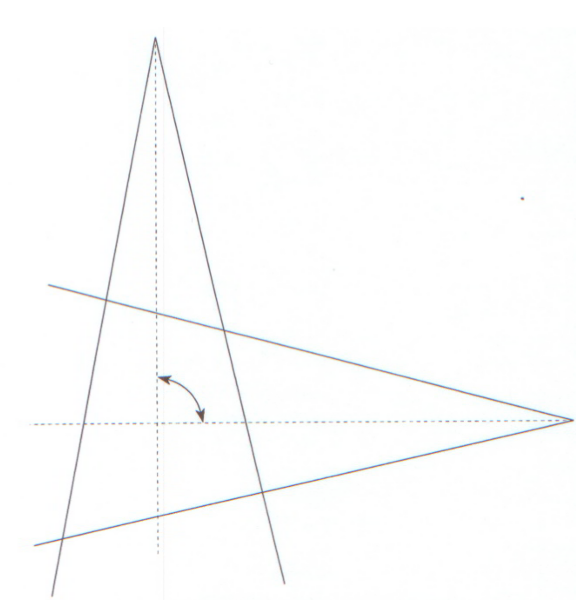
two images taken at 90 degrees apart
used for setup verification and treatment planning
used to define the location and relationship of various anatomic structures relative to the fields isocenter
Orthogonal Films
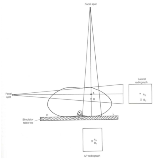
Dose to any tumor or mass is limited by its surrounding structures and tissues.
Tolerance doses were established for normal tissues in terms of total dose delivered by a standard fractionation schedule that caused minimal (5%) or maximal (50%) complication rate within 5 years
NTTD is affected by 2 factors:
Volume irradiated
Organs can tolerate more dose if the volume of the organ being irradiated is small
As volume of organ increases the tolerance dose for the whole organ decreases
Fractionation
Normal tissue tolerance doses (NTTD)
____ is the dose that would likely cause 5% of an exposed population to produce an adverse late effect in 5 years following exposure.
Relates to the minimum dose it would take to cause injury in 5% of patients within 5 years
OR
Total dose delivered by a normal standard fractionation that causes (5%) minimal complication rate within 5 years = ____
TD 5/5
____ is the dose that would likely cause 50% of an exposed population to produce an adverse late effect in 5 years following exposure.
relates to the maximum dose it would take to cause stated injury in 50% of patients within 5 years
OR
Total dose delivered by a normal standard fractionation that causes (50%) maximum complication rate within 5 years = ____
TD 50/5
The total dose for Radiation treatments is divided into daily fractions over an extended period of time
(individual treatment dose)
Fractionation
time period during which the total treatment dose will be given (number of treatments or days)
Type of tumor and the tolerance of normal tissue in the treatment field determine the total dose, size, number of fractions, and treatment duration (protraction)
As the daily fraction (daily dose) increases
Cell killing increases
The cells ability to repair sublethal damage decreases • results in a decrease in the radiation tolerance of the normal tissues.
Protraction
Common Abbreviations
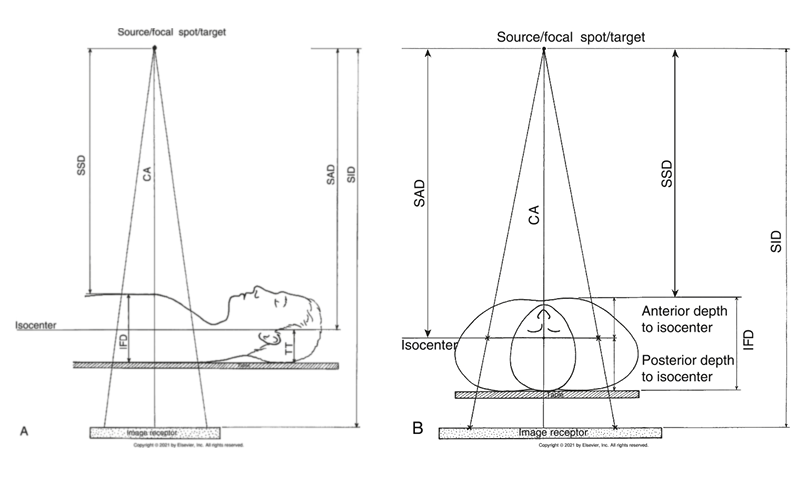
TSD/SSD
TID/SID
TOD
target/source to skin distance
target/source to image receptor distance
target to object distance
Simulation - review of some terms
Directional Acronyms
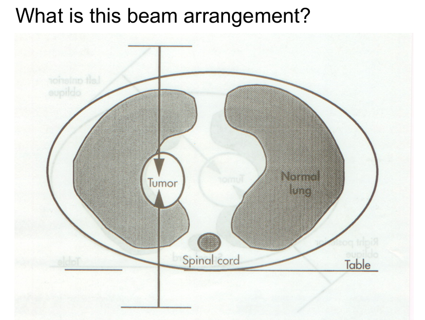
AP
PA
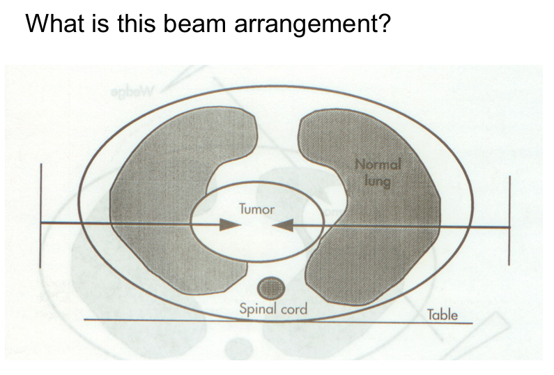
RT
LT
POP
Tangential (tangents, “tangs”)
anterior-posterior
CA is directed from anterior to posterior
posterior-anterior
CA is directed from posterior to anterior
Right
Left
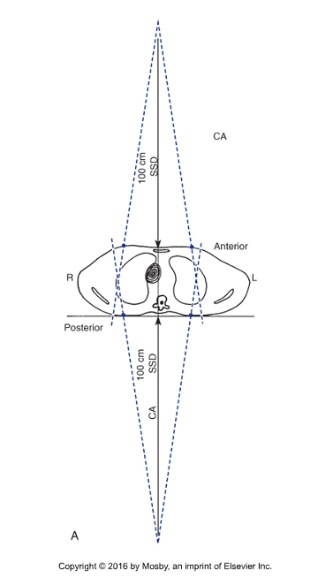
parallel opposed – two treatment fields planned 180 degrees apart
can enter the patient from any two directions relative to the patient (i.e., rt/lt laterals, AP/PA, and anterior and posterior obliques)
opposing fields which flash off the surface of the patient
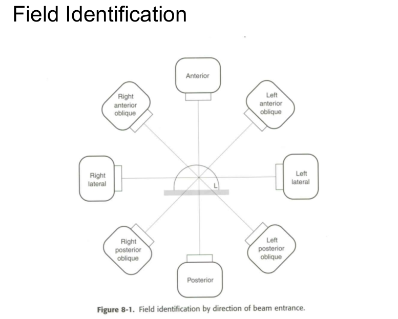
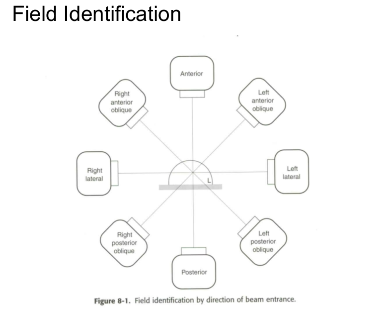
Directional Acronyms
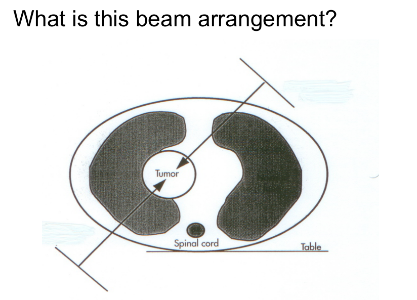
LAO
LPO
RAO
RPO
left anterior oblique – the central axis is directed from the left anterior aspect of the patient
left posterior oblique – the central axis is directed from the left posterior aspect of the patient
right anterior oblique – the central axis is directed from the right anterior aspect of the patient
right posterior oblique – the central axis is directed from the right posterior aspect of the patient
AP/PA
LAO/RPO
RT/LT Laterals
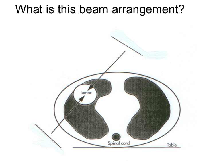
LAO/RPO
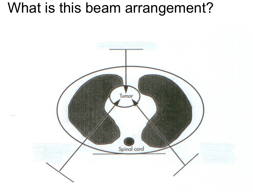
AP, RPO/LPO
____ is a line perpendicular to the cross-section of the simulation or treatment field. It is the only imaginary line emanating from the source (focal spot) of radiation that is not divergent.
CA (CAX) - Central Axis
____ is a measurement used for treatment planning purposes to determine the thickness of a body part from entrance point to exit point, often measured along the CA.
IFD - Intrafield distance (also called separation)
Any process used to capture the X-ray, magnetic resonance image (MRI), or sonographic information, including film, electronic, or digitally reconstructed radiograph (DRR).
Image
Point in space where radiation beams intersect from any of the 360-degree gantry angles. It is similar to the spokes of a bicycle wheel intersecting at the axle
Introcenter
____ is the distance from the source of radiation to the axis of the radiation beam or isocenter (also referred to as TAD [target-axis distance]).
SAD - Source-axis distance
____ is the distance from the target of radiation to the imager
TID - Target imager (receptor) distance
____ is the distance from the source of radiation to the skin surface of the patient (also referred to as TSD [target-source distance])
SSD - Source skin distance
Geometric point or area where the radiation beam emerges and fans out or diverges as it moves farther from the source, target, or focal spot.
Virtual/focal spot
Common abbreviations
DRR
MLC
V & R
Digitally reconstructed radiograph
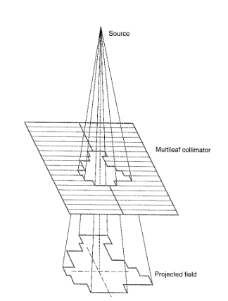
Multileaf collimator
Verify and Record system