ME 115 - Week 8
 Call Kai
 Learn
Learn Practice Test
 Spaced Repetition
 Match
Match Flashcards
 Knowt Play
1/17

Earn XP
Description and Tags
Creep fracture
Name | Mastery | Learn | Test | Matching | Spaced | Call with Kai | Chat |
|---|
No analytics yet
Send a link to your students to track their progress
18 Terms
Fractography
Looking at fracture surface under a microscope.
Overloading
Loading a structure far above it’s ultimate tensile strength.
Transgranular Fracture
This is the most common fracture and it simply means that the rupture goes through the grains, not along the grain boundaries.
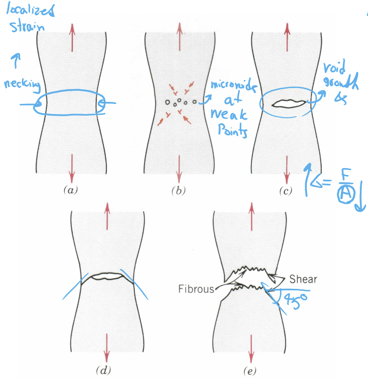
Ductile Fracture
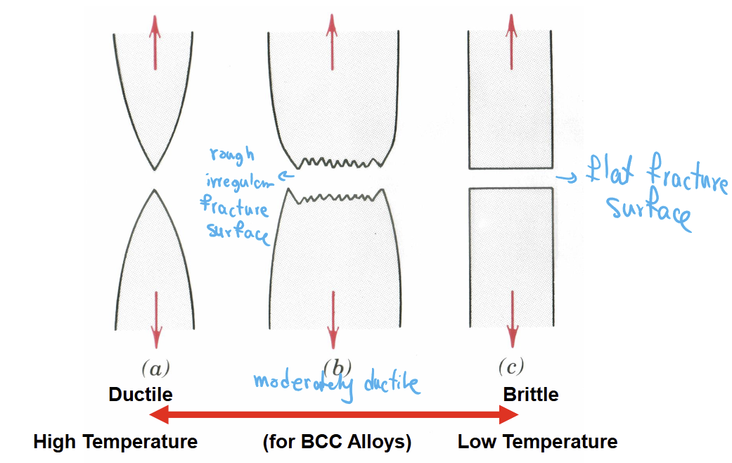
Slow, with plastic deformation, material absorbs more energy, crack growth is typically slow and controlled, fracture surface is rough and textured (dimples). This is the result of overloading.
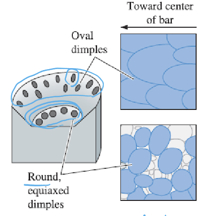
Columnar
Ovular; voids stretched out in one direction more than the others.
Equiaxed
Spherical; voids stretched out roughly equally in all directions.
Nucleation
Initial void growth stage in ductile failure.
Surface Dimples
These are characteristic of ductile failure and form through the nucleation, growth, and coalescence of micro-voids. Dimples near the center of the fracture surface tend to be more equiaxed due to the triaxial stress state, while dimples formed on the shear lip of the surface tend to be columnar due to greater shear deformation.
Brittle Fracture
Fast with little to no plastic deformation, low absorbed energy, fracture surface is typically flat and shiny.
Brittle vs. Ductile Fracture
Ductile: Fracture surface is dimpled and fibrous
Brittle: Fracture surface has flat facets with jagged edges
Evidence of Fracture Direction
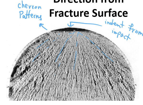
With brittle fractures, you can see if the break was caused by an impact or flaw since there will be a chevron or “blast” pattern in the fracture surface emanating from the origin of the rupture. This could be caused by impact, flaw, or corrosion.
The Chevron pattern forms as the crack propagates from the origin at different levels.
Intergranular Fracture
It indicates the metal broke apart at the grain boundaries, i.e.: the grain boundaries were weak (could be due to unwanted impurities, incorrect heat treatment, corrosion attack, etc.)
Creep
Slow deformation under constant load, and high temperature (T > 0.4 Tmelting). The stress is less than yield strength at that temp.
Diffusion
At a high temp, atoms have enough energy to move through the crystal lattice. This atomic motion allows for change in shape and can move the end of a dislocations end plane so the elevation of the dislocation changes causing dislocation climb.
Causes of Creep
Diffusion, dislocation glide or climb, grain boundary sliding. These all result in the formation of voids and cracks which lead to failure.
Void Creation During Creep
Voids result in a reduction in cross-sectional area of the material. This puts more stress on the voids which reduces the effective load bearing area and this self-accelerates rupture.
Creep cavities form along GBs.
Creep Failure
Does not mean that the material has fully ruptured yet; the material has been damaged/deformed enough that it can no longer perform its intended function, often eventually leading to rupture.
Creep Test
Apply constant stress and constant high temps to a material until rupture. For ductile materials, this will be a tensile test. But for brittle materials it’ll be a compressive test to avoid premature fracture.
Plot strain vs. time → 3 stages of creep