(2) Chapter 1: Getting Started with Cisco Packet Tracer
 Call Kai
 Learn
Learn Practice Test
 Spaced Repetition
 Match
Match Flashcards
 Knowt Play
1/29

There's no tags or description
Looks like no tags are added yet.
Name | Mastery | Learn | Test | Matching | Spaced | Call with Kai | Chat |
|---|
No analytics yet
Send a link to your students to track their progress
30 Terms
Cisco Packet Tracer
A simulator, as the name suggests, simulates network devices and their environment.
LAN
Its protocols of this technology are:

Switching
Its protocols of this technology are:

TCP/IP
Its protocols of this technology are:

Routing
Its protocols of this technology are:

WAN
Its protocols of this technology are:

Security
Its protocols of this technology are:

QoS
Its protocols of this technology are:

Miscellaneous
Its protocols of this technology are:

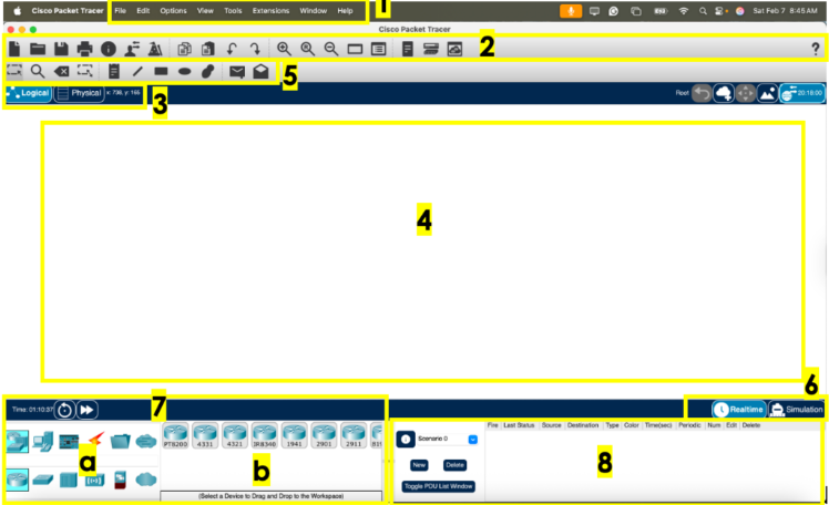
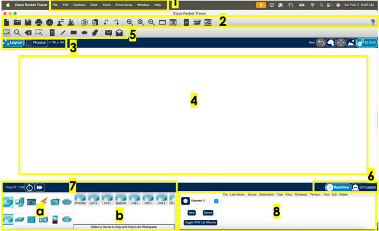
Packet Tracer Interface
ivided into several components similar to a photo editor.
Menu Bar
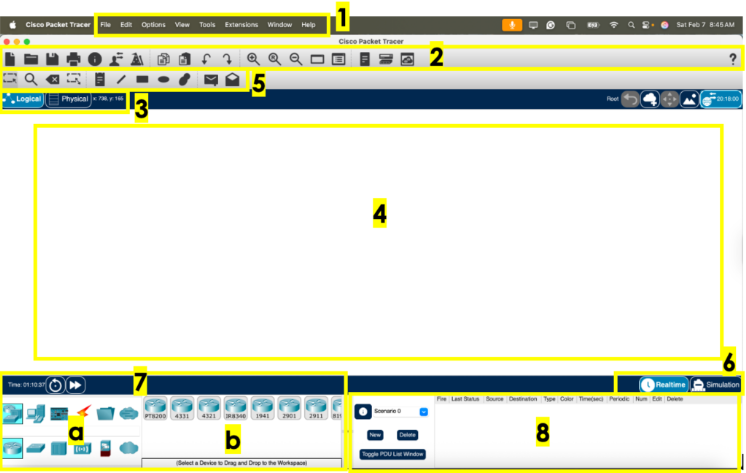
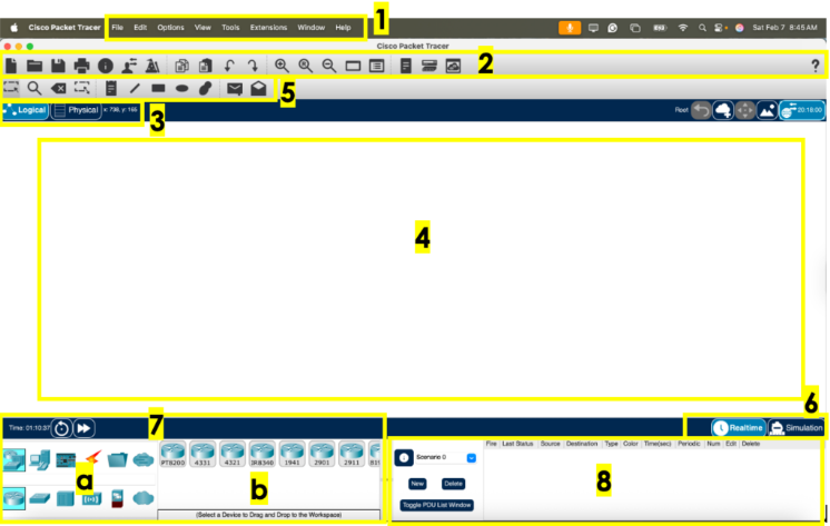
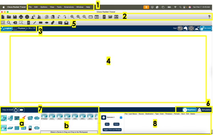
It refers to the number 1 in the Packet Tracer layout diagram.
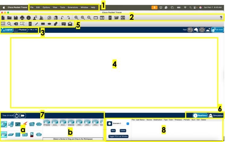
Main Toolbar
It refers to the number 2 in the Packet Tracer layout diagram.
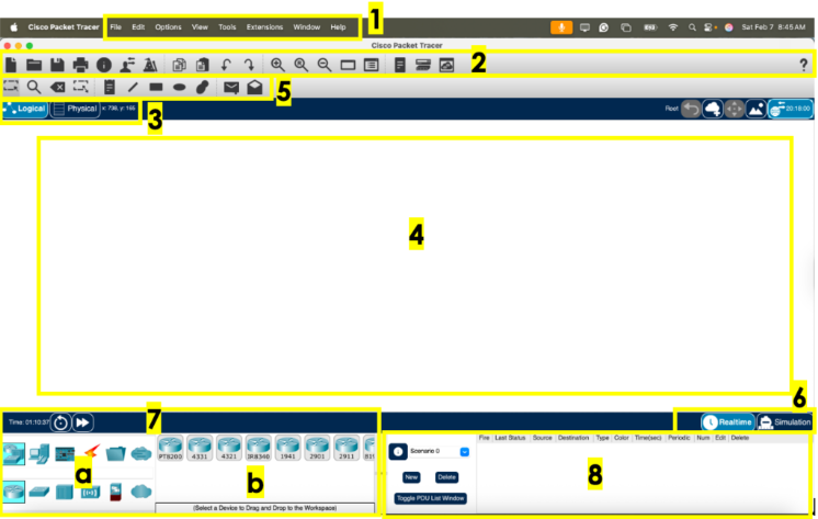
Logical/Physical workspace tabs
It refers to the number 3 in the Packet Tracer layout diagram.
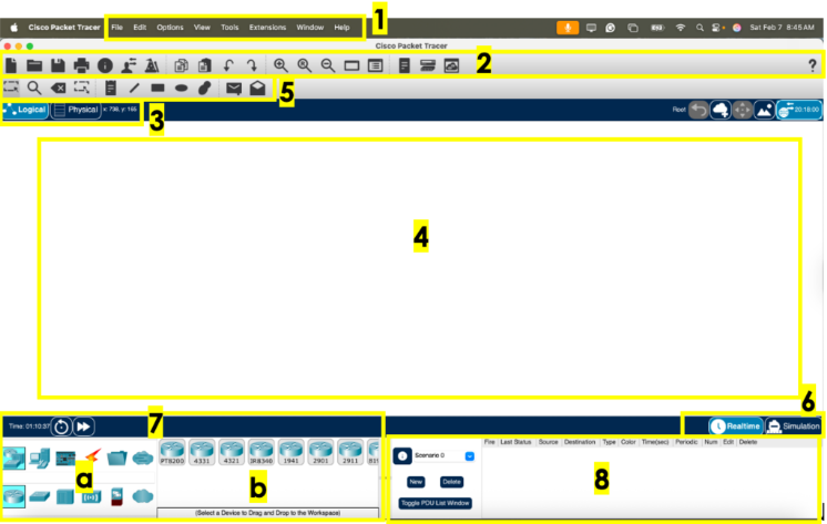
Workspace
It refers to the number 4 in the Packet Tracer layout diagram.
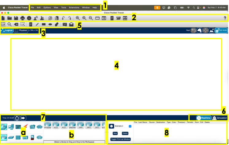
Common tools bar
It refers to the number 5 in the Packet Tracer layout diagram.
Realtime/Simulation tabs
It refers to the number 6 in the Packet Tracer layout diagram.
Network Component Box
It refers to the number 7 in the Packet Tracer layout diagram.
Device-type selection box
It refers to the number 7a in the Packet Tracer layout diagram.
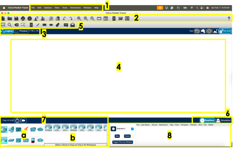
Device-specific selection box
It refers to the number 7b in the Packet Tracer layout diagram.
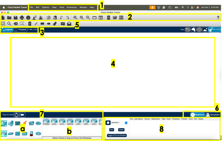
User-created packet box
It refers to the number 8 in the Packet Tracer layout diagram.
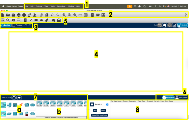
Menu bar
This is a common menu found in all software applications; it is used to open, save, print, change preferences, and so on. Area 1.
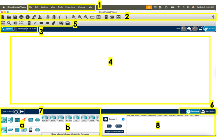
Main toolbar
This bar provides shortcut icons to menu options that are commonly accessed, such as open, save, zoom, undo, and redo, and on the right-hand side is an icon for entering network information for the current network. Area 2.
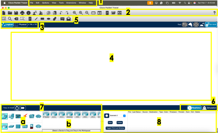
Logical/Physical workspace tabs
These tabs allow you to toggle between the Logical and Physical work areas. Area 3.
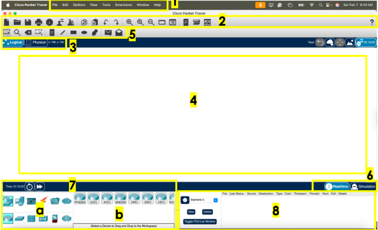
Workspace
This is the area where topologies are created and simulations are displayed. Area 4.
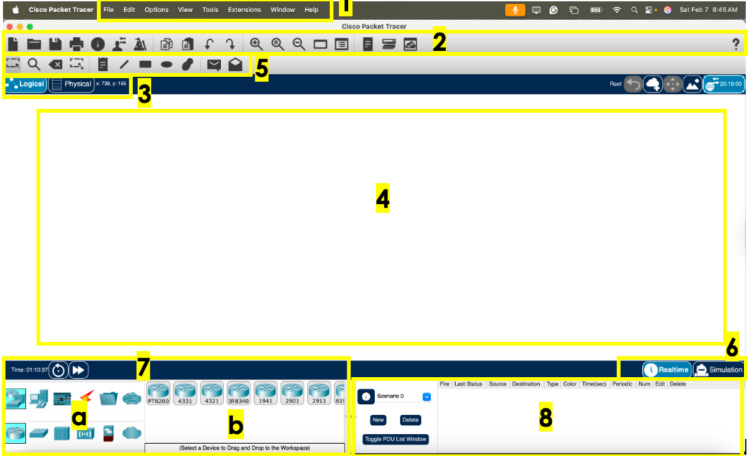
Common tools bar
This toolbar provides controls for manipulating topologies, such as select, move layout, place note, delete, inspect, resize shape, and add simple/complex PDU. Area 5.
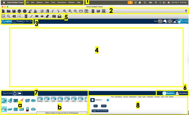
Realtime/Simulation tabs
These tabs are used to toggle between the real and simulation modes. Buttons are also provided to control the time and to capture the packets. Area 6.
Network Component Box
This component contains all of the network and end devices available with Packet Tracer, and is further divided into two areas. Area 7.
Area 7a: Device-type selection box
Area 7b: Device-specific selection box
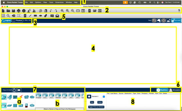
Device-type selection box
This area contains the device categories. Area 7a.
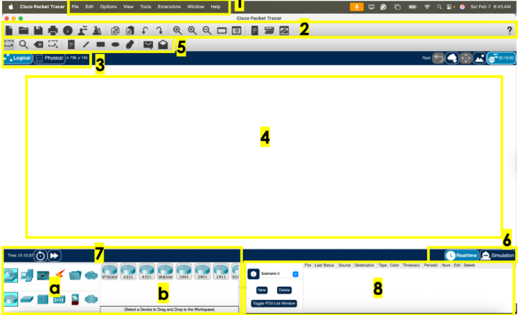
Device-specific selection box
When a device category is selected, this selection box displays the different device models within that category. Area 7b.
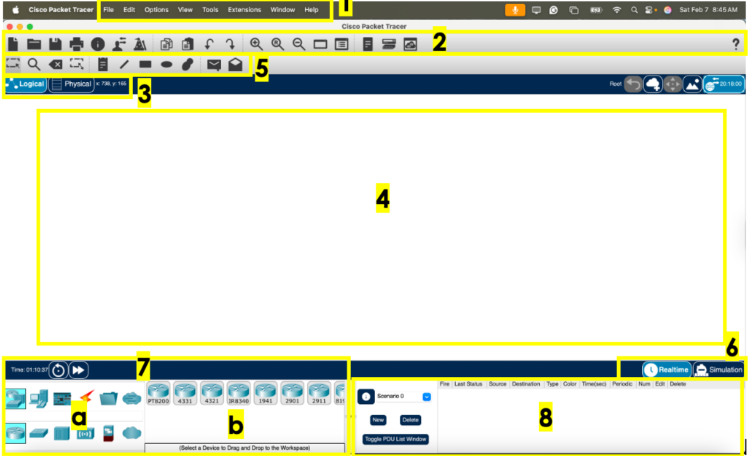
User-created packet box
Users can create highly-customized packets to test their topology from this area, and the results are displayed as a list. Area 8.