Development Length, Hooks and Splices & Design of Short Column
 Call Kai
 Learn
Learn Practice Test
 Spaced Repetition
 Match
Match Flashcards
 Knowt Play
1/54

Earn XP
Description and Tags
Reinforced Concrete Lesson 1
Name | Mastery | Learn | Test | Matching | Spaced | Call with Kai | Chat |
|---|
No analytics yet
Send a link to your students to track their progress
55 Terms
Bond between the steel and concrete after the concrete hardens
Joint behavior of Steen and concrete in a reinforced Concrete member
It requires a considerable forced to pull out the concrete
Straight bar of round section is embedded then
The steel bar may yield leaving some length of the bar in the concrete
Embedded length of the bar is long enough, then
Friction
Bonding force of concrete and steel is depend on its
Roughness of the surface area of the steel
Concrete mix
Shrinkage
Cover of the Concrete
Factors influencing the friction between the steel and concrete
Roughness of the surface area of steel
Deformed bar is referred due to its ridges formed than the plain bar
Concrete mix
Rich mixes have a great adhesion
Shrinkage
Frictional resistance
Cover of the concrete
Increase on it can improve the ultimate bon stress of a steel bar
Bond failure
Mechanism by which failure occurs when the provided development length is inadequate
Bond stress
Occurs the moment bending change
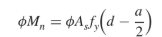
Max Moment in RC Formula

Theoretical Cutoff Locations for a simple span beam

Diagram for theorical cutoff location for a simple span beam

Development Length general formula for tension reinforcement

Transverse reinforcement index
Transverse reinforcement index
It is used to account for the contribution of confining reinforcing (stirrups/ties) across possible splitting planes
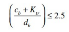
Provision of cover and transverse reinforcement terms
1.3
Value of Location Coefficient when 300 mm or above is placed1.0
1.5
Value of coating factor when it is coated with epoxy-coated or zinc with cover less 3db and spacing less than 6db
1.2
Value of coating factor when it is coated with epoxy-coated or zinc with cover more than 3db and spacing more than 6db
1.0
Value of coating factor when it is uncoated
1.0
Value of size of bar with 22-diameter or up
0.8
Value of size of bar factor when 19-diameter and below
1.0
Value of concrete weight factor when it is stated normalweight
0.85
Value of concrete weight factor when it is stated sand light0.weight
0.75
Value of concrete weight factor when it is stated lightweight
1.7
reinforcement location factor and epoxy coat factor shall not be greater than
300
Minimum length of development length in tension reinforcement
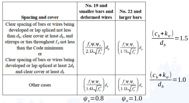
Simplified Version of Development length in Tension reinforcement
Do not have the cracks that develop in tension concrete members that cause a reduction in the bond between bars and the surrounding concrete
Why development length of deformed bars in compression is generally smaller?

Formula for Development Length in Compression Reinforcement
200 mm
Minimum length in compression reinforcement
a. Spiral
b. Circular continuously wound tie with db greater than or equal to 6 mm with a pitch of 100 mm
c. No 13 wire ties spaced less than or equal to 100 mm
d. Hoops spaced less than or equal to 100 mm
Confining factor provisions0
0.75
Value of confining reinforcement factor1.
1.0
value of confining reinforcement without confining reinforcement
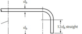
additional length in 90-degree hook

additional length in 180-degree hooked bar

hooks formula
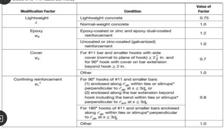
Modification factors for development of hooked bars in tension

Splices at tension reinforcement

Splices in compression reinforcement
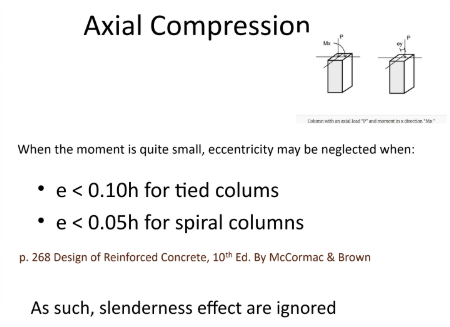
Axial Compression
0.65
Safety factor of Tied Columns0.
0.75
Safety factor of Spiral column
1%-8%
steel reinforcement ratio (min-max)
200-250 mm
minimum diameter of column
10-12 mm diameter
Size of Ties and Spiral

Center-to-center spacing of ties

formula for tied column

Formula for spiral column

gross reinforcement formula
25 mm
minimum pitch at spiral column
75 mm
maximum pitch at spiral column

Steel reinforcement ratio