Structural Analysis Revision Notes
1/24
There's no tags or description
Looks like no tags are added yet.
Name | Mastery | Learn | Test | Matching | Spaced |
|---|
No study sessions yet.
25 Terms
Permanent Actions Notation
Variable Actions Notation
Eurocode Notation - gk (kN/m²) or Gk (kN)
Eurocode Notation - qk (kN/m²) or Qk (kN)
Varying Distributed Load (VDL)
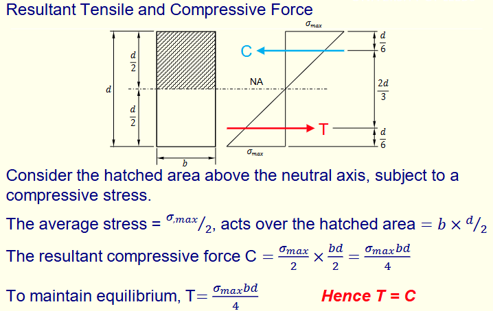
The line of action of W is at a distance (L/3) from the maximum intensity or at (2L/3) from the zero intensity.

Varying Partially Distributed Load (VPDL)
Two different weight one for the rectangular section and one for the triangular section.

Externally Statically Determinate Plane Structures
Degree of Redundancy = R - E
Where;
R : No. of Reactions (unknown)
E : Equation of Equilibrium = 3
Factors of Safety
Factor of Safety against Overturning = Restoring Moment / Overturning Moment
Factor of Safety Against Sliding = Total Reactive Forces Resisting Sliding / Total Forces Tending to Cause Sliding
Principle of Superposition
If a structure is made of linear elastic material and is loaded by combination of loads which do not strain the structure beyond the linear elastic range , then the resultant effect of the total load system on the structure is equivalent to the algebraic sum of the effect of each load acting separately.
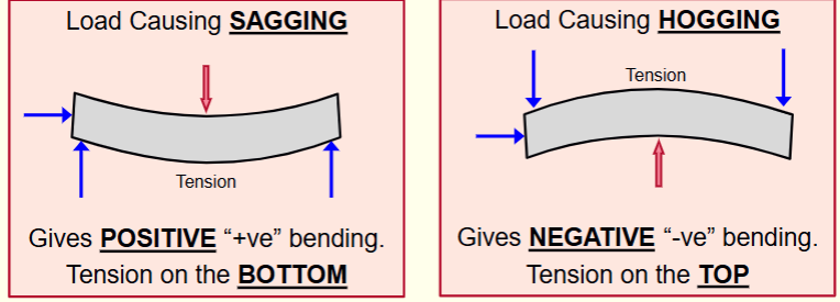
Bending Moments
Sagging => Gives positive “+ve” bending. Tension on the bottom.
Hogging => Gives negative "-ve" bending. Tension on the top.
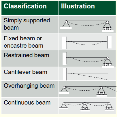
Deflected Shapes of Beams
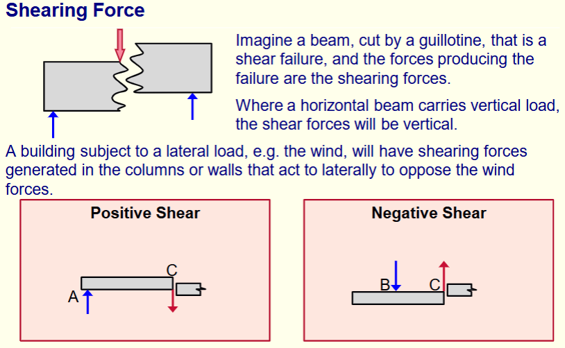
Shearing Force
Shear force is the internal resistance created in an elements cross sections, in
order to balance transverse external load acting on the element.
The shearing force at any section of an element or structure is the algebraic
sum of the lateral components of the forces acting on either side of the section.
Assumptions For Trusses
Truss members are connected together at their ends only, known as nodes
Truss members are connected together by frictionless pins at nodes, therefore cannot resist moments. Therefore, the sum of moments = 0 is automatically satisfied at a node.
The pin-jointed truss structure is loaded only at the nodes
The weight of the member may be neglected
It is assumed that all bars are two forces members. The weights of members are neglected compared to the forces they are supporting. Therefore, members work either in tension or compression
Shearing Force And Bending Moments
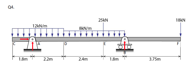
Maximum bending moment in the beam occurs at the position where there is zero shear. Zero shear occurs at a distance Lx1 (m) from the support at A. This can also be calculated using similar triangles.
X = (Shear force at D) / (UDL (KN/m) between D and E)
Lx1 = 2.2 + x = 2.2 + (6/8) = 2.95m
Max Bending Moment;
= +(54 × 2.95) - (12 × 4 × 2.74) - (8 × 0.74 × 0.37) = 25.6 KNm
Bending Moment At A;
= -(12 × 1.8 × 0.9) = -19.4 KNm
Bending Moment At B;
= -(18 × 3.75) = -67.5 KNm
Bending Moment At E; two point on E one at end of the UDL and one at the midspan
= -(12 × 4 × 2) + (54 × 2.2) = 22.8 KNm
Bending Moment At E;
= -(12 × 4 × 4.4) + (54 × 4.6) - (8 × 2.4 × 1.2) = 14.2 KNm
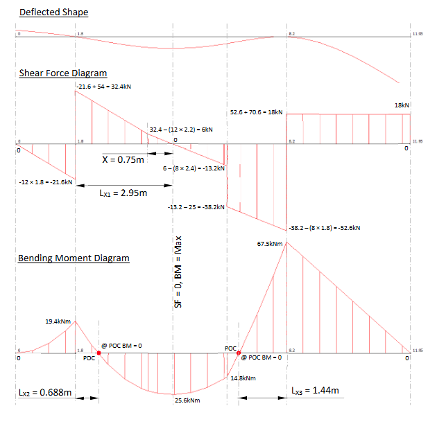
Distance Of Lx2;
-12 x (1.8 + Lx2)((1.8 + Lx2) / 2) + (54 x Lx2) = 0
(-21.6 - 12Lx2)(0.9 + 0.5Lx2) + 54Lx2 = 0
-19.44 - 1.8Lx2 - 10.8Lx2 - 6Lx2² + 54Lx2
-6Lx2² + 32.4Lx2 -19.44 = 0
Lx2 = 0.688m
Distance Of Lx3;
-18 x (3.75 + Lx3)((8 x Lx3 x Lx3)/2) + (70.6 x Lx3) = 0
-67.5 - 18Lx3 - 4Lx3² + 70.6Lx3
-4Lx3² + 52.6Lx3 - 67.5 = 0
Lx3 = 1.44m
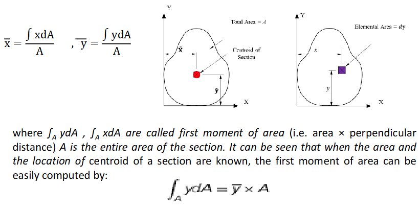
Centroid Of A Section
The centre of mass or the centre of gravity. The location of the centroid is defined by x and y coordinates from a set of reference axes.
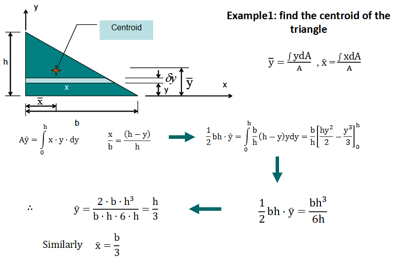
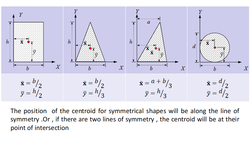
Centroid Of A Right Angle Triangle
Xbar = Base / 3
Ybar = Height / 3
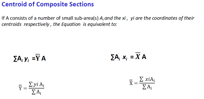
General Centroid Formulas
Sum of Ai*yi = Ybar*A
Sum of Ai*Xi = Xbar*A
Ybar = (Sum of Yi*Ai) / (Sum of Ai)
Xbar = (Sum of XI*Ai) / (Sum of Ai)
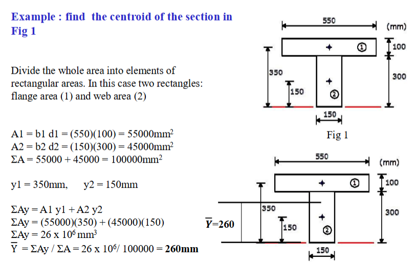
Find The Section Of The Section
Example
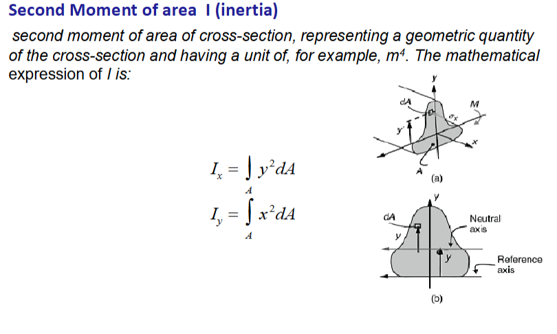
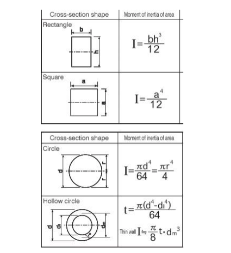
Second Moment Of Area I (Inertia)
Second moment of area of cross-section, representing a geometric quantity
of the cross-section and having a unit of, for example, m4. The mathematical
expression of I is:
Second Moment Of Area For Different Sections
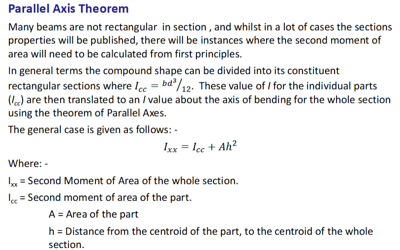
Parallel Axis Theorem
A theorem used to calculate the moment of inertia of a beam or object about any axis, given its moment of inertia about a parallel axis through its centroid.
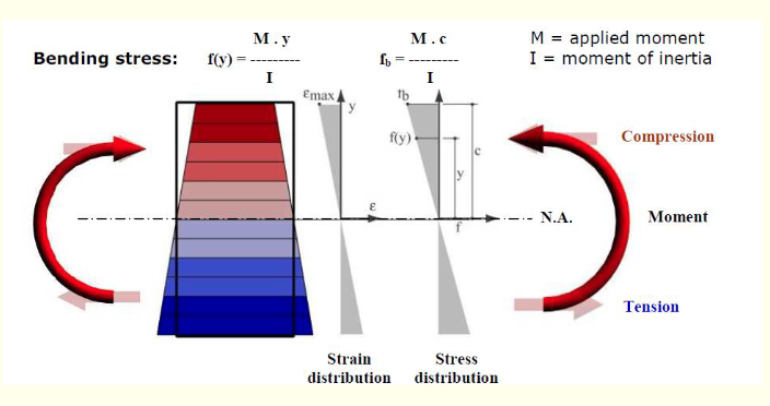
Bending Stress Definition
Are longitudinal stresses, acting parallel to the longitudinal axis of the beam, which may be either tensile or compressive. These stresses are induced by the application of a bending moment on beam cross sections.
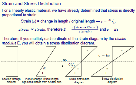
Stress And Strain Distribution
For linear elastic materials, stress is directly proportional to strain
Resultant Tensile And Compressive Force
Moment Of Resistance Of A Rectangular Section
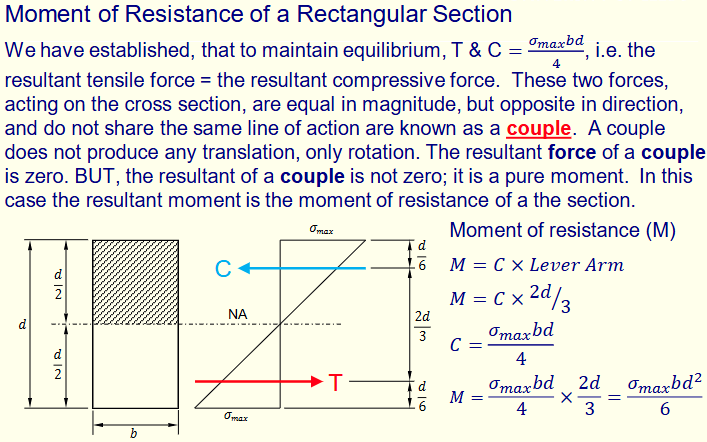
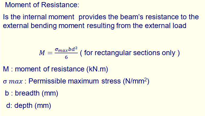
Moment Of Resistance For Rectangular Section
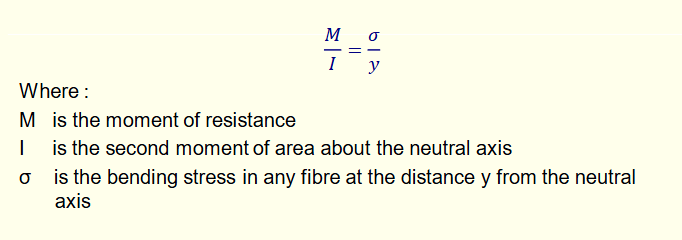
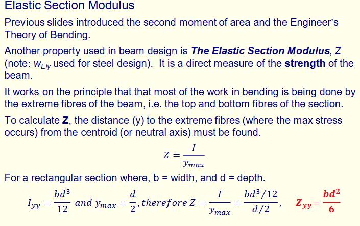
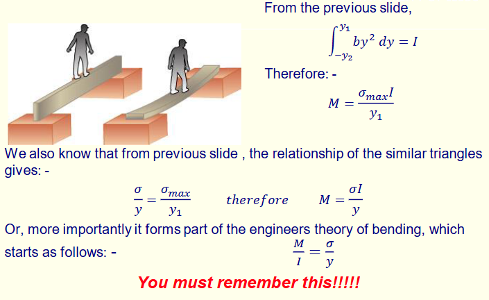
Engineers Theory Of Bending
Elastic Section Modulus