Conventional Machining (L4,5,6)
1/93
There's no tags or description
Looks like no tags are added yet.
Name | Mastery | Learn | Test | Matching | Spaced | Call with Kai |
|---|
No analytics yet
Send a link to your students to track their progress
94 Terms
CONVENTIONAL MACHINING processes
Material is removed with a specifically shaped cutting tool in the form of small “chips”.
When machining, we want to…
Remove material as quickly as possible
Maintain acceptable geometric accuracy & surface finish
Not break or excessively deflect/wear tool
Cutting Forces/Taylor Tool Life calculations
Minimize non-cutting time (set-ups, stock load/part unload, tool changes)
jig
It has all the characteristics of a fixture, but also provides a means of guiding the tool during the operation
Fixture
work-holding device (usually custom designed) for a particular part
Advantages of machining
Can machine most solid materials
Can machine complex geometry parts
Tight tolerances (± 0.001”)
Good surface finish
Disadvantages of machining
Time consuming
Wasteful (chips)
Large energy use
Rotational Work Part
cylindrical or disk-like shape
This geometry involves a cutting tool removing material from a rotating work part.
Non-Rotational Work Parts (prismatic work part)
block-like and plate-like shape
Geometry is achieved by linear motions of the work part
generating
part geometry is determined by the feed trajectory of cutting tool
Types of generating processes
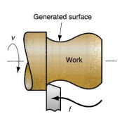
(a) Straight turning
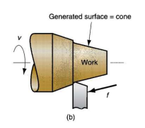
(b) Taper turning
(c) Contour turning
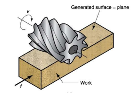
(d) Plain milling
(e) Profile milling
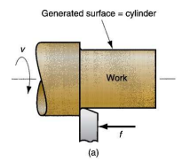
What generating process is shown?
straight turning
What generating process is shown?
taper turning
What generating process is shown?
contour turning
What generating process is shown?
plain milling
What generating process is shown?
Profile milling
Forming
part geometry is created by the shape of the cutting tool
Types of forming processes
(a) Form turning
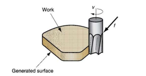
(b) Drilling
(c) Broaching
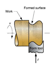
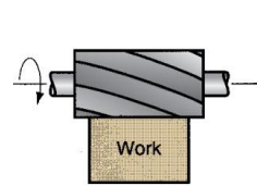
What forming process is shown?
Form turning
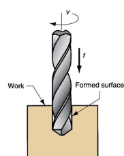
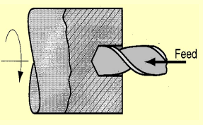
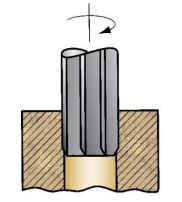
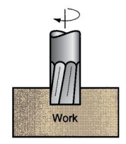
What forming process is shown?
Drilling
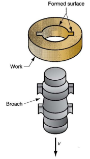
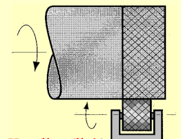
What forming process is shown?
Broaching
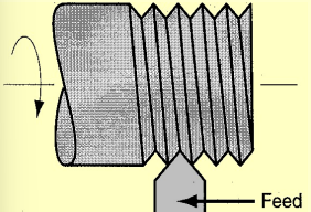
What are the processes that are a combination of forming and generating
thread cutting, slot milling
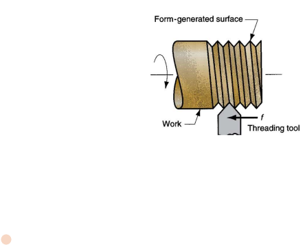
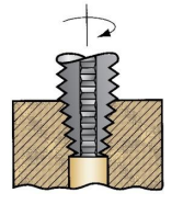
What process is shown?
Thread cutting
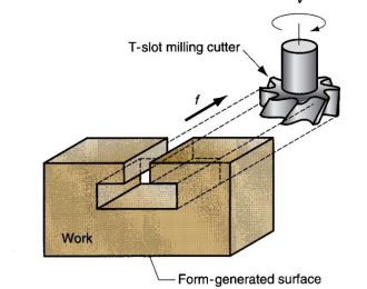
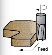
What process is shown?
slot milling
Three general common machining operations
turning, drilling, milling
Types of turning operations
facing, shaping, cut-off, threading, drilling, knurling, boring
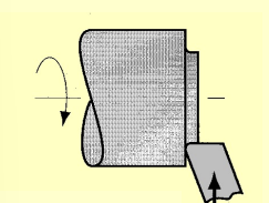
What turning process is shown?
facing
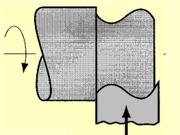
What turning process is shown?
shaping
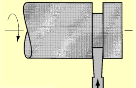
What turning process is shown?
cut-off
What turning process is shown?
threading
What turning process is shown?
drilling
What turning process is shown?
knurling
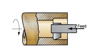
What turning process is shown?
boring
Drilling
Round rotating tool fed axially into workpiece
Turning is commonly accomplished on what type of machine?
lathe
Drilling is commonly accomplished on what type of machine?
drill press
Through hole
drill exits opposite side of work
Blind hole
drill does not exit opposite side of work
What drilling operation is shown?
Reaming
What drilling operation is shown?
Tapping
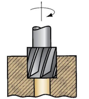
What drilling operation is shown?
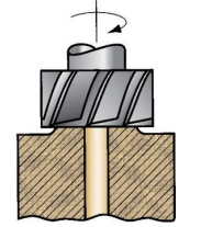
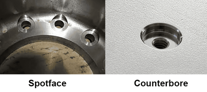
Counterboring
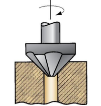
What drilling operation is shown?
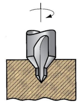
Countersinking
What drilling operation is shown?
Center Drilling
What drilling operation is shown?
Spot facing
Reaming
Unlike drill bits, reamers are available in ANY size diameter. Used to remove very little material. Finishing operation.
Countersinking
Add chamfers to holes or creates geometry needed to house a flat head fastener
Center Drilling
used to create accurately located pilot holes for subsequent drilling or for a lathe’s tailstock center to support workpiece
Spot Facing
Used for producing a flat seat for a bolt head, washer, or nut
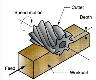
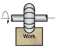
Peripheral Milling
Cutter axis parallel to surface being machined. Cutting edges on outside periphery of cutter. Use a horizontal milling machine
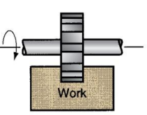
What type of peripheral milling is this?
slab milling
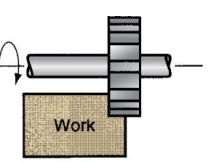
What type of peripheral milling is this?
slotting
What type of peripheral milling is this?
side milling
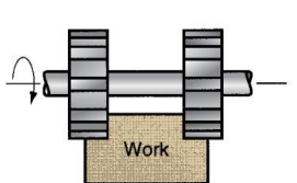
What type of peripheral milling is this?
Straddle milling
What type of peripheral milling is this?
Form Milling
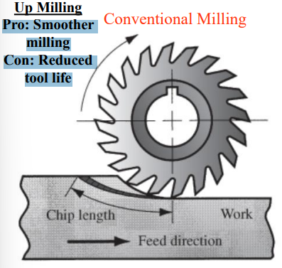
Up Milling (Conventional Milling)
Cutter teeth rotate opposite to feed direction
Pro: Smoother milling
Con: Reduced tool life
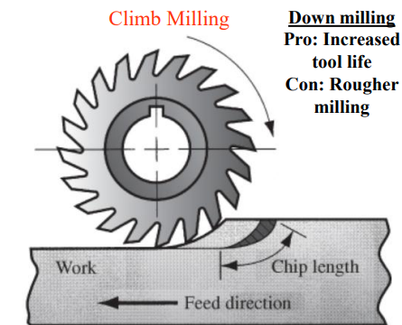
Down Milling (Climb Milling)
Cutter teeth rotate same as feed direction
Pro: Increased tool life
Con: Rougher milling
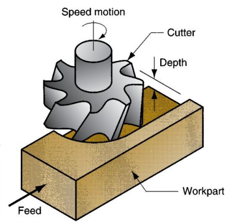
Face Milling
Cutter axis perpendicular to surface being milled. Cutting edges on both the end and outside periphery of the cutter. Uses Vertical milling machining`

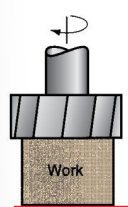
What type of face milling is shown?
Conventional Face milling

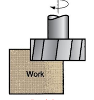
What type of face milling is shown?
Partial Face Milling
What type of face milling is shown?
End Millling
What type of face milling is shown?
Profile Milling

What type of face milling is shown?
Pocket Milling

What type of face milling is shown?
Surface Contouring
Conventional Face Milling
Diameter of cutter is greater than the work part width
Partial Face Milling
Diameter of the cutter overhangs the work only on one side
End Milling
Diameter of cutter is less than the work width, so a slot is cut into the part

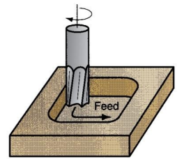
Profile Milling
A form of end milling in which the outside periphery of a flat part is cut

Pocket Milling
Another form of end milling to cut shallow pockets into parts
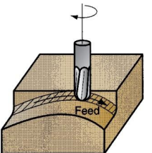
Surface Contouring
Creates 3D surface form. Typically using a ball-nose cutter rather than a square-end cutter
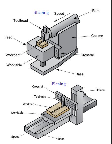
Shaping & Planing
A straight, flat surface is created in both operations. Similar operations, both use a single point cutting tool moved linearly relative to the work part
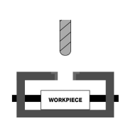
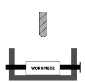
Planing: Part moves
Shaping: Tool Moves
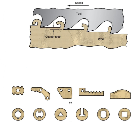
Broaching
A multiple tooth cutting tool is moved linearly relative to work in direction of tool axis. Variety of work shapes possible
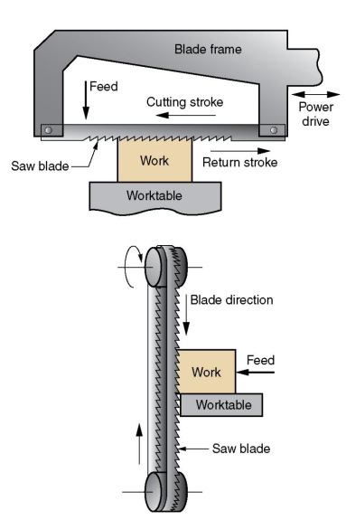
Sawing
Cuts narrow slit in work by a tool consisting of a series of narrowly spaced teeth
What are the types of special geometries
external screw threads, internal screw threads, gears
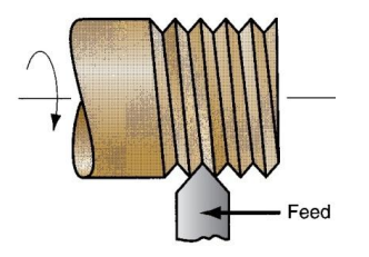
Methods of producing external screw threads
Single-point thread cutting
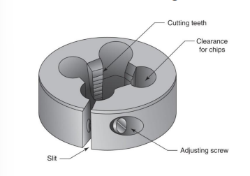
Threading die
Thread chasing using self-opening threading dies
Thread milling
Thread rolling
Single-point thread cutting
Simplest and most versatile method of cutting threads. Single point cutting tool on the lathe
Thread die
Cut threads in a single pass rather than multiple passes, as in single-point threading
Thread chasing using self-opening threading dies
Similar to threading dies, but is equipped with an automatic device that opens the cutting teeth at the end of the cut
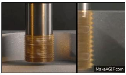
Thread milling
Use form-milling cutter to shape the threads of a screw. Can create internal and external threads
Thread rolling (“forming”)
Most common method for producing external threads. Process is not economical for low production quantities
Methods for producing internal screw threads
Tapping
Collapsible taps
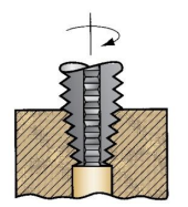
Tapping
Cylindrical tool with cutting teeth arranged in spiral, whose pitch is equal to that of the desired screw threads
Collapsible taps
Similar to self-opening threading dies
Cutting teeth retract for quick removal from hole
Methods for producing gears
Form milling
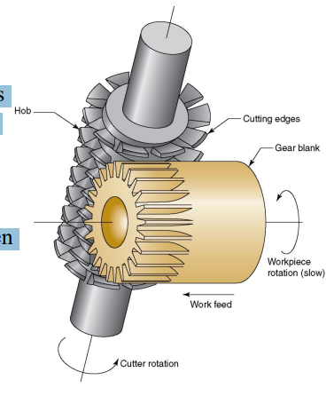
Gear hobbing
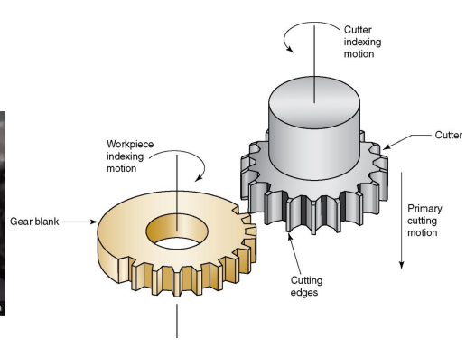
Gear shaping
Gear broaching - for internal and external gears
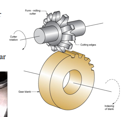
Form milling
Cutter has teeth with the shape of the spaces between teeth on the gear. Gear blank is indexed between each pass to establish correct size of the gear tooth
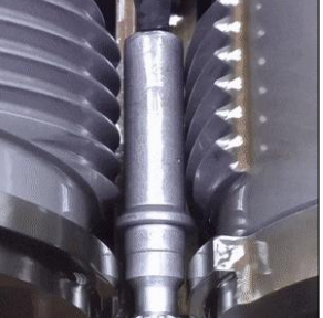
Gear hobbing
Hob has a slight helix and its rotation is coordinated with much slower rotation of the gear blank.
Special milling machines (called hobbing machines) accomplish the relative speed and feed motions between cutter and gear blank
Gear shaping
To start the process, cutter is gradually fed into gear blank. Then, cutter and blank are slowly rotated after each stroke to maintain tooth spacing
Gear Broaching
For internal gears, broach consists of a series of gear-shaped cutting teeth of increasing size to form the gear teeth in successive steps as broach is drawn through starting hole.
For external gears, broach is tubular with inward-facing cutting teeth
What are the 3 possible modes by which a cutting tool can fail in machining
Fracture failure
Temperature failure
Gradual wear
Fracture Failure
Cutting forces at the tool point becomes excessive, causing it to fail suddenly by brittle fracture
Temperature failure
Cutting temperature is too high for the tool material, causing the material at the tool point to soften. Leads to plastic deformation and loss of the sharp edge
Gradual Wear
Gradual wearing of the cutting edge causes loss of tool shape, reduction in cutting efficiency, and acceleration of wearing as the tool becomes heavily worn.
What are the two location gradual wear occurs?
Crater wear
Flank wear
Crater Wear
occurs on top rake face
Flank Wear
Occurs on flank (side of tool)
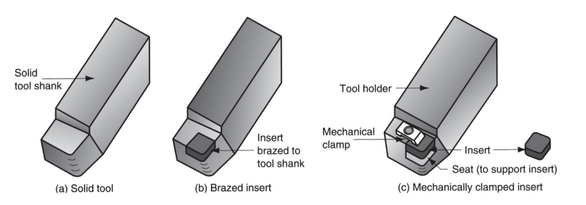
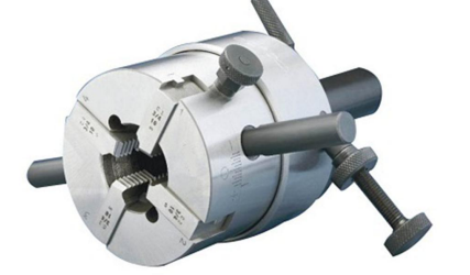
What are the 3 different cutting tools for turning?
Solid tool, brazed insert, mechanically clamped insert