Chapter 19 Paralleling Technique, Radiology 1
1/64
There's no tags or description
Looks like no tags are added yet.
Name | Mastery | Learn | Test | Matching | Spaced |
|---|
No study sessions yet.
65 Terms
Paralleling technique is also known as -what is it used to expose?
-Extension Cone Paralleling Technique (XCP)
-right-angle technique
- long-cone technique
Used to expose periapical and bitewing image receptors
Parallel
Moving or lying in the same plane, always separated by the same distance. Not intersecting.
Intersecting
to cut across or through
Perpindicular
Intersecting at or forming right angles
Right angle
an angle of 90 degrees formed by two lines perpendicular to each other
Long axis of the tooth
Imaginary line dividing the tooth longitudinally (vertically) into two equal halves
Central ray
The central portion of the primary beam of x-radiation
The paralleling technique is based on the concept of
parallelism
The basic principles of paralleling technique are
1. The receptor is placed in the mouth parallel to the long axis of the tooth being radiographed
2. The central ray of the X-ray beam is directed perpendicular (at a right angle) to the receptor and the long axis of the tooth.
3. A beam alignment device must be used to keep the receptor parallel with the long axis of the tooth. The patient cannot hold the receptor in this manner
Rules for paralleling technique
Receptor covers area to be examined
•Thereceptorr is placed parallel to the long axis of the tooth being examined
• The central ray of the X-ray beam is directed perpendicular to the receptor and the long axis of the tooth
• Vertical angulation: central ray perpendicular to receptor/long axis of the tooth
• Horizontal angulation: central ray through contacts between teeth
• Failure to center beam to receptor results in closed contacts
To achieve parallelism between the receptor and the tooth, the ___ distance must be increased to keep the receptor parallel with the long axis of the tooth.
object receptor distance (distance between tooth and receptor)
To achieve parallelism between the receptor and the tooth the receptor must be placed
away from the tooth and toward the middle of the oral cavity
increased object-receptor distance
results in increased image magnification
Target-receptor distance
distance between source of x-rays and receptor
To compensate for image magnification the target receptor distance must also be
increased to ensure that only the most parallel rays will be directed at the tooth and receptor
long (16 inch) target receptor distance must be used with
paralleling technique
Sometimes called long cone technique
long refers to the length of the cone or the PID
What results in less image magnification and increased definition
Long target receptor distance
A rectangular collimator is used in this technique to
reduce the amount of radiation that the patient recieves
Paralleling technique requires the use of a
beam alignment device or a receptor holder to position the receptor parallel to the long axis of the tooth
Beam alignment devices
used to position an intraoral receptor in the mouth and maintain the receptor in position during exposure
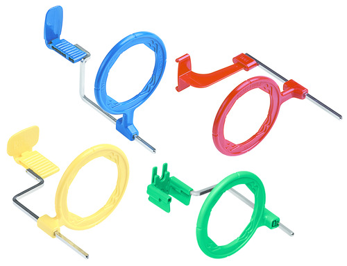
Examples of commercially available intraoral beam alignment devices include the following Dentsply Rinn products
-The Rinn XCP extension cone paralleling technique
-The Rinn XCP-ORA
-The Rinn XCP-DS FIT universal sensor holder
-The Rinn flip-ray system
The Rinn XCP extension cone paralleling
-Includes 3 plastic bite blocks, 3 plastic aiming rings, and 3 metal indicator arms.
-Different bite blocks are available that accommodate film and PSP sensors, as well as digital sensors.
-The plastic bite blocks are color-coded to aid in assembly
-blue used in the anterior regions
-yellow used in the posterior regions
-red are used for bite wing projections
- green are used in endodontic procedures
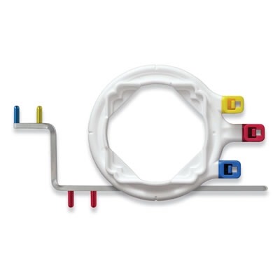
The Rinn XCP-ORA
Reduced number of component parts- (One Ring & Arm) one aiming ring and one indicator arm; different bite blocks for different receptor sizes
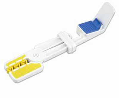
The Rinn XCP-DS FIT universal sensor holder
Bite block that includes self-adjusting clip that stretches to accommodate the size of the digital sensor regardless of what brand or size.
-These bite blocks may be used with the Rinn XCP or Rinn XCP-ORA systems

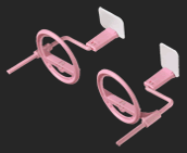
The Rinn flip-ray system
uses a rotating bite-block and ring to eliminate multiple positioning parts
-May be used with film or PSP sensors
Examples of receptor holding devices that are used with the paralleling technique to position an intra oral receptor are
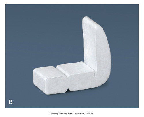
The stabe bite block
Rinn Snap A Ray holder
The Rinn snap a ray holder
Comes in two versions, one for film and one for digital sensors. This receptor holding device can be used in both anterior and posterior areas
The stabe bite block
a disposable receptor holder made of Styrofoam and is designed for one time use only
The Rinn XCP beam alignment device insturments are recommended for exposure of
periapical receptors- they aid in the alignment of PID with receptor
The size of the intraoral receptor used with the paralleling technique depends on
which teeth are being radiographed
Anterior teeth
-Size 1 receptor is used
-This narrow size is needed to permit placement high in the palate without bending or curving.
Size 1 is always positioned with the long portion of the receptor in a
vertical (upright) direction
Posterior region
Size 2 receptor is used.
Size 2 is always placed with the long portion of the receptor in a horizontal (sideways) direction
5 basic rules should be followed when using the paralleling technique
1. Receptor placement- it must be positioned to cover the prescribed area of the tooth to be examined.
2. Receptor position- it must be positioned parallel to the long axis of the tooth. The receptor and beam alignment device must be placed away from the teeth and toward the middle of the oral cavity
3. Vertical angulation- The central ray of the x-ray beam must be directed perpindicular (at a right angle) to the receptor and long axis of the tooth.
4. Horizontal angulation- the central ray of the x-ray beam must be directed through the contact areas between the teeth.
5. Receptor exposure- The x ray beam must be centered on the receptor to ensure that all areas are exposed. Failure to center the x-ray beam results in a partial image on the receptor or a "cone-cut". Cone cuts can either be produced with a round or rectangular PID.
Size ____would be used on pedo (child) patient for post/ant images, but in some cases, size 1 or 2 may be used depending on age of the child
0
Patient Prep
• Explain the procedure: "inform before you perform"
• Adjust chair and headrest (maxillary parallel to the floor, midsaggital plane perpendicular to the floor)
• Place lead apron/thyroid collar on pt.
• Remove all objects such as eyeglasses. Any other items to remove prior to exposure? Dentures, retainers
Equipment prep
After patient prep all equipment must be prepared before the exposure of any receptors
Set all exposure factors such as (_) BEFORE placing receptor in mouth
kv, ma
Open sterilization bags and glove when assembling receptor holder
place receptor in holder
Make sure receptor is
centered when looking through aiming ring!!!!!
Exposure sequence
A definite order for periapical receptor placement and exposure that must be followed in the placement and exposure of intraoral films.
Anterior exposure sequence
-Begin with the maxillary right canine tooth
-Expose all of the maxillary anterior teeth
-End with the maxillary left canine
-Move to the mandibular arch
-Begin with the mandibular left canine
-Expose all of the mandibular anterior teeth
-Finish with the mandibular right canine
Why do you always begin with the anterior teeth? when exposing periapical receptors
The size 1 receptor used for anterior exposures is small, less uncomfortable, and easier for the patient to tolerate. Some practitioners use a size 2 receptor instead, which may be more difficult to place.
-The more tolerable anterior placements allow the patient to become more accustomed to the beam alignment device used in the paralleling technique.
-anterior is less likely to cause the patient to gag.
With size 1 receptor, a total of _ anterior receptor placements are used in the paralleling technique.
7 anterior, 4 maxillary exposures and 3 mandibular exposures
If size 2 is used then there are _ anterior receptor placements
6- 3 maxillary and 3 mandibular
Exposure sequence for the Rinn XCP beam alignment device is
1. assemble the anterior Rinn XCP instrument
2. Begin with the maxillary right canine (tooth 6)
3. Expose the anterior teeth working from the patients right to the patients left.
4. End with the maxillary left canine (tooth 11)
5. Next move to the mandibular arch
6. Begin witht the mandibular left canine (tooth 22)
7. Expose all the mandibular anterior teeth working from the patients left to right.
8. Finish with the mandibular right canine (tooth 27)
Posterior exposure sequence for paralleling technique
Always expose the premolar receptor first and then the molar receptor
-Premolar easier for the patient
-less likely to gag
____ posterior placements may be used
8- 4 maxillary exposures and 4 mandibular exposures
Posterior periapical exposure sequence for the XCP
1. begin with the maxillary right quadrant
2. assemble the posterior Rinn XCP Instrument
3. First expose the premolar receptor(teeth 4 and 5) then expose the molar receptor (teeth 1, 2 and ,3)
4. Don't reassemble, move to the mandibular left quadrant
5. Expose the premolar receptor (teeth 20 and 21) then expose the molar receptor (teeth 17, 18, and 19)
6. reassemble the posterior rinn XCP over a covered work surface
7. next move the the maxillary left quadrant
8. Expose the premolar receptoir (teeth 12 and 13) and then expose the molar receptor (14, 15, and 16)
9. finish with the mandibular right quadrant
10. expose the premolar receptor (28 and 29) and then expose the molar receptor (30, 31, and 32)
Shallow palate or "low palatal vault"
use cotton rolls on bite-block---run it with the length of the receptor biteblock
-Adjust vertical angulation by 5-15 degrees sometimes distortion occurs
Bony growths: Tori/Torus
Maxillary "torus palatinus": place receptor on far side of tori/torus---never on tori •
Mandibular "torus mandibularis": place receptor between tori/torus and tongue---never on tori
receptor placement
The specific area where the receptor must be positioned before exposure.
The anterior Rinn XCP is used for all
anterior receptor placements
After the anterior rinn XCP has been assemled a size 1 receptor is inserted vertically into the bite block and secured in the slot.
a total of 7 anterior placements including the following
- two maxillary canine exposures
-Two maxillary incisor exposures
-two mandibular canine exposures
-one mandibular incisor exposure
posterior receptor placement
The posterior Rinn XCP- after the posterior Rinn XCP has been assembled a size 2 receptor is inserted horizontally into the bite block and secured.
-A total of 8 posterior placements include the following
- two maxillary premolar exposures
-two maxillary molar exposures
-two mandibular premolar exposures
-two mandibular molar exposures
torus
A bony growth in the oral cavity
maxillary torus
a nodular mass of bone seen along the midline of the hard palate
mandibular torus
Bone growth noted on the lingual aspect of the mandibular arch.
advantages of paralleling technique
-accuracy: the image is free of distortion.
-simplicity: eliminates the need to determine horizontal and vertical angulation. eliminates chances of dimensional distortion.
-duplication: comparison of serial radiographs has great validity.
disadvantages of paralleling technique
-Receptor placement may be difficult
-Discomfort: beam alignment device may cause discomfort
What happens to the image when the object-receptor distance is increased?
Increased image magnification & Loss of definition
For the paralleling technique the exposure of the mandibular incisors should show
Entire crowns & roots of 4 mandibular incisors.
Contacts of the central incisors must be visible.
For the paralleling technique the exposure of the mandibular canine should show
entire crown & root of canineInterproximal alveror bone
Mesial & distal contacts
For the paralleling technique the exposure of the maxillary canine should show
entire crown & root of canine
Apex
alveror bone
Mesial Contact
For the paralleling technique the exposure of the maxillary incisors should show
entire crown & root of one lateral & one central incisor
Mesial contact of the adjacent central incisor & Mesial contact of the adjacent canine