Chapter 7: The X-Ray Tube
 Call Kai
 Learn
Learn Practice Test
 Spaced Repetition
 Match
Match Flashcards
 Knowt Play
1/92

There's no tags or description
Looks like no tags are added yet.
Name | Mastery | Learn | Test | Matching | Spaced | Call with Kai | Chat |
|---|
No analytics yet
Send a link to your students to track their progress
93 Terms

Rotor
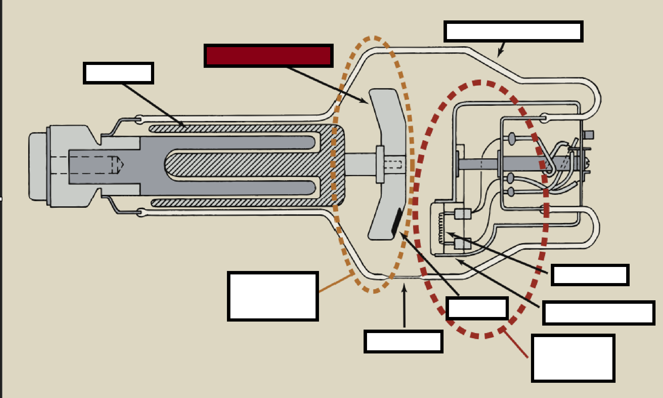
Rotating Anode

Glass enclosure

Anode assembly

window

Target

Filament

Focusing cup
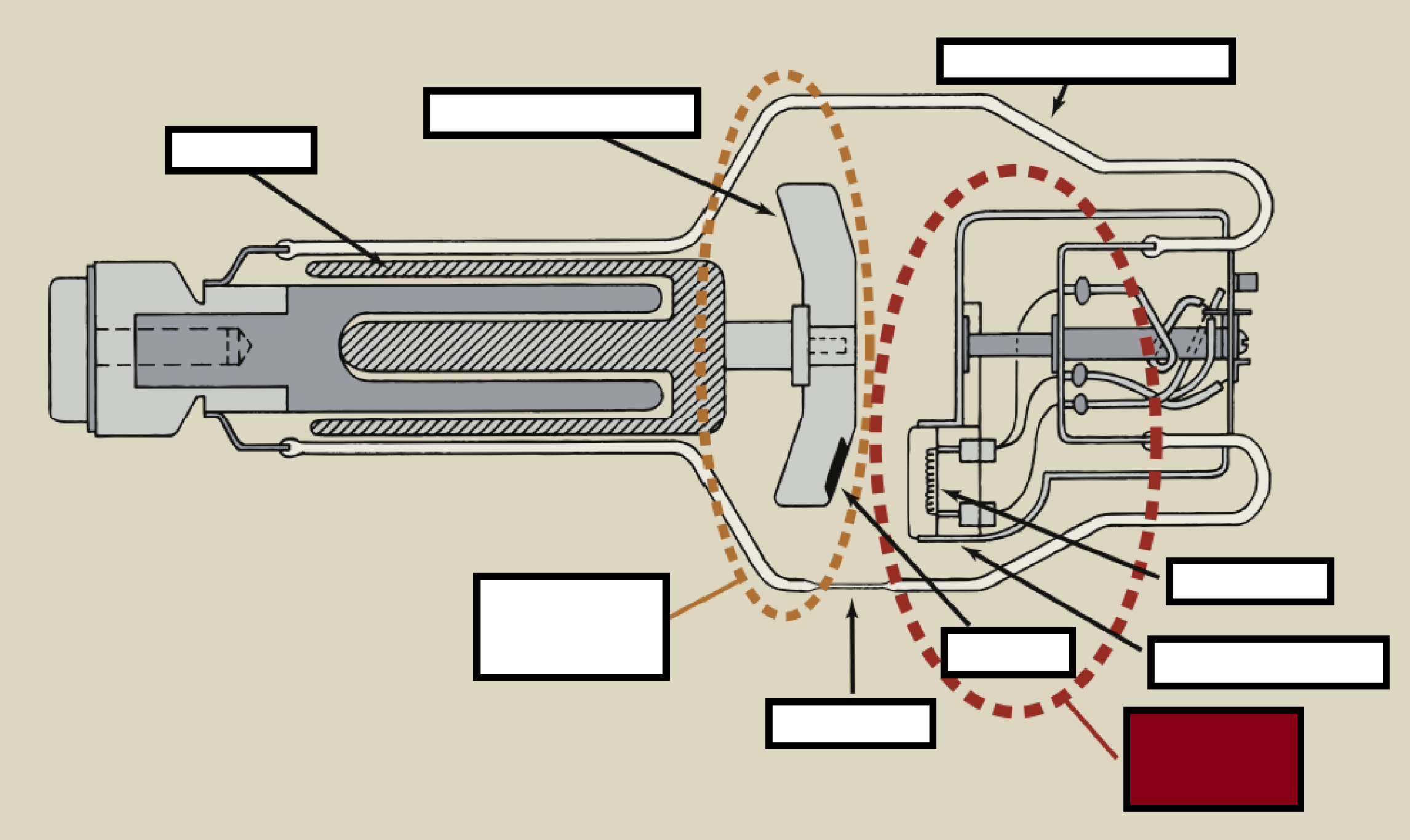
Cathode assembly

Rotating anode x-ray tube
External components of an X-ray tube
Support structure, protective housing, glass or metal enclosure
Internal components of an x-ray tube
anode and cathode
types of support structures
ceiling support system, floor-to-ceiling support system, C-arm support system
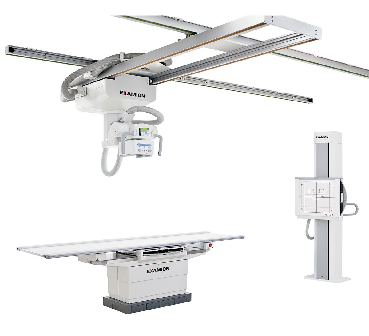
Ceiling support system
The most common support system; uses two perpendicular ceiling rails for longitudinal and transverse movement. A telescoping column connects the tube housing to the rails, allowing the SID to be adjusted.

Floor-to-Ceiling Support System
Uses a single column with rollers attached to ceiling and floor rails. The X-ray tube moves up and down the column, while the column can rotate to position the tube.

C-Arm Support System
A C-shaped, ceiling-mounted support that allows very flexible tube positioning. The image receptor is attached to the opposite end of the C-arm from the X-ray tube.
Protective Housing
The outer housing surrounding the X-ray tube that reduces leakage radiation, protects against electric shock, provides mechanical support, and protects the tube from damage.
Window
The special section of the X-ray tube housing through which X-rays are allowed to exit.
Useful Beam
The X-rays that exit through the window of the tube housing and are used to produce the diagnostic image.
Leakage Radiation
X-rays that escape through the protective housing instead of exiting through the window; they provide no diagnostic information and cause unnecessary exposure.
Isotropic Emission
The emission of X-rays with equal intensity in all directions when they are produced.
High-Voltage Receptacles
Special connections built into the protective housing that protect against accidental electric shock from the high voltage used by the X-ray tube.
Insulating Oil
Oil inside some protective housings that insulates against electric shock and helps dissipate heat from the X-ray tube.
Cooling Fan
A fan in some protective housings that cools the X-ray tube or the oil surrounding it.
Microswitch
A safety switch that activates if the oil expands too much from excessive heat, preventing the tube from being used until it cools.
Glass or Metal Enclosure
A sealed vacuum enclosure containing the X-ray tube's two electrodes: the cathode and anode. Modern high-capacity tubes commonly use metal enclosures.
Vacuum tube
The absence of gas inside the X-ray tube. It allows electrons to flow more efficiently from the cathode to the anode, producing more X-rays and extending tube life.
Gassy Tube
An X-ray tube in which gas has entered the enclosure. This reduces electron flow, decreases X-ray production, increases heat, and can eventually cause tube failure.
Coolidge Tube
The modern X-ray tube, which is a vacuum tube. Unlike early Crookes tubes, it contains essentially no gas.
Crookes Tube
An early X-ray tube that contained a controlled amount of gas rather than being a true vacuum tube.
Tungsten Vaporization
The process in which tungsten from the tube vaporizes and coats the inside of a glass enclosure as the tube ages.
Arcing
An electrical discharge that can occur when tungsten deposits alter the electrical properties of a glass tube, potentially causing tube failure.
Metal Enclosure
maintains a constant electrical potential between the tube's electrical current and the enclosure, making the tube less likely to fail and longer-lasting.

Lead

Leakage radiation
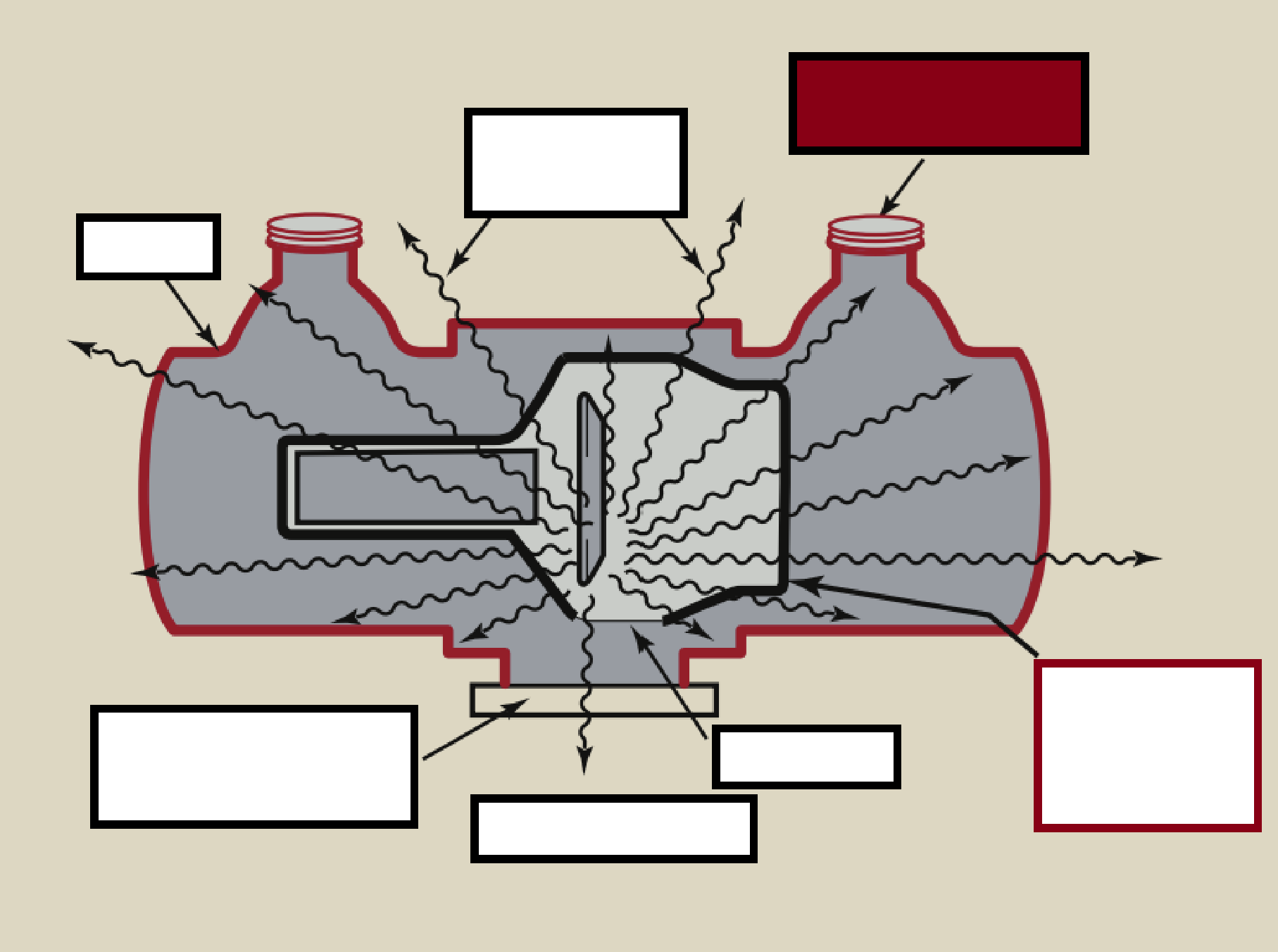
High-voltage connector
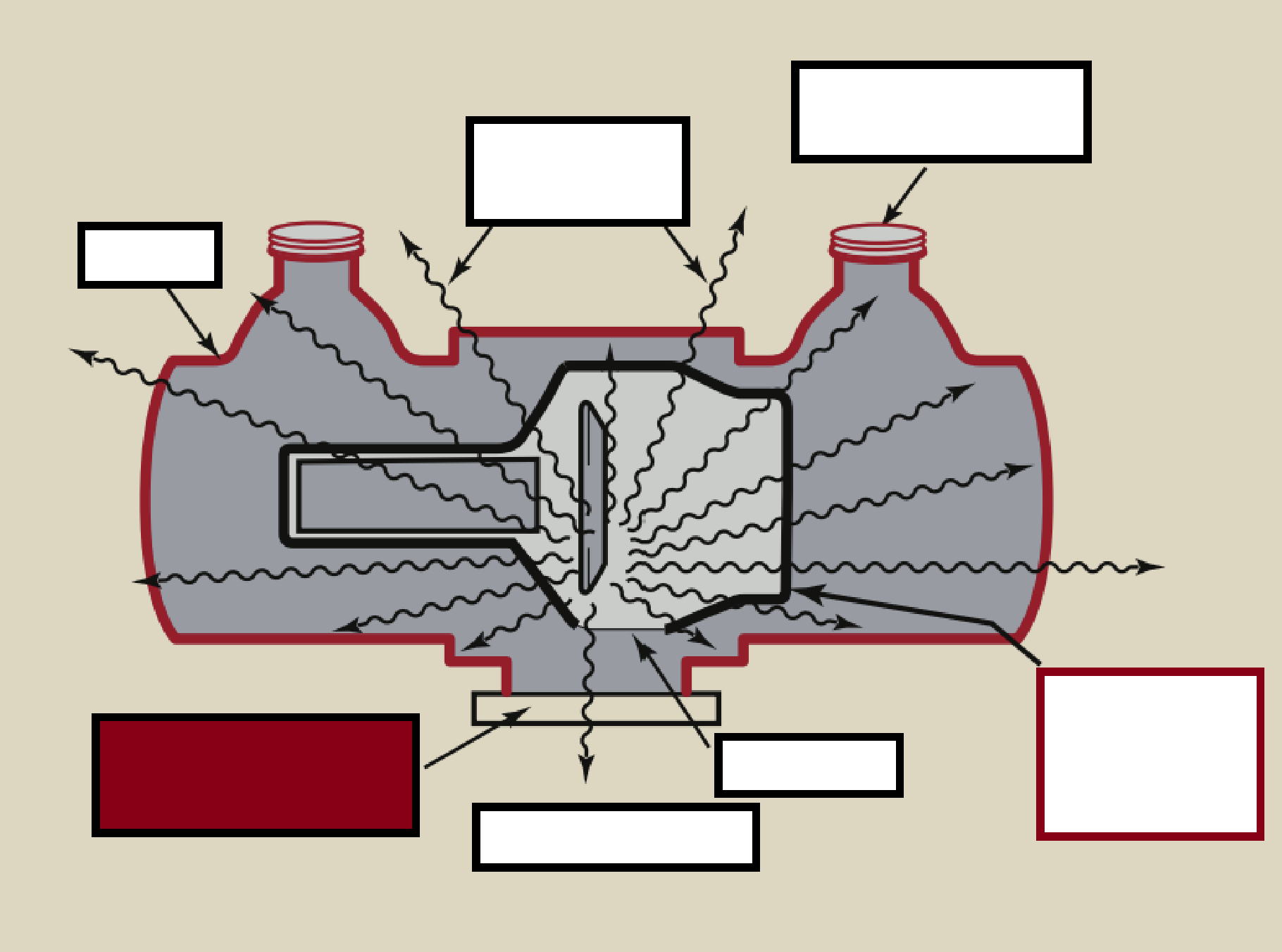
Fitting for filters, collimators, etc

Useful beam

Window
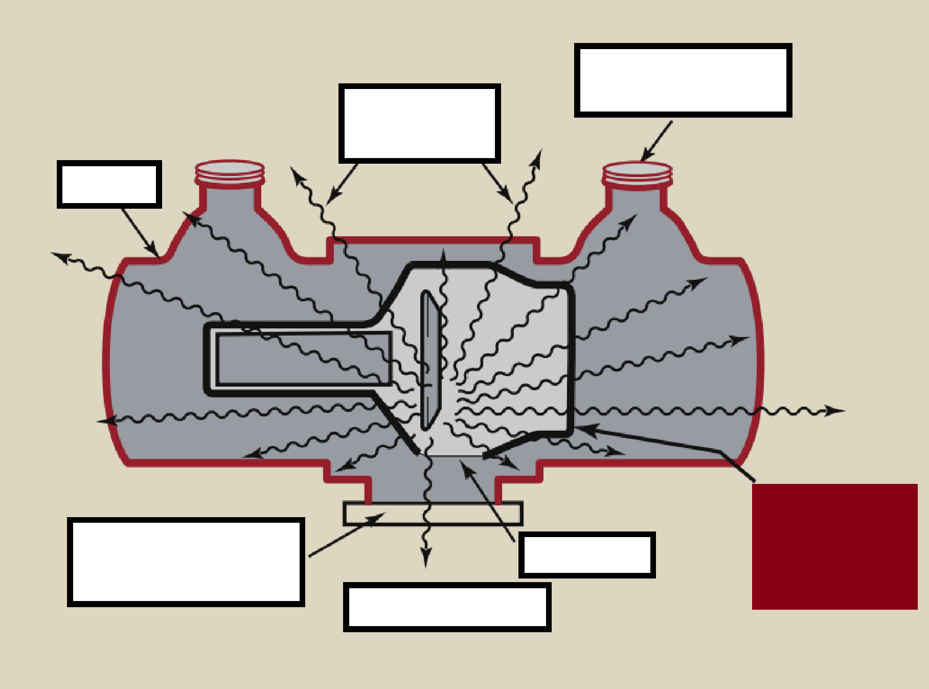
Glass or metal enclosure
Cathode
The negative side of the X-ray tube; contains the filament and focusing cup and supplies electrons
Filament
A small coil of thoriated tungsten that produces electrons when heated
Thermionic Emission
The process in which heating the filament causes electrons to be released from its surface
Thoriated Tungsten
The material commonly used for filaments; tungsten withstands high heat, while thorium improves thermionic emission and extends filament life
Focusing Cup
A negatively charged metal shroud around the filament that focuses the electron beam onto a small area of the anode
Dual-Filament Cathode
A cathode containing two filaments that produce two focal spot sizes: small and large
Small Focal Spot
A smaller focal spot used when better spatial resolution is needed; typically 0.1–1 mm
Large Focal Spot
A larger focal spot used for large body parts and high-heat techniques; typically 0.3–2 mm
Space Charge
A cloud of electrons surrounding the filament after electrons are emitted.
Space Charge Effect
The repulsion between electrons in the space charge that makes it harder for additional electrons to leave the filament.
Saturation Current
The maximum tube current reached when all available electrons from the filament are being used; increasing kVp further does not increase mA.
Emission Limited
The condition in which the X-ray tube is operating at saturation current, meaning all available electrons are being used.
Grid-Controlled Tube
An X-ray tube designed to turn X-rays on and off very rapidly; the focusing cup acts as the exposure switch.
Tube Current (mA)
The amount of electron flow from cathode to anode; controlled primarily by filament current.
Anode
The positive side of the X-ray tube; receives electrons, conducts electricity, supports the target, and dissipates heat.
Stationary Anode
An anode that does not rotate; used in dental, portable, and special-purpose units where high tube current isn't required.
Rotating Anode
An anode that rotates during exposure, spreading heat over a much larger area and allowing higher mA and shorter exposure times.
Target
The area of the anode struck by electrons from the cathode, where X-rays are produced.
Tungsten Target
The primary target material for general radiography because of its high atomic number, good thermal conductivity, and high melting point.
Anode Heat Dissipation
The ability of the anode to remove and spread the heat produced when electrons strike the target.
Anode Stem
The shaft connecting the anode to the rotor; usually made of molybdenum because it conducts heat poorly
Rotor
The component of the induction motor that rotates the anode inside the X-ray tube.
Induction Motor
The motor that uses electromagnetic forces to rotate the anode without a mechanical connection through the enclosure.
Focal Spot
The actual area of the target from which X-rays are emitted.
Actual Focal Spot
The focal spot as it appears from the image receptor; it is smaller than the actual focal spot because of the target angle.
Line-Focus Principle
Angling the anode target allows a large actual focal spot for heat while producing a small effective focal spot for better resolution.
Target Angle
The angle of the anode target; smaller target angle = smaller effective focal spot.
Heel Effect
The difference in X-ray intensity across the beam caused by greater absorption of X-rays on the anode side of the target
Cathode Side
The higher-intensity side of the X-ray beam. Place over the thicker part of the anatomy.
Anode Side
The lower-intensity side of the X-ray beam. Place over the thinner part of the anatomy.
Off-Focus Radiation
X-rays produced when electrons bounce off the focal spot and strike other areas of the target.
Effects of Off-Focus Radiation
It increases skin dose, reduces image contrast, and can expose anatomy that should have been excluded by collimation.
How to reduce Off-Focus Radiation
Reduced using a fixed diaphragm near the tube window or a metal enclosure; a grid does not reduce it.
Radiation
Transfer of heat through the emission of infrared radiation.
Conduction
Transfer of heat from one area of an object to another through the material.
Convection
Transfer of heat through the movement of a heated substance from one place to another.
Anode Heating
Most electron energy becomes heat at the anode; excessive heating can cause melting, pitting, cracking, and tube failure.
Anode Pitting
Surface damage/irregularities caused by excessive anode heating, which can reduce and vary X-ray output.
Anode Cracking
Cracking caused by the anode temperature increasing too rapidly, potentially making the rotating anode unstable and causing tube failure.
Cold Anode
An anode that has not been warmed before a high-technique exposure; maximum techniques should never be applied to a cold anode.
Anode Warm-Up
Using low-technique exposures first to gradually warm the anode before applying maximum techniques.
Rotor Bearing Damage
Excessive heat transferred to the rotor bearings increases rotational friction and imbalance, potentially causing tube failure.
Filament Failure
Excessive filament heating causes more tungsten vaporization and can make the filament wire thinner until it breaks.
Open Filament
A filament that has broken, preventing electron production; similar to a burned-out light bulb filament.
Electron Arcing
An electrical discharge from the filament to the enclosure, often caused by vaporized tungsten; the most frequent cause of abrupt tube failure.
Tungsten Vaporization
Tungsten atoms vaporize from the filament and anode, coating the enclosure and potentially disturbing the tube's electrical balance.
Safe Area — Rating Chart
For a selected mA, combinations of kVp and time below the curve are safe.
Anode Cooling Chart
Shows the anode's heat capacity and cooling time after exposure.
Housing Cooling Chart
Shows the heat capacity and cooling time of the X-ray tube housing.
Single-Phase Heat Units
HU = kVp × mA × seconds.
Three-Phase/High-Frequency Heat Units
HU = 1.4 × kVp × mA × seconds.
Heat Unit → Joule
1 HU = 1.4 J for three-phase/high-frequency equipment.
Joule → Heat Unit
1 J = 0.7 HU for three-phase/high-frequency equipment.