Computerized Tomography
 Call Kai
 Learn
Learn Practice Test
 Spaced Repetition
 Match
Match Flashcards
 Knowt Play
1/36

There's no tags or description
Looks like no tags are added yet.
Name | Mastery | Learn | Test | Matching | Spaced | Call with Kai | Chat |
|---|
No analytics yet
Send a link to your students to track their progress
37 Terms
1st CT Scanner
two slice NaI detetor withh 80×80 image matrix and 8 shades of gray
1st generation of CT
rotate/translate tube and detectors
two NaI detectors
5 minute acquisition time
2nd generation of CT
rotate/translate
an array of detectors
narrow fan beam
one minute acquisition time
3rd generation of CT
rotate/rotate
wide fan beam
1-2 second image acquisition
bow-tie filter was used to equalize image noise for varying thickness body parts
4th generation of CT
rotate/stationary (only x-ray tube rotates)
1-2 seconds per scan
found to have a wobble artifact due to detectors and x-ray sources on independent axes
modern CT
helical scanning
slip-ring technology - allows continuous rotation
multidetector array (4-320 channels of spatial data)
modern CT most closely resembles the 3rd generation
Ray
a single transmission measurement thru a patient made by a single detectora
projection (or view)
series of rays that pass thru the patient at the same orientation
Sinogram
projections are stored for each angular orientation in data file
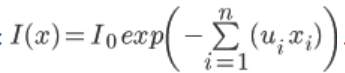
intensity formula
assuming homogeneous, monoenergetic, narrow beam geometry
iterative solution
approximate solution to linear attenuation coefficients of each voxel by guessing at them and then adjusting using an algorithm until result matches closely with measured
high computational demands (in modern tech)
Improved image quality
backprojection
process begins by taking our ray projection and backprojecting the result along the ray-line
take our projection data, smear it back along project path evenly - leaving a blurring artifact (fix with filtering)
convolution
process of applying a reconstruction kernel to account for the backprojection blur
filtered backprojection
leads to streaking artifacts around high Z materials when there is complete attenuation of the beam
Analytical algorithms
solve all equation for unknown attenuation coefficients
too much for our current computing power
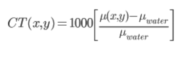
CT numbers (HUs)
Air CT number
-1000
lung ct number
-300
fat ct number
-90
water ct number
0
white matter ct number
30
gray matter ct number
40
muscle ct number
50
bone ct number
1000 (up to 3000 for dense bone)
titanium ct number
5000
CT number use in radiotherapy
used for heterogeneity corrections in dose calculations
- attenuation coefficients can be related to electron density to correct dose distributions (aka using CT numbers)
electron density to HU calibration curve
created by scanning a phantom of known electron density
plot CT number verses electron density
considerations for scanning phantom
energy
location
how much does a change in HU affect the dose calculation?
depends on exactly how much of the material with a different HU values are present
rule of thumb: 10% change in HU value yields a 2% change in calculated dose
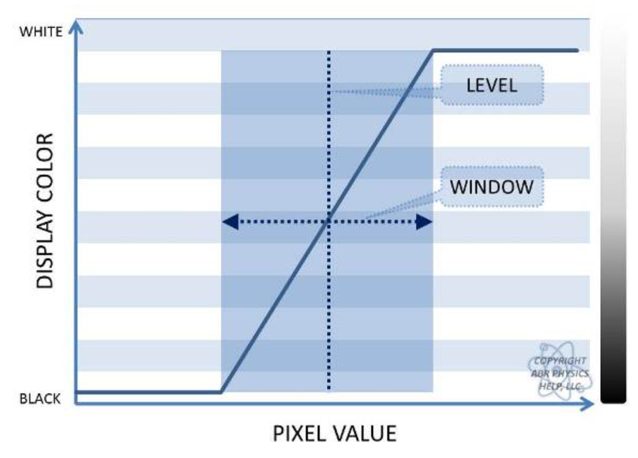
window width
determines contrast of image
change the gradient from black to white
level
is the ct number at the center of the window
Pitch
Pitch = table increment per rotation (mm) /Beam collimation
pitch = 1
we gather similar information a contiguous axial scan
pitch < 1
implies overlapping slices (higher dose and increased image quality)
pitch > 1
implies gaps between slices (reduced dose and decreased image quality)
Cone beam CT
slow - about 60 seconds
lower quality than a scan compared to CT due to large field generating a lot more scatter that degrades image quality
CT detectors
most use solid-state scintillators
CdWO_4 (Cadmium Tungstate), Gadolinium Based, Proprietary Ceramic Scintillator