[3] Hardwired Relay Logic Technology
 Call Kai
 Learn
Learn Practice Test
 Spaced Repetition
 Match
Match Flashcards
 Knowt Play
1/60

There's no tags or description
Looks like no tags are added yet.
Name | Mastery | Learn | Test | Matching | Spaced | Call with Kai | Chat |
|---|
No analytics yet
Send a link to your students to track their progress
61 Terms
Relay logic
a control system using electromechanical relays and wired connections
Relay logic
used before PLCs
Relay
Input Devices
Output Devices
Components of Relay Logic Systems
Relay
an electromechanical switch made up of an electromagnet and a set of contacts
Relay
allows a low-power electrical circuit to control a higher-power circuit
Coil
Armature
Contacts
Spring
Frame/Base
Relay Parts
Coil
relay part pertaining to a wire wound around a core that generates a magnetic field when energized; this magnetic field is responsible for moving the relay’s internal mechanical parts
Armature
relay part pertaining to a movable metal lever that is attracted by the magnetic field when the coil is energized
Armature
relay part that physically moves the contacts to either open or close the circuit
Contacts
relay parts pertaining to metal connections that either complete (closed) or interrupt (open) the electrical circuit; normally open, normally closed, common terminal
Spring
relay part that returns the armature to its original position when the coil is deenergized
Frame/Base
relay part pertaining to the physical structure that holds all the parts together
Electromagnetic Relay
Solid State Relay
Timer Relay
Types of relay
Electromagnetic relay
common and basic industrial relay
Solid state relay
a type of relay that uses semiconductors instead of mechanical parts
Timer relay
a type of relay that introduces a delay before switching
SPST (Single Pole Single Throw)
SPDT (Single Pole Double Throw)
DPST (Double Pole Single Throw)
DPDT (Double Pole Double Throw)
Types of relay based on the number of contacts
SPST (Single Pole Single Throw)
a type of relay containing 1 common terminal and 1 NO or NC terminal
SPDT (Single Pole Double Throw)
a type of relay containing 1 common terminal, 1 NO terminal, and 1 NC terminal
DPST (Double Pole Single Throw)
a type of relay containing 2 common terminals and 2 NO or NC terminals
DPDT (Double Pole Double Throw)
a type of relay containing 2 common terminals, 2 NO terminals, and 2 NC terminals
RELAY SPECIFICATIONS"
Coil Voltage
Coil Power
Contact Configuration
Contact Voltage Rating
Contact Current Rating
Switching Time
Relay specifications
Coil Voltage
relay specification pertaining to the required voltage to energize the relay coil; common values: 5V, 12V, 24V, 48V, 110V, 220V (DC or AC)
Coil Power
relay specification pertaining to the power required to operate the relay
Contact Configuration
relay specification pertaining to the number of pole and throw (SPST, SPDT, DPDT, 4PDT, etc.)
Contact Voltage Rating
relay specification pertaining to the maximum voltage that the contacts can switch safely; expressed in volts (DC or AC)
Contact Current Rating
relay specification pertaining to the maximum current that the relay contacts can handle; expressed in amperes
Switching Time
relay specification indicating the operate time and the release time
Operate Time
under switching time, this is the time required to activate the contacts
Release Time
under switching time, this is the time required to deactivate the contacts
Input Devices
these are devices that are connected to the relays in the circuit to act as inputs; include switches, push buttons, and sensors
Output Devices
devices that are connected to the relays in the circuit to act as outputs; include indicator lights, solenoids, motors, contactors, buzzers, and horns
Ladder Diagram
a symbolic representation of an electrical circuit using horizontal rungs and vertical rails
Rung
each represents a control action, such as starting a motor, turning on a light, or activating a relay
Ladder Diagram
used in relay-based systems and Programmable Logic Controllers (PLCs)
Relay Coil
What does this ladder diagram symbol represent?

Normally open relay contact
What does this ladder diagram symbol represent?

Normally closed relay contact
What does this ladder diagram symbol represent?

Normally open push button
What does this ladder diagram symbol represent?

Normally closed push button
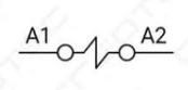
What does this ladder diagram symbol represent?

Solenoid valve
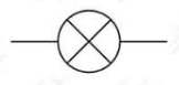
What does this ladder diagram symbol represent?
Pilot light
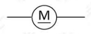
What does this ladder diagram symbol represent?
Motor
What does this ladder diagram symbol represent?
Buzzer
What does this ladder diagram symbol represent?

Momentary
means that the contacts are actuated when pressed but will return to the initial state when released
Indicator lights
mall visual signaling devices used in relay logic circuits to indicate the status of a machine, process, or electrical system
Red
pilot light meaning fault, stop, emergency
Green
pilot light meaning normal operation, running
Yellow/Amber
pilot light meaning warning, caution, standby
Blue
pilot light meaning special condition, operator attention needed
White
pilot light meaning general system active, power on
Voltage Rating
Current Consumption
Mounting Type
Color Coding
Durability & Protection (IP Rating)
Pilot Lamp Specifications
Voltage rating
a pilot lamp specification that must match the system voltage (24V DC, 110V AC, 220V AC)
Current consumption
a pilot lamp specification where LED lamps are pertained as more energy-efficient
Mounting type
a pilot lamp specification that may be a panel mount, screw-type, or push-fit
Color coding
a pilot lamp specification wherein proper color standards for system status must be ensured
Durability & Protection (IP Rating)
a pilot lamp specification wherein industrial environments require IP65/IP67-rated lamps for dust/water resistance
On/Off-delay Circuit
a type of relay circuit that has an on or off delay coil wherein the set of contacts changes status depending on the set delay in the timer
On-delay
set of contacts change status after the set delay
Off-delay
set of contacts change status instantly but return to its initial state after the set delay