MOD 6 - Grid and Scatter Reduction
1/48
There's no tags or description
Looks like no tags are added yet.
Name | Mastery | Learn | Test | Matching | Spaced | Call with Kai |
|---|
No analytics yet
Send a link to your students to track their progress
49 Terms
Scatters’ influence on IQ
degrades contrast resolution by creating a “fog“ as they do not accurately represent the internal structure of the object, since they come from different paths directly from the source
scatter vs. blur
blur: sharpness/detail, magnification, distortion
scatter: exposure, subject contrast, level of noise
Three factors that contribute to scatter production
kV selection
collimated field size
density of anatomy
Effect of increased kV
increased photon energy causes
decreased photoelectric absorption AND Compton interactions BUT Compton scatter decreases less → produced compton scatter has more energy to reach the detector
increased energy causes produced scatter to have a higher chance of reaching the receptor
effects of tissue density
as tissue density increases → the chance of photon and matter interaction increased → increased scatter production
effects of field size
as field size increases → more tissue area is exposed to radiation → more tissue interaction → more scatter generation
how to reduce the effect of field size
using collimation
Grid design
wrapped in Al casing
consisted of fine lead strips that absorb scatter xrays; placed // and spaced evenly
interspace between lead strips made of radiolucent materials (Al or plastic fiber material)
Function of Grid
absorb scattered photons while allowing transmitted and mildly off focus scatter photons before the receptor → improves image contrast
Consideration of Grid Usage and PT Safety
grids will also absorb useful beams, therefore we need to increase our exposure factor to compensate for the lost useful beams → which increases PT dose
Types of Grids
parallel
focused
crossed
oscillating
Parallel / Linear Grid Construction
spaced out, vertically orientated lead strips
Parallel / Linear Grid Usage
for smaller body parts (eg. hip joint)
grid cut off
when some useful photons are absorbed by the grid because of the diverging beam, more prominent on the sides
how to reduce grid cut off
reduce beam divergence
increase SID
tight collimation
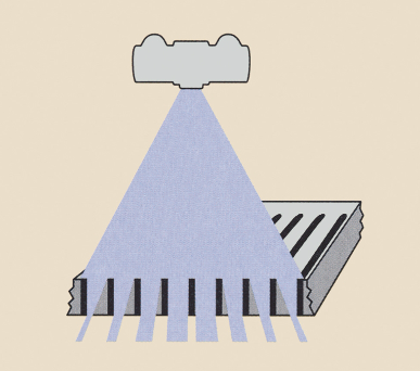
Focused Grid Design / Function
lead strips are aligned to the path of the divergent beam reducing grid cut off
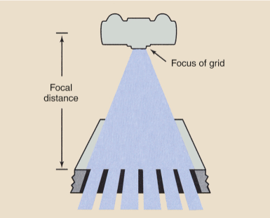
Considerations when using Focused Grids
use recommended SID = focal range/distance
CR has to be centered to the centre of the grid
Crossed Grid Design
two parallel grids stacked on top of each other
Crossed Grid Function
effective at reducing scatter therefore improved IQ, but still exhibit grid cutoff at the periphery (like parallel grids)
Crossed Grid Disadvantage
substantial technique increase, therefore not commonly used in radiography
Oscillating Grids Design / Function
either parallel or focused design within a motorized case that jiggles the grid during the exposure to improve scatter absorption while simultaneously blurring the appearance of grid lines
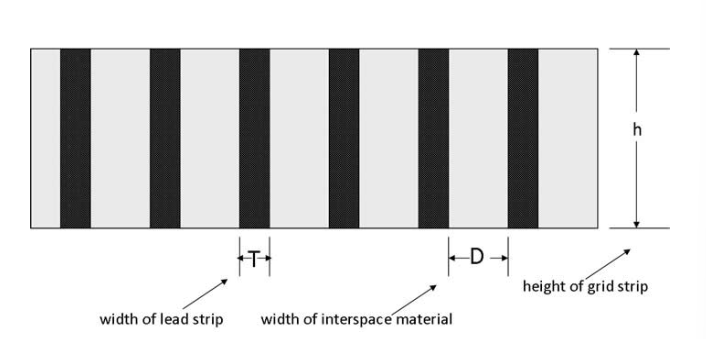
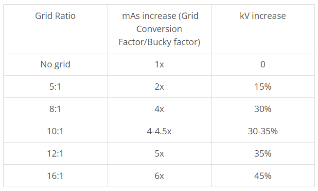
Grid Ratio
shows us how much scatter radiation absorbing ability a grid has (greater h / higher ratio = more lead strips = more absorption)
h (height) / D (distance)
Higher Grid Ratio increases
scatter absorption
PT exposure
potential for grid cut off
Grid Frequency
considers the number of lead strips per inch or cm
Higher grid frequency means and will cause
decreased interspace width → lead strips becomes closer → increased useful beam absorption → increased exposure factors → increased PT dose
Grid Conversion Factor Formulas
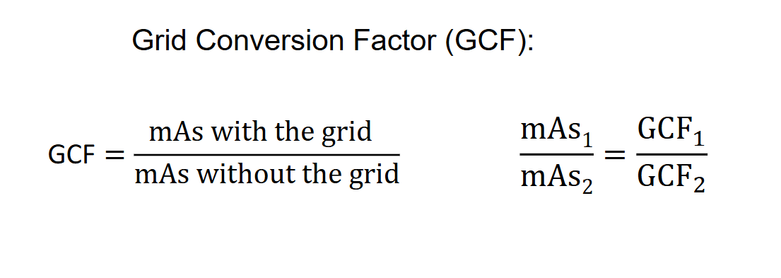
GCF Chart with Grid Ratios
Types of Grid Errors
grid cut off
grid lines
6 Ways Grid Errors Occurs
inherent
off-level
off-center
off-focus
backwards grid
grid lines
Inherent Grid cut off and how to reduce effect
occurs at the periphery of parallel grids when collimation is opened to the maximum field width
reduce effect by
reducing beam divergence
replace parallel grid with focused grid
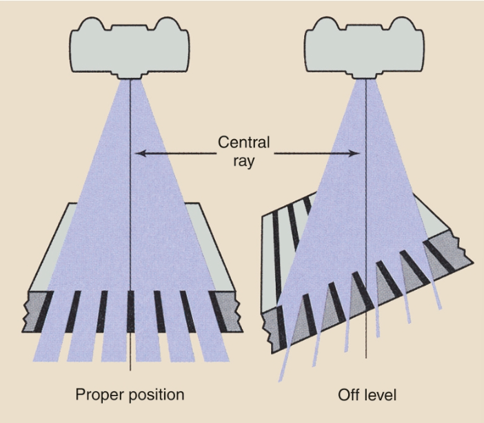
Off-level and how to reduce effect
occurs when the grid is tilted or off-level resulting in majority of the useful beam being absorbed
hence, portable grids MUST be perpendicular to the CR
Off-center and how to reduce effect
occurs when the grid is off-center causing grid cut off
ensure that the CR is ALIGNED and CENTERED to the grid
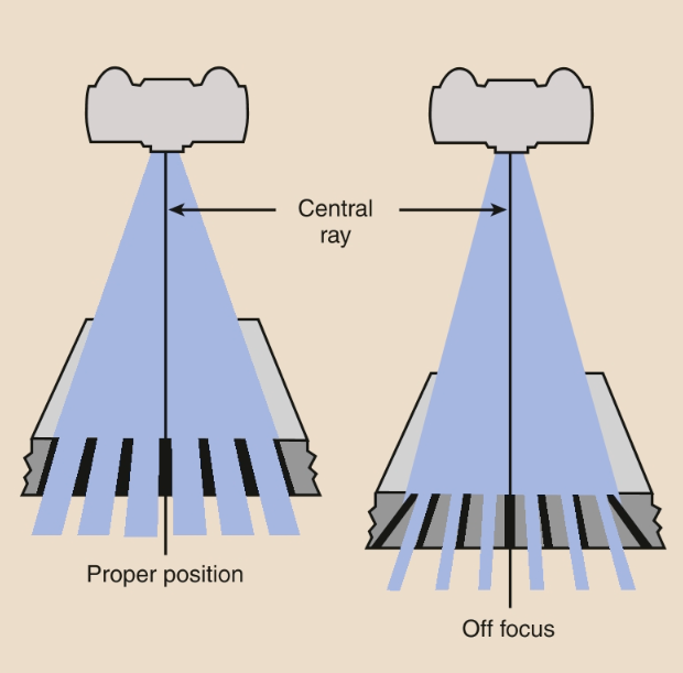
Off-focus and how to reduce effect
occurs when the incorrect SID (focal range) is applied to a focused grid causing major grid cut-off
ensure correct focal range is applied
Backwards Grid and how to reduce effect
occurs when portable focused grid is applied backwards → near complete image cut off due to opposing angles of the divergent beam and the focused grid lines
ensure grid is not on backwards
Grid Lines and how to reduce this effect
inherent grid artifacts when using a portable grid as there is no oscillating or reciprocating mechanism that serves to blur the distinct lines
not much can be done to eliminate these lines
Field of View (FOV) on CR/DR
FOV on CR/DR is the component of the whole imaging plate
Significance of FOV
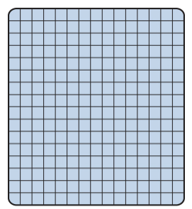
allows us to determine the Pixel size
Pixel Size Formula / Calculations
Pixel size = Fixed FOV/Matrix Size
Fixed FOV = CR plates whole size
Matrix Size = pixel area arrangement
Pixel size = micron size pixel that can be displayed
Visualized field of view
also known as the collimated field; the changing field of view when collimating
Pixel size and image distortions
define pixels in our receptor image are being redistributed across the corresponding pixels in the monitor when displayed, causing our original image to visually magnify if a smaller image size (finger) is being displayed onto a large monitor, and vice versa
Collimators / X-ray Beam Restrictions Function
to decrease the field that a patient is being exposed to
acts as an added filtration for the x-ray beam
Old xray beam restriction designs
cylindrical or cone shaped metallic structures added to the base of the x-ray tube
Modern xray beam restriction designs
collimator box added to the x-ray housing's port hole
Collimator Composition
several sets of lead shutters (controllable with external knobs)
light bulb
mirror
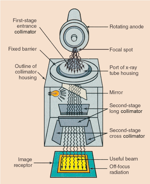
Effects of Multiple layers of collimators
helps with the image sharpness
gives multiple possibilities to reduce the amounts of off-focus radiation from reaching the patient
Effects of Collimation
lowers exposed field on PT and receptor
increases visual quality of images as it reduces field size
reduces noise
Buffer region
2.5cm region around the edge of the interested region that should be included to compensate for the misalignment of the collimator lightbox
Positive Beam Limitation (PBL)
sensor systems that determine the size of a cassette (if CR) and limit the collimator from expanding beyond the border sizes of the imaging plate
PBL and Collimation
regardless of PBL, collimation should still ALWAYS be done manually by the tech as per our SC35 safety code manual from Health Canada