Energy Systems 244 - Week 3 to 4 - 3.2 to 3.7
 Call Kai
 Learn
Learn Practice Test
 Spaced Repetition
 Match
Match Flashcards
 Knowt Play
1/29

There's no tags or description
Looks like no tags are added yet.
Name | Mastery | Learn | Test | Matching | Spaced | Call with Kai | Chat |
|---|
No analytics yet
Send a link to your students to track their progress
30 Terms
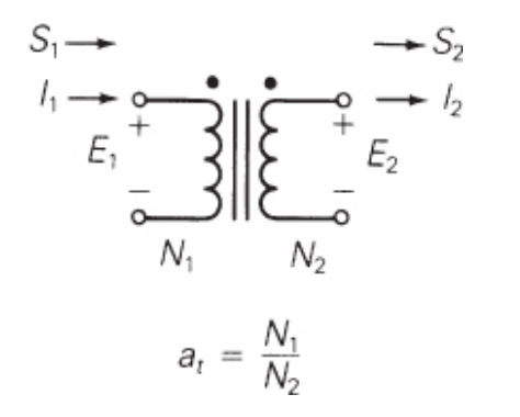
Draw a sketch of an ideal transformer
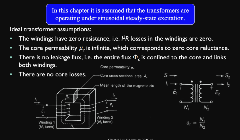
State the assumptions made about ideal transformers
Windings have zero resistance
I² losses in the windings = 0
Core permeability, μc is infinite
zero core reluctance
There is no leakage flux
The entire flux Φc is confined to the core and links both windings
There are no core losses
Describe what is meant by permeability
The ability of a material to concentrate magnetic flux lines more easily
Describe Ampere’s Law
The magnetic flux density around a closed loop is proportional to the total electric current passing through that loop
∫Bdl=μcIenclosed
B = Magnetic flux density
μc = permeability of the core
Ienclosed = net current enclosed by the loop
Hc=μcB
∫Htandl=Ienclosed
Ienclosed=N∗I
N = number of turns
I = current flowing through each turn
I_{enclosed} = N \dot
Use Ampere’s laws to derive an ideal transformer relationship
Hclc=N1I1−N2I2 (1)
Bc=μcHc [Wb/m²] (2)
Φc=BcAc [Wb] (3)
Sub (2) and (3) into (1):
N1I1−N2I2=μcAclcΦc (4)
Core reluctance Rc=μcAclc (5)
sub (5) into (4)
N1I1−N2I2=RcΦc (6)
since μc is infinite, Rc tends to zero thus:
N1I1−N2I2=0
N1I1=N2I2 (7)
∴N2N1=I2I1 (8)
![<ul><li><p>$$H_c l_c = N_1I_1 - N_2I_2$$ (1)</p></li><li><p>$$B_c = \mu_cH_c$$ [Wb/m²] (2)</p></li><li><p>$$\Phi_c = B_cA_c$$ [Wb] (3)</p></li><li><p>Sub (2) and (3) into (1):</p><ul><li><p>$$N_1I_1-N_2I_2=\frac{l_c}{\mu_cA_c}\Phi_{c}$$ (4)</p></li></ul></li><li><p>Core reluctance $$R_c = \frac{l_c}{\mu_cA_c}$$ (5)</p></li><li><p>sub (5) into (4)</p><ul><li><p>$$N_1I_1 - N_2I_2 = R_c\Phi_c$$ (6)</p></li></ul></li><li><p>since $$\mu_c$$ is infinite, $$R_c$$ tends to zero thus:</p><ul><li><p>$$N_1I_1 - N_2I_2 = 0$$ </p></li><li><p>$$N_1I_1 = N_2I_2$$ (7)</p></li></ul></li><li><p>$$\therefore \frac{N_1}{N_2} = \frac{I_1}{I_2}$$ (8)</p></li></ul><p></p>](https://assets.knowt.com/user-attachments/c9e6d318-3f98-4f6c-8548-4500a620ec0b.png)
Describe Faraday’s Law
Voltage induced is proportional to the rate of change of flux ϕ
e(t) = Ndtdϕ(1)
Use Faraday’s law to derive ideal transformer relationships
We now do the following:
assume the rate of change is a sinusoidal-steady-state flux with constant frequency, ω
Represent e(t) and ϕ as phasors, E and Φ
thus, (1) becomes:
E = N(jω)Φ (2)
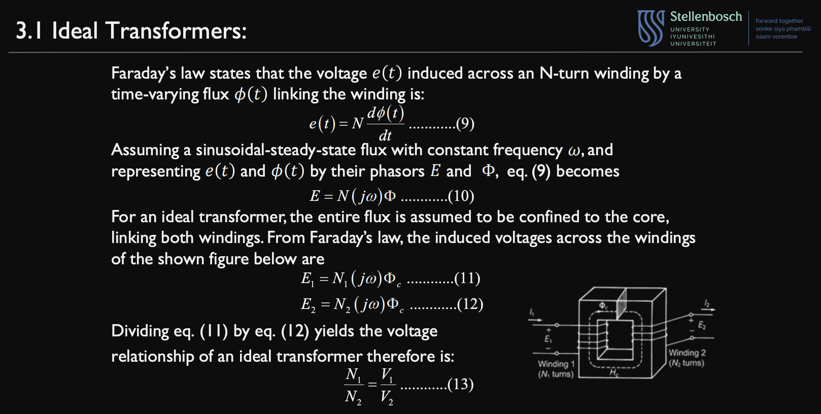
For an ideal transformer, the entire flux is confined to the core, thus:
E1=N1(jω)Φc (3)
E2=N2(jω)Φc (4)
Dividing (3) by (4) gives us:
V2V1=N2jωN1jω
V2V1=N2N1 (5)
Use both Faraday’s Law and Ampere’s Law in order derive relationship equations for:
EMF
Current
Impedance
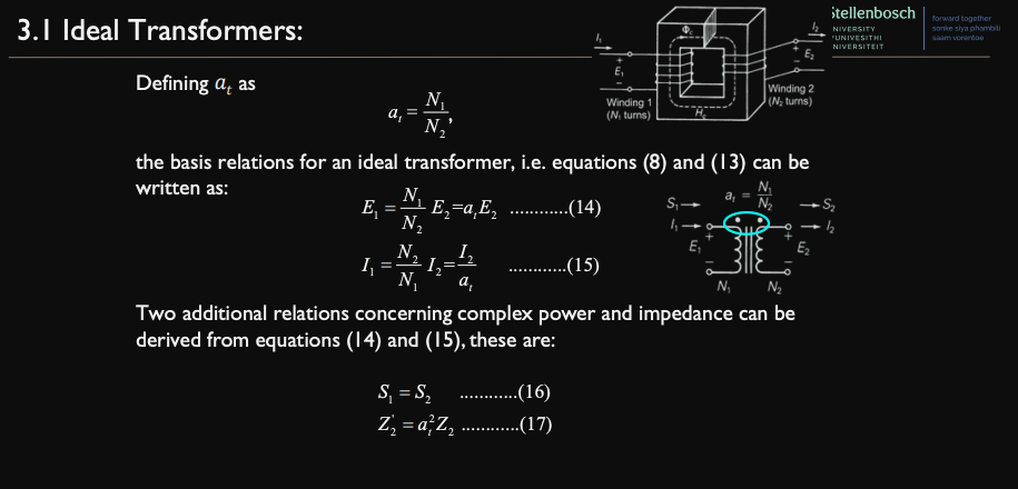
we say
at=N2N1
∴
E1=N2N1⋅E2 ….(1)
I2=N1N2⋅I2=atI2 …(2)
Thus:
S1=S2 …(3)
Z’2=a2Z2 …(4)
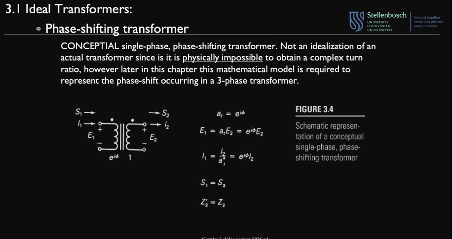
Describe the phase shifting transformer:
Definition
at
EMF
Current
Complex power
Impedance
single phase
at=ejϕ
E1=atE2=ejϕ⋅E2
I1=a∗tI2=ejϕ⋅I2
S1=S2
Z’2=Z2
State the properties of a practical transformer
Windings have resistances
Core permeability is finite
Magnetic flux is not all confined to the core
There are real and reactive losses in the core
Draw a sketch of a practical transformer

For a practical transformer, describe the winding resistances
Represent the resistance of the conductors used to turn the respective windings
accounts for real power loss I²R in the windings

For a practical transformer, describe the leakage reactances
there are leakage fluxes that come from the windings
they cause a voltage drop
accounts for reactive power loss I²X

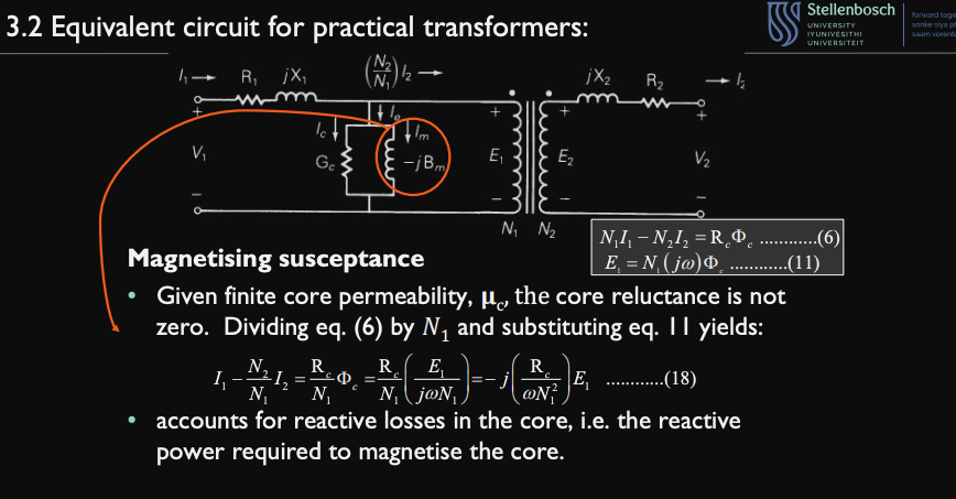
For a practical transformer, describe the magnetising susceptance
since core permeabilityμc is finite,
core reluctance ≠ 0
N1I1−N2I2=RcΦc …(1)
E1=N1(jω)Φc …(2)
divide (1) by N1 and sub (2):
I1−N1N2I2=N1RcΦc
=N1Rc(jωN12E1)E1
=−j(ωN12Rc)E1
Accounts for reactive losses in core
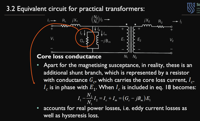
For a practical transformer, describe the Core loss conductance
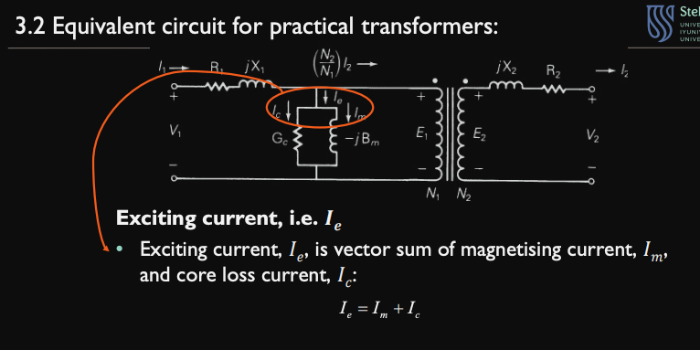
There is an additional (shunt) branch along with the magnet susceptance branch with resistance Gc
It carries core loss current Ic
Ic is in phase with E1
Accounts for real power losses
eddy current losses
hysteris loss
For a practical transformer, describe the exciting current
Ie
Ie=Im+Ic
Im=magnetisingsusceptance
Ic= Core loss conductance
Describe what is meant by nameplate data
the rated voltages and power
Describe what is meant by the open circuit test
rated voltage is applied to primary with secondary open
measure the primary current and losses
Determine shunt admittance of winding 1
Ym=Gc−jBm
neglect series impedance
Describe what is meant by the short circuit test
short the secondary
apply voltage to the primary and obtain rated current flow
measure voltage and losses
determine series impedance referred to winding 1
Zeq1=Req1+jXeq1
neglect shunt admittance
Describe the Per unit system
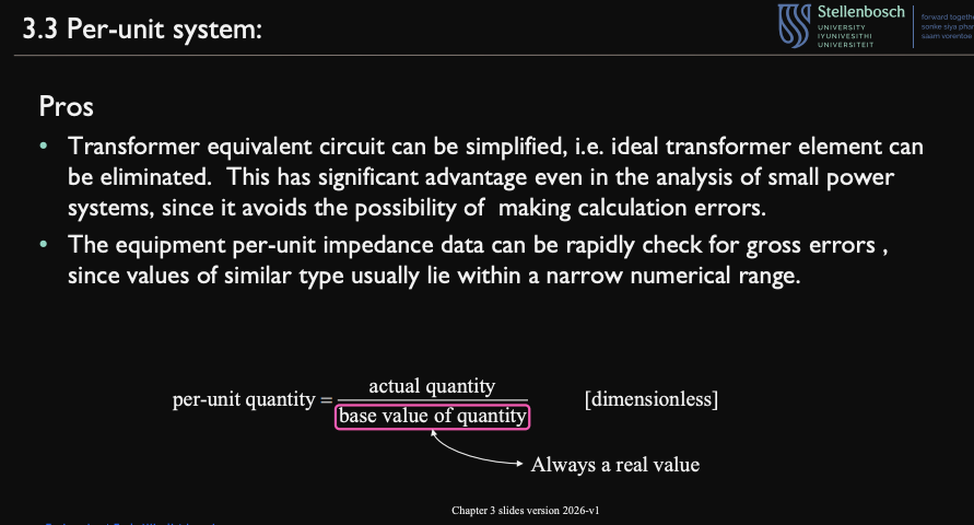
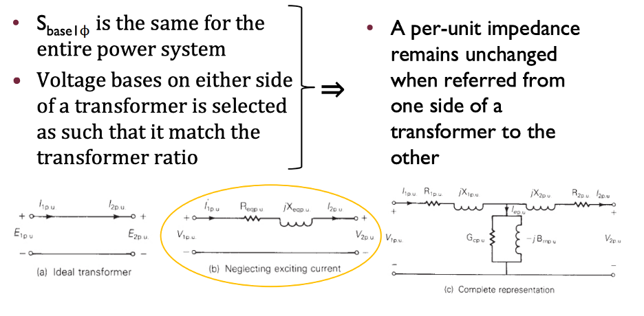
The transformer equivalent circuit can be simplified
the ideal transformer element is eliminated
State the per unit system formula
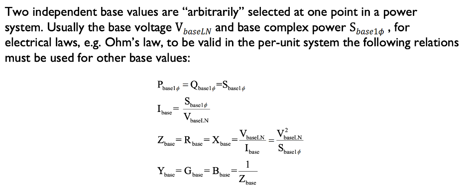
per−unit quantity=base value of quantityactual quantity
it is dimensionless
base value of quantity is always a real value
Describe the per unit system
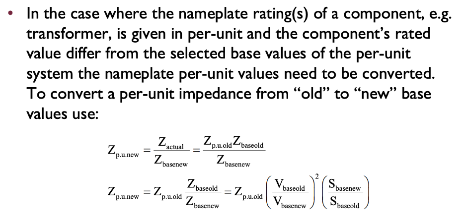

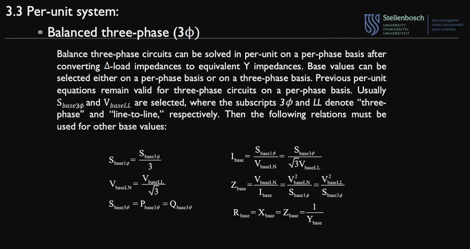
Describe the balanced 3 phase circuit
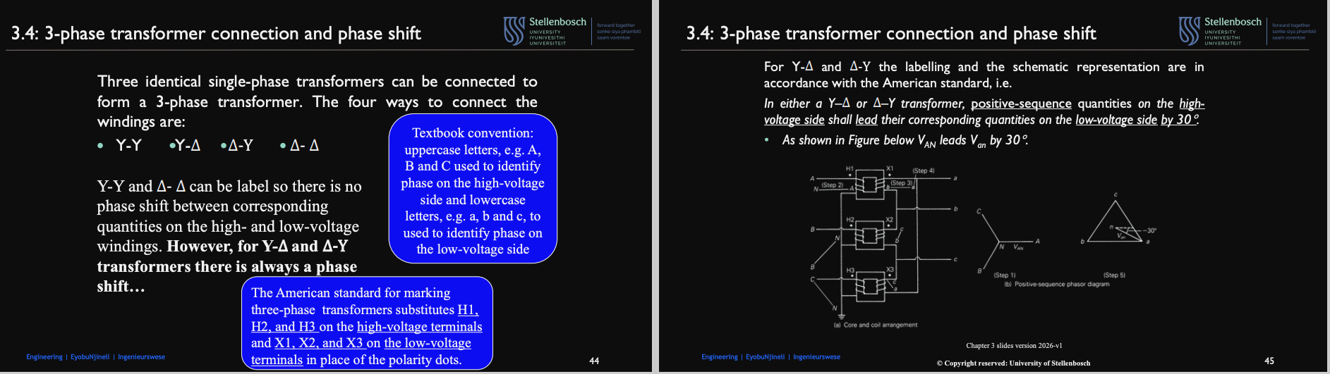
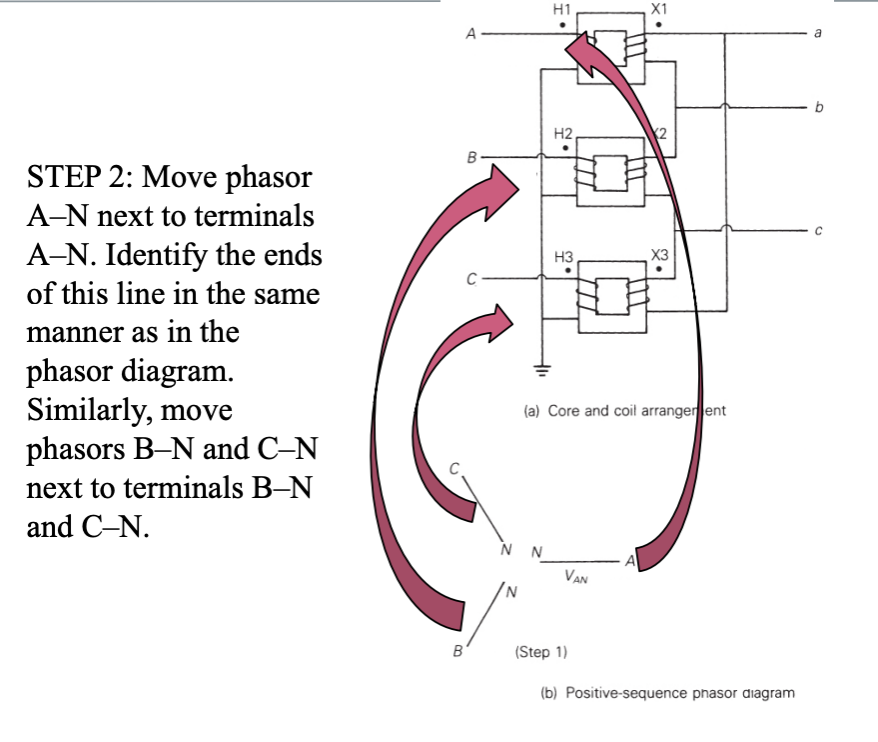
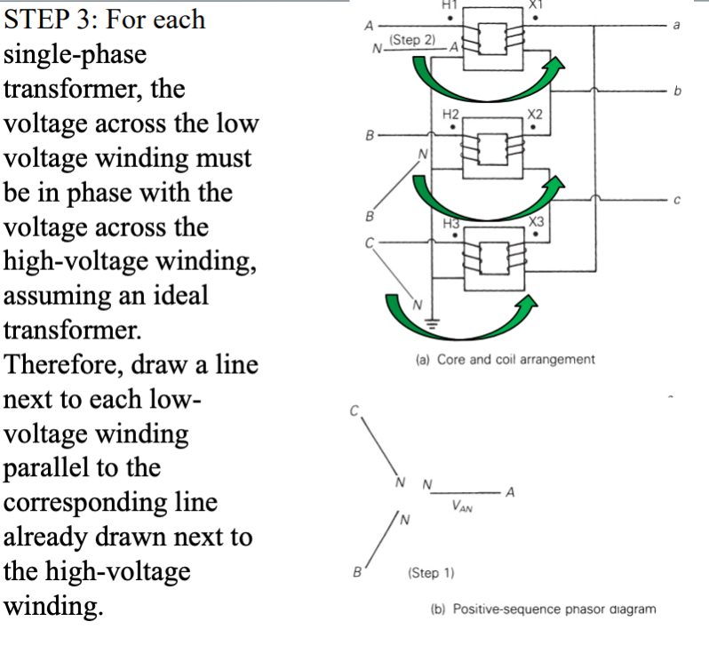
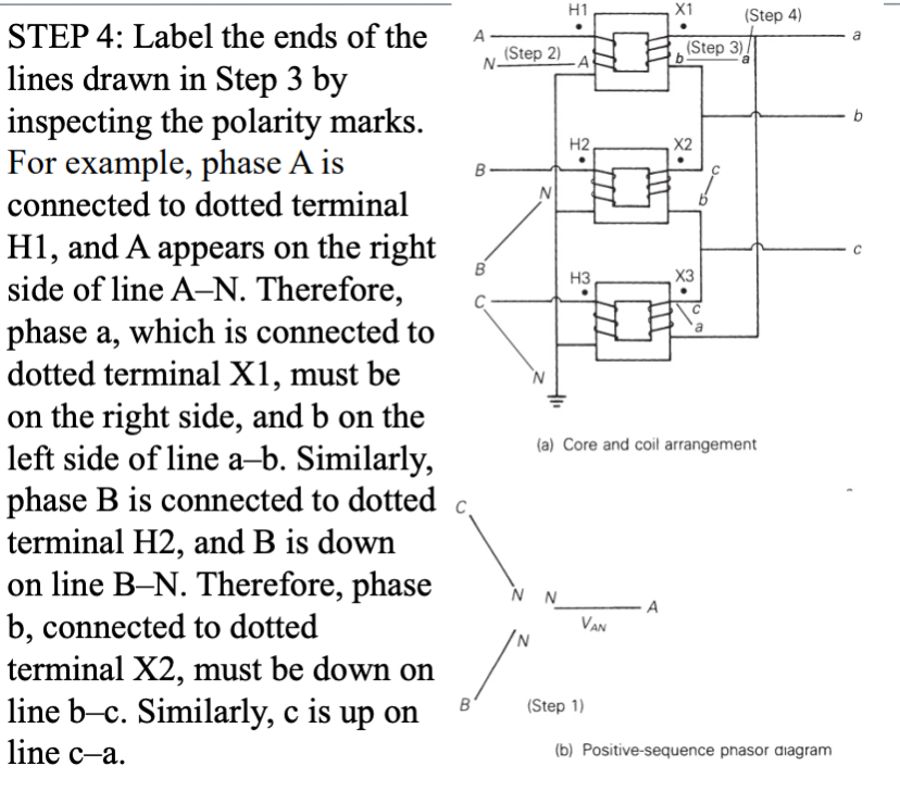
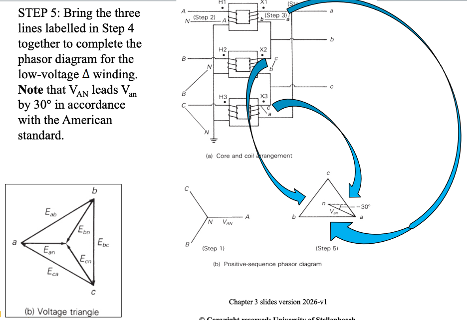
Describe the 3 phase transformer connection and phase shift
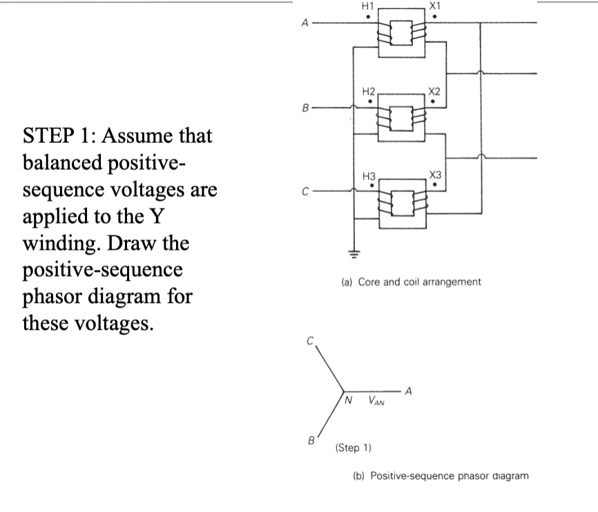
Describe the steps for converting a 3-phase transformer
Describe the advantages of the delta winding

Describe the convention for selecting base values of a balanced 3-phase 2-winding transformers


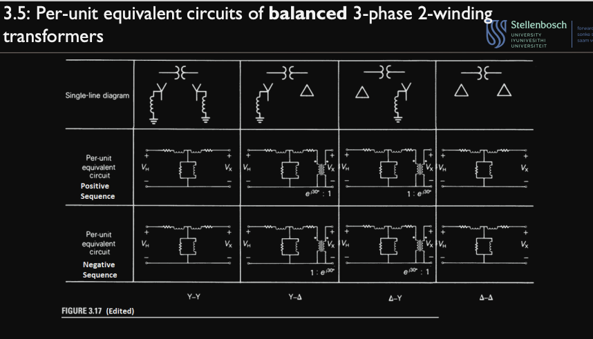
Sketch the Per-unit equivalent circuits positive and negative sequences of the following single line diagrams:
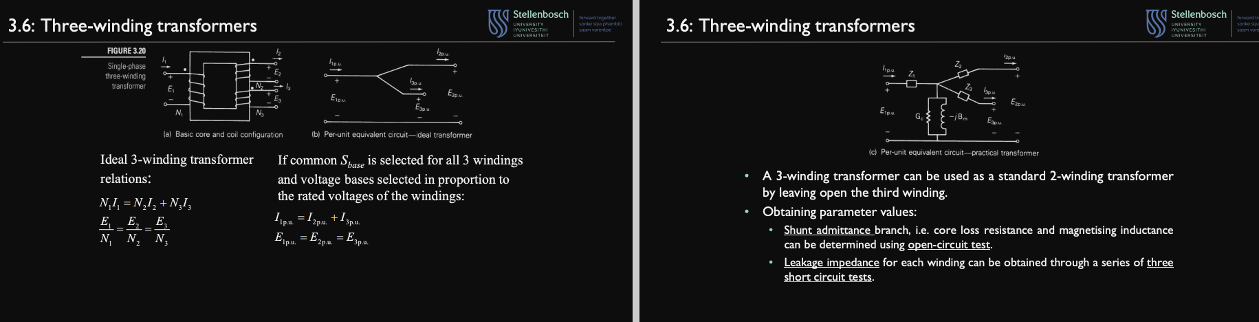
Describe 3-winding transformers
Describe the advantages and disadvantages of a autotransformers