2. Design Principles, Pontic Design & Alternative Connector Design ✅
 Call Kai
 Learn
Learn Practice Test
 Spaced Repetition
 Match
Match Flashcards
 Knowt Play
1/38

There's no tags or description
Looks like no tags are added yet.
Name | Mastery | Learn | Test | Matching | Spaced | Call with Kai | Chat |
|---|
No analytics yet
Send a link to your students to track their progress
39 Terms
Factors Influencing Design Principles
1. Crown-to-Root Ratio
How much tooth sits above the bone vs. embedded in it.
2. Root Configuration
Shape and spread of the root(s) supporting the abutment.
3. Periodontal Ligament Area
Root surface area available to bear functional load.
4. Biomechanical Considerations
How span length and pontic width affect flexure.
5. Path of Insertion
The shared line of draw the restoration seats along.
Crown-to-Root Ratio
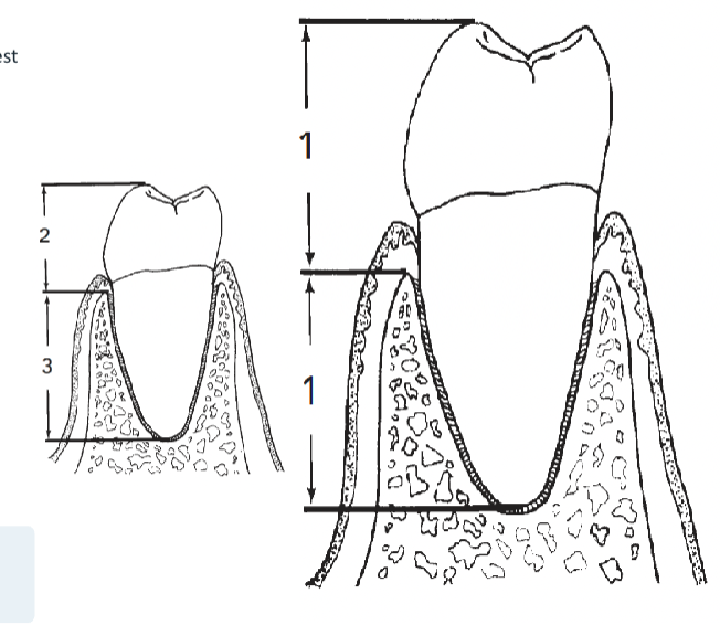
The crown-root ratio compares the length of tooth occlusal to the alveolar crest of bone with the length of root embedded in bone.
As alveolar bone moves apically, the lever arm of the portion out of bone
increases — raising the chance of harmful lateral forces
2:3 is the optimum crown-root ratio for a fixed partial denture abutment.
1:1 is the maximum ratio acceptable under normal circumstances
Root Configuration
an important part of assessing an abutment's suitability from a periodontal
standpoint.
Multirooted posterior teeth with widely separated roots offer better periodontal support than roots that converge, fuse, or present a conical configuration.
Example: the maxillary premolar, despite similar root surface area, is a superior abutment to the maxillary central incisor because of its greater faciolingual root dimension.
Periodontal Ligament (PDL) Area
The PDL area — the surface area of root attached to bone — is a key factor in evaluating a prospective abutment.
Larger teeth have greater PDL surface area and can bear more added stress.
The pontic span that can be restored is limited, in part, by the abutment teeth's ability to accept that additional load
Periodontal Ligament Area — Ante's Law
The root surface area of the abutment teeth must equal or surpass that of the teeth being replaced by the pontic.
By this premise, one missing tooth can be successfully replaced if the abutment teeth are healthy
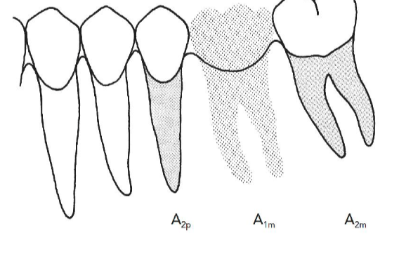
Applying Ante's Law: Two Missing Teeth
If two teeth are missing, a fixed partial denture can probably still replace them — but the limit is being approached.
When the combined root surface area of the abutments is only just equal to that of the teeth being replaced, a generally unacceptable situation exists
ex of 2 missing teeth
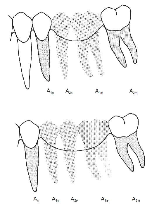
Case 1: premolar + second molar ≈ the teeth being replaced — acceptable.
Case 2: canine + second molar is exceeded by the teeth being replaced — a poor choice of abutments.
D E S I G N P R I N C I P L E S · 4
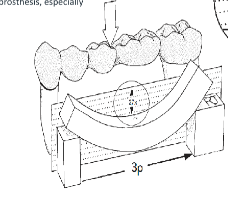
Biomechanical Considerations — The Cube Law
Increased load on the periodontal ligament from a long-span fixed partial
denture makes longer spans less rigid.
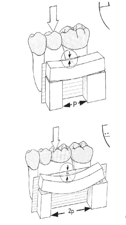
Bending (deflection) varies directly with the cube of the span length, and
inversely with the cube of the pontic's occlusogingival thickness.
Compared with a single-tooth pontic span, a two-tooth pontic span will bend 8 times as much.
A three-unit pontic will bend 27 times as much as a single pontic.
A long-span fixed partial denture on short mandibular teeth can therefore
produce disappointing results.
Longer pontic spans also increase torquing forces on the prosthesis, especially at the weaker abutment
D E S I G N P R I N C I P L E S · 5
Path of Insertion — Definition
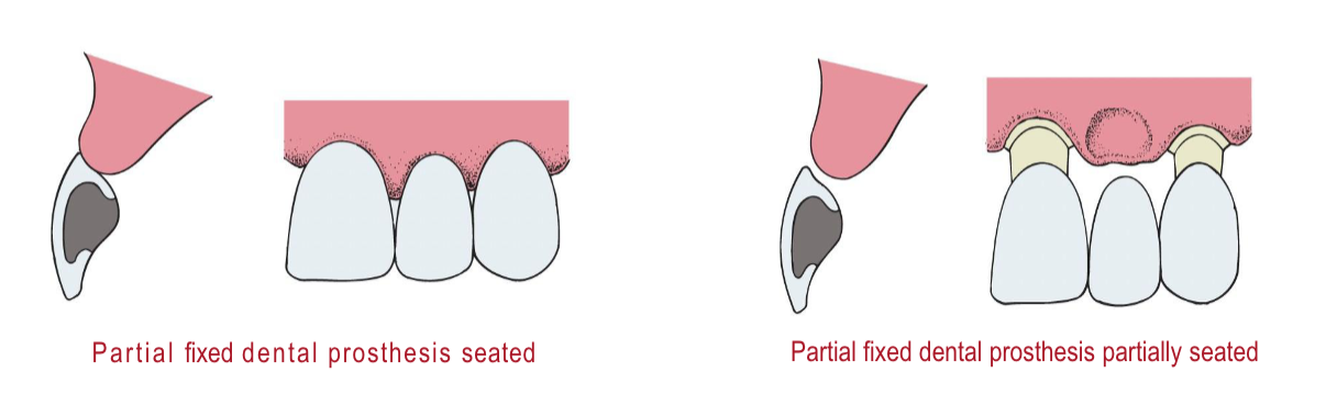
The path of insertion is an imaginary line along which the restoration is placed onto or removed from the preparation.
The abutments of a fixed partial denture must share a common path of placement, so the prosthesis can be seated without tooth
structure blocking the margins or intaglio surface
Path of Insertion — Three Planes
The abutment teeth MUST be parallel to each other in 3 planes:
1 — From the facial aspect
2 — Along the buccal corridor
3 — From the occlusal aspect *most important

If the abutments do not share a common path of insertion, or have undercuts, the fixed partial denture will not seat properly.
Path of Insertion — Evaluating with a Mirror
center the image of one preparation in the mirror.
move the mirror — without tilting — to the adjacent abutment until it is centered.
If the mirror's angulation must change to see the finish line of the adjacent tooth, the paths of insertion of the two preparations do not match.
Clinically, the path of insertion is verified by sighting along the prepared abutments before final impressions.
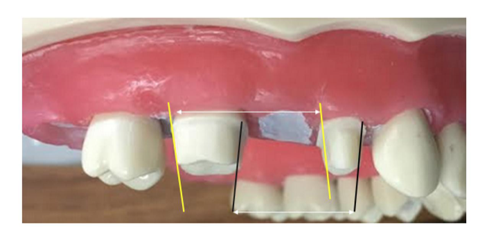
Taper of the distal surfaces of the abutments must be equal, as well as the mesial surfaces (6–8° per wall)
Pontic Design Classification
an artificial tooth on a fixed partial denture that replaces a missing
natural tooth, restores its function, and usually restores the space previously occupied by the clinical crown.
non mucosal contact
mucosal contact
Non-Mucosal Contact: 1. Sanitary/Hygienic
the primary design feature of the sanitary pontic allows easy cleaning because its tissue surface remains clear of the residual ridge.
This hygienic design lets gauze strips and other cleaning devices pass under the pontic in a shoeshine motion.
Disadvantage: entrapment of food particles, which may lead to tongue habits that annoy the patient — and the design is extremely unesthetic.
for generalized periodontitis
mucosal contact types
1. Conical
2. Ridge Lap
3. Modified Ridge Lap
4. Ovate
mucosal contact: Conical Pontic
The conical pontic is rounded and cleanable, but its tip is small relative to the overall size of the pontic — well suited to a thin mandibular ridge.
On a broad, flat ridge, the resulting large triangular embrasure spaces tend to collect debris.
May be unsuitable for broad residual ridges, where the small tissue-contact point creates areas of food entrapment
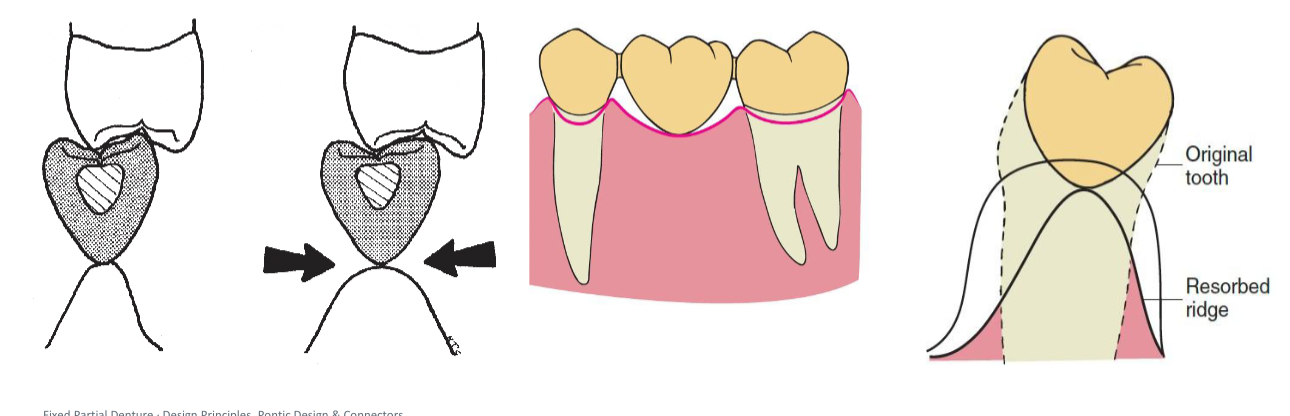
for thin/knife-edge ridge
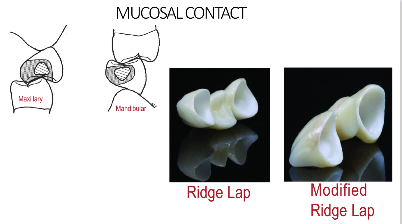
mucosal contact: Ridge Lap Pontic
The ridge lap pontic looks most like a natural tooth, replacing all the contours of the missing tooth and forming a large concave contact with the ridge.
This obliterates the facial, lingual, and proximal embrasures.
It is impossible to clean, because floss cannot traverse the tissue-facing area, and it causes tissue inflammation — it should not be used
mucosal contact: Modified Ridge Lap Pontic
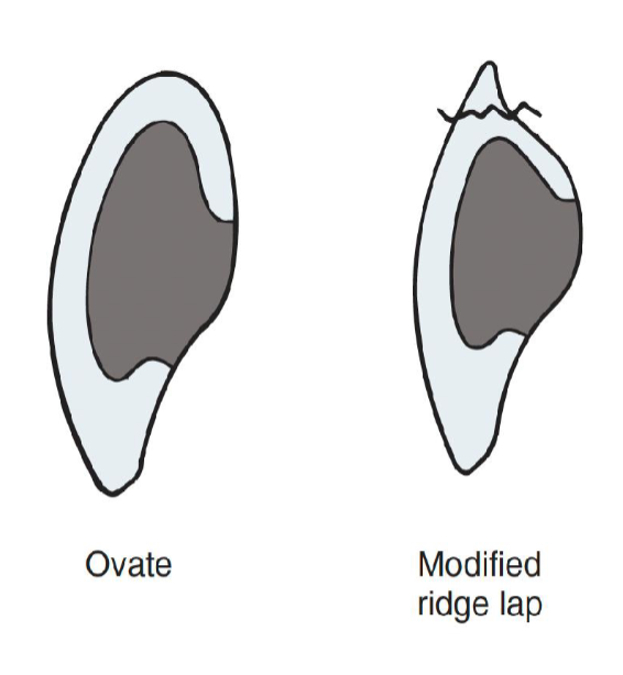
Gives the illusion of a natural tooth while possessing all or nearly all convex surfaces for ease of cleaning.
The lingual surface should have a slight deflective contour to prevent food impaction and minimize plaque accumulation.
A slight faciolingual concavity on the facial side of the ridge is acceptable, as long as tissue contact stays narrow mesiodistally and faciolingually
ex pictures
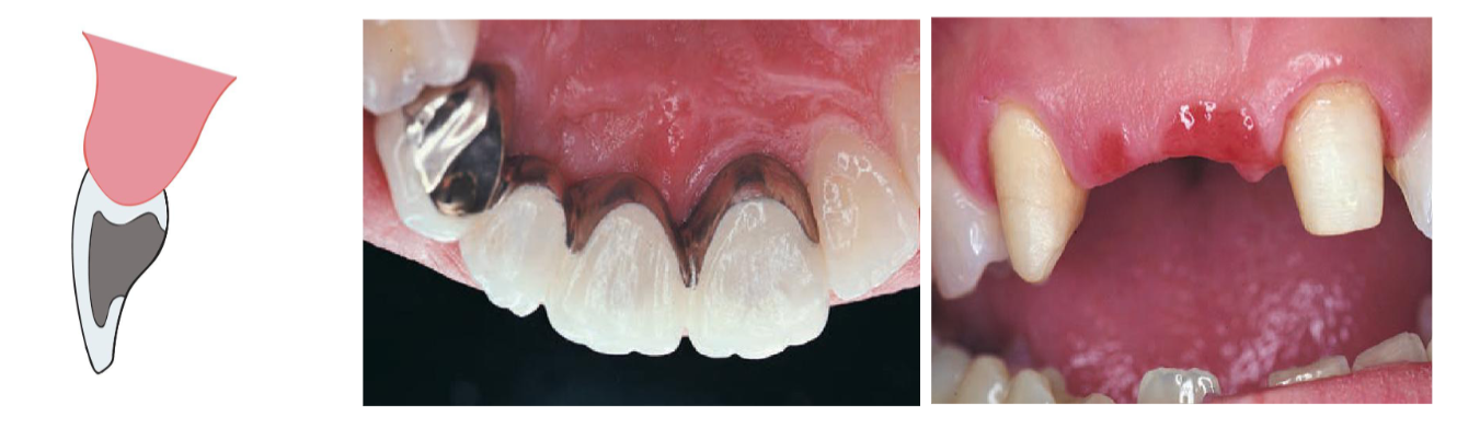
mucosal contact: Ovate Pontic — Design & Placement
The ovate pontic is a round-end design used where esthetics is a
primary concern.
The tissue-contacting segment is bluntly rounded and set into a
concavity in the ridge — it is easily flossed.
The concavity can be created by a provisional fixed partial denture extending one-quarter of the way into the socket immediately after extraction, or created surgically at a later time.
Works especially well with a broad, flat ridge, giving the appearance that the pontic is growing from the ridge.

do right after extraction, act likes an emergence profile (naturally emerging)
for esthetics (anterior)
Ovate Pontic — Advantages
Pleasing appearance and strength
When used successfully with ridge augmentation, its emergence from the ridge appears identical to that of a natural tooth.
Its recessed form is not susceptible to food impaction.
Its broad convex geometry is stronger than the modified ridge-lap pontic, because the porcelain at the gingivofacial extent of the pontic is supported
What Is a Rigid Connector?
Rigid connectors join abutments and pontics into one solid unit.
They can be produced by:
Casting, Soldering, Welding

Casting
shaped in wax before investing and casting.
Soldering
joined with an intermediate metal alloy.
Welding
joined directly with heat
Soldered Connectors
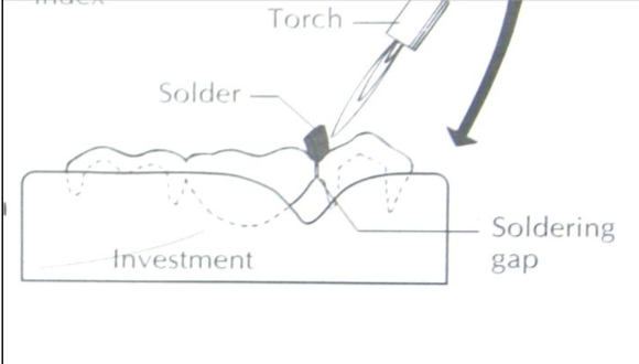
Soldering joins two or more metal pieces with an intermediate metal alloy that has a lower melting point than the parts being joined.
A torch heats the solder across the soldering gap while the assembly is held in an investment matrix to maintain position and prevent distortion
Welding Connectors
Another method of rigidly joining metal parts — by applying heat, pressure, or both, without a filler metal, to produce a localized union across the interface.
Spot welding — done by passing electric current through the parts.
Laser welding — based on a pulsed, high-power neodymium laser with very high power density.
Maximum penetration depth of these laser welding units is 2.5 mm
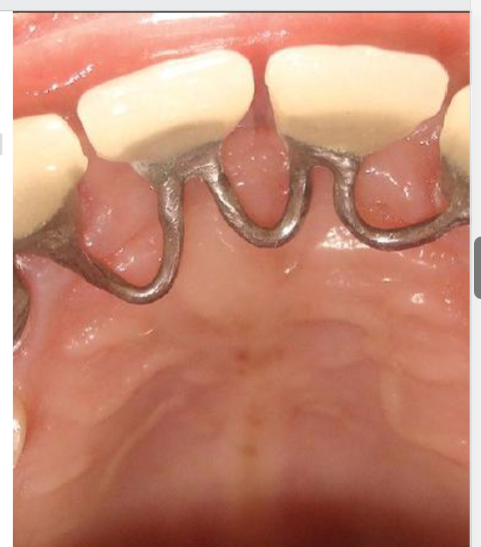
Loop Connectors
frequently required when an existing diastema must be maintained in the planned fixed partial denture.
The connector consists of a loop on the lingual aspect of the prosthesis, connecting the adjacent retainers and pontics
non-rigid connector
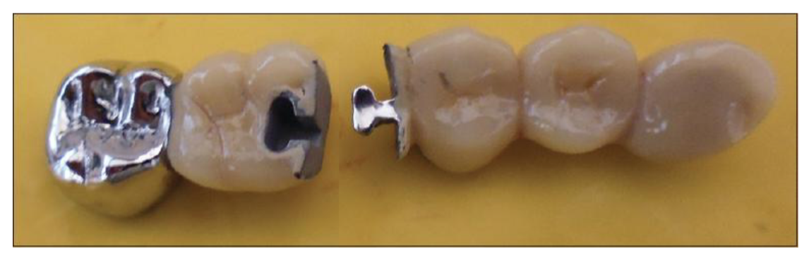
any connector that permits limited movement between otherwise independent members of a fixed partial denture (FPD)
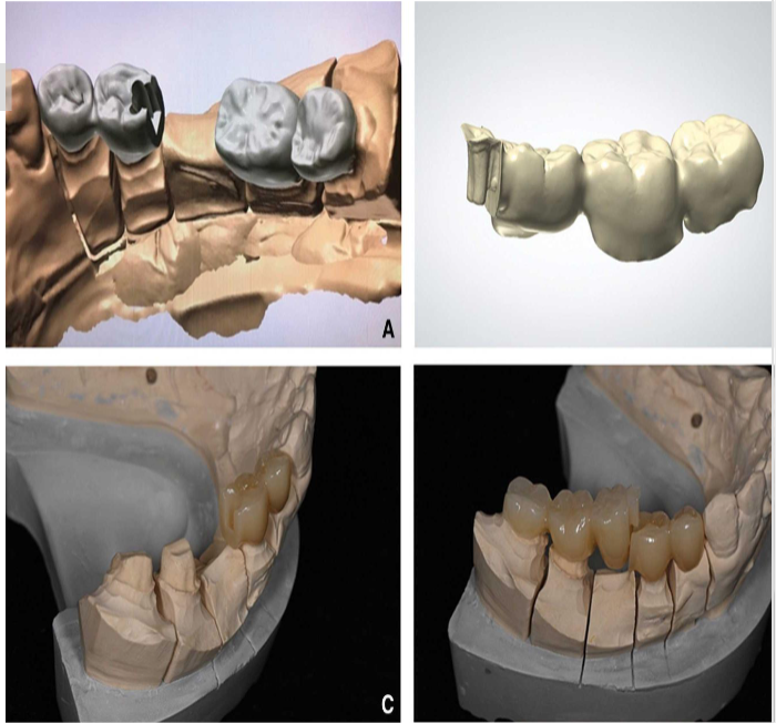
The Pier Abutment
also known as an intermediate abutment
a natural tooth located between terminal abutments.
It serves to support a fixed or removable dental prosthesis, and is a classic indication for a non-rigid connector to prevent leverage/torquing forces on the weaker terminal abutment
When Are Non-Rigid Connectors Used?
When it is not possible to prepare two abutments for an FPD with a common path of placement.
Segmenting large, complex FPDs into shorter components that are easier to replace or repair individually.
Mal-aligned abutment.
Questionable distal abutment — so only a portion of the FPD may need to be remade.
Types of Non-Rigid Connectors
Three working systems are used to let independent members of an FPD move relative to one another:
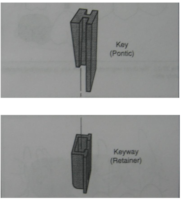
1. Dovetail (Key–Keyway)
A key on the pontic seats into a matching keyway on the retainer.
2. Split Pontic
The connector is placed entirely within the body of the pontic itself.
3. Cross Pin & Wing
A tapered pin locks the two segments together after cementation
Dovetail (Key–Keyway) Connectors
When an FPD is fabricated with a non-rigid connector, it is necessary to align the path of insertion of the keyway with that of the distal abutment.
This provides the best-suited solution for relieving stress at mid-span on pontics.
Dovetail Connectors — Placement
The key of the connector should be placed within the normal distal contours of the pier abutment.
The keyway should be placed on the mesial side of the distal pontic.
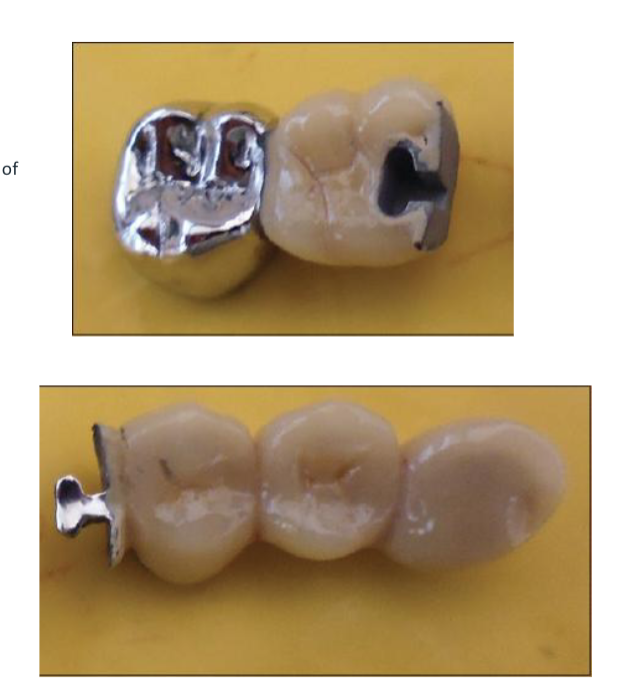
Split Pontic
An attachment that is placed entirely within the pontic.
Useful in tilted-abutment cases, where a conventional dovetail would require preparing a very drastic box.
A — the mesial segment has a distal shoe forming the
gingival portion of the pontic.
B — the distal segment covers the mesioocclusal part of
the pontic.

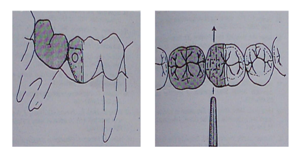
Cross Pin and Wing — The System
These are the working elements of a two-piece pontic system.
This allows the two segments to be rigidly fixed after the retainers have been cemented.
A — the distal retainer and wing are cemented first.
B — the retainer and pontic are seated last
Cross Pin and Wing — Sequence
A tapered pin is driven through the pontic, the wing, and back out from the pontic.
Once seated, this completes and rigidly locks the cross-pin-and-wing assembly.

Non-Rigid FPD — Clinical Benefits
Transfers shear stress to the supporting bone rather than concentrating it in the connectors.
Appears to minimize mesiodistal torquing of the abutments, while permitting them to move independently.
Components of a Fixed Partial Denture
Every FPD is built from the same core parts: abutment preparations
at each end, retainers cemented over them, and a pontic spanning
the edentulous ridge.
The connector joins pontic to retainer; together the retainers, connectors, and pontic form the framework (substructure) and superstructure of the prosthesis.
Key Takeaways
Abutment selection rests on crown-root ratio, root configuration, and periodontal ligament area — Ante's Law is the guiding rule.
Pontic span length matters biomechanically: deflection increases with the cube of the span, so longer spans risk far greater flexure.
A shared path of insertion across all abutments is non-negotiable, or the FPD will not seat.
Pontic design should minimize mucosal contact and maximize cleanability — the ovate and modified ridge lap are the modern standards.
Rigid connectors (cast, soldered, welded) unite the FPD into one piece; non-rigid connectors (dovetail, split pontic, cross pin & wing) allow controlled independent movement, especially with a pier abutment