Fundamentals of Manufacturing
1/212
There's no tags or description
Looks like no tags are added yet.
Name | Mastery | Learn | Test | Matching | Spaced | Call with Kai | Chat |
|---|
No analytics yet
Send a link to your students to track their progress
213 Terms
limits
the maximum and minimum values for a manufactured parts dimensions
tolerance
permissible variation in size or dimensions of a manufactured component
tolerance zone
difference between maximum and minimum allowable tolerance values
interchangeable manufacturing
parts are made nearly alike, so they can be used with the same functionality as part of a given mechanism
unilateral tolerance
deviation expressed in only one direction from the basic value

bilateral tolerance
deviation from basic value extends in both directions, can be equal or unequal
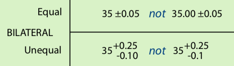
limit tolerance
deviation isn’t specified, only upper and lower limits are stated

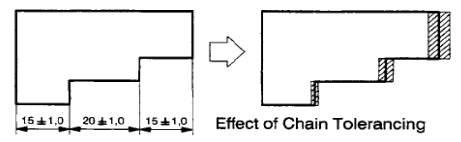
chain dimensions
individual dimensions are cumulative, so tolerances added to those dimensions are also cumulative
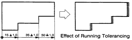
running dimensions
dimensions are all related to a datum surface, tolerance is the same for each running dimension, so overall tolerance is the same as for each running dimension
International Tolerance (IT) ranges
set by ISO 2768 standard, grades each manufacturing process, then use that grade and the base dimension to determine the tolerance range
fit
property of mechanical assemblies that determines the manner according to which manufactured components interact with one another
clearance fit
determines spacing between two mating parts, e.g. free spinning shaft in a non-moving hole
interference fit
mating parts have intersecting volumes, requiring their deformation for the desired assembly, e.g. rivets in an aircraft fuselage
transitional fit
limits of the fit are such that they may either be clearance or interference, functionality of the assembly is determined by other parameters
allowance
difference between the maximum and minimum material limits of mating parts, calculated by subtracting the upper limit of the shaft dimension from the lower limit of the hole dimension
basic size
intended theoretical dimension from which the limits are derived
manufacturing tolerance specification - hole basis
hole is machined to the lower limit specified and the shaft is the machined to meet the required fit
manufacturing tolerance specification - shaft basis
shaft is machined first, usually used when multiple components need to fit onto a singular shaft, shaft is manufactured to its upper limit and then holes will be machined to create the required fit
Metric engineering fits
done to ISO 286-1 standard, most used subclasses are: 5 clearance fits, 2 transitional fits and 3 interference fits
clearance fit subclasses - shaft smaller than the hole
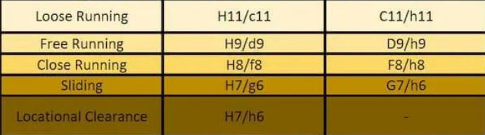
loose running fit
fit with largest clearance for applications where accuracy isn’t essential and the operating environment induces contamination, provides wide tolerances and allowances, e.g fits exposed to corrosion, dust contamination and high temperature cycles
free running fit
large clearance, applicable where the accuracy of the matching components doesn’t prompt special requirements, leaves room for movement in environments with heavy temperature fluctuations, high running speed and heavy plain bearing pressures, e.g. assemblies where films of lubricant must be maintained, shaft and plain bearing fits
close running fit
suitable for applications requiring small clearances and moderate accuracy, good for medium speeds and pressures, e.g. machine tools, CNC spindles
sliding fit
leave minimal clearance, used when high accuracy is needed alongside ease of assembly/disassembly, parts turn and slide freely, e.g. guiding of shafts, slide valves, machine tools, clutch discs, sliding gears
locational clearance fit
provides smallest clearance for high accuracy requirements, assembly doesn’t require force, matching parts can rotate and slide freely with lubrication, provides a snug fit for static parts, e.g. roller guides and guiding of shafts
transitional fit subclasses - shaft is slightly larger than the hole or clearance fit with small room for movement

similar (locational transitional) fit
used when accurate location is necessary, small interference or small clearance is suitable, e.g. wheel hubs, gears, pulleys, bearings
fixed fit
similar to similar fit (used when accurate location is necessary, small interference or small clearance is suitable) but assembly carried out with some light force, e.g. armatures on shafts, driven bushes
interference fit subclasses - larger shaft with a smaller hole

press fit
provides accurate alignment with minimal interference, assembly achieved with cold pressing, e.g. hubs, bushings, bearings
medium drive (driving) fit
requires higher assembly forces for cold pressing, or use hot pressing, produces a tighter fit, e.g. permanent mounting of gears and shafts
forced fit
high interference fit, assembly requires large temperature difference (hot hole and frozen shaft) to ensure forced shrink fit of the parts together, disassembly risks destruction of mating parts, e.g. gears, shafts
machining
manufacturing process involving the controlled removal of material - subtractive
CNC machining
Computer numerical control, automated control of tools via pre-programmed instructions to manufacture components
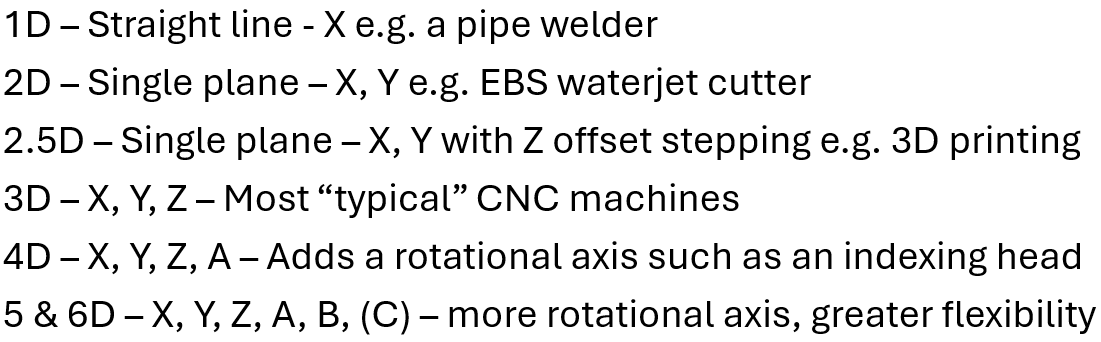
axis and dimensions for machining
relating to the number of degrees of freedom the toolhead can move in, generally cartesian coordinate system
fixturing
how the stock is held in the machine, helps to repeat things if the stock is held in the same way
stock
raw material the part will be cut from, produced in regular shapes, should be larger than the desired final part
work offset (G54)
reference point that bridges the gap between the CAM setup and the real world, good practice to choose a fixed repeatable point e.g. corner
incremental positioning (G91)
program dimensions or positions are given from the current point, how far away from where you want to be
absolute positioning (G90)
all dimensions or positions are given from a single reference point on the job, how far way from where it started
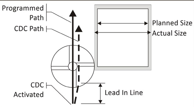
tool offset
required to ensure the machined part is the correct dimension, based on geometric information about the tool, offset lists, wear compensation
tools
end mills, slot mills, facing, tapping, boring, drilling, chamfering, inserts
radial tool offsets
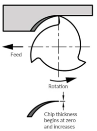
climb milling (left)
tool “climbs” along the material, large initial cut which thins as it progresses, rigid machine with backlash eliminators required, generally gives a better finish on most metal
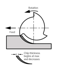
conventional milling (right)
rotating away from the material, thin cut getting thicker, manual or less rigid machines, can give better finishes on other materials
roughing
remove large amounts of material quickly creating a rough shape, high tool loading, tooling witness marks may be present, tool deflection, don’t rough to final size (always leave extra stock)
finishing
takes thin passes, achieves desired tolerance and mirror surface, not always required - need to think about the use of the part
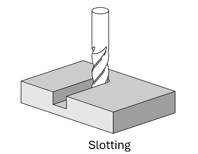
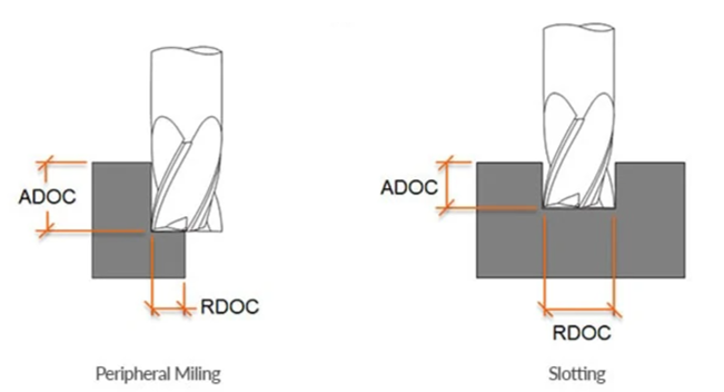
slotting
engages full diameter of the tool
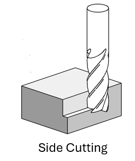
side cutting (shouldering)
doesn’t cross the centreline
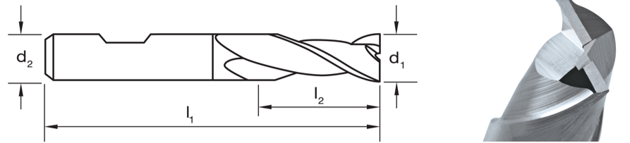
slot drills
1 tooth is longer than the other which helps provide continuous cutting, allows for plunging into material
drilling
a plunge operation
boring
rotational action for making precise round holes
tapping
engages a canned cycle that matches spindle speed and vertical feedrate to the pitch of the tap being used, stops and reverses the spindle direction to retract
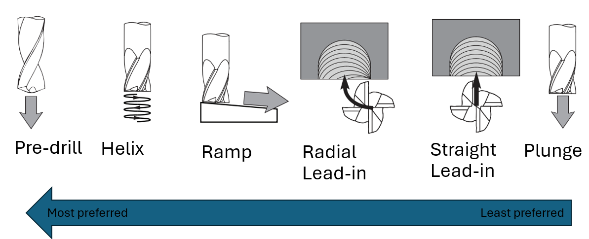
entrances and exits from materials
step over
radial depth of cut

step down
axial depth of cut
feed
rate of material fed in or rate of cutter advancement, expressed in mm/min
speed
spindle speed, rotational velocity of the tool (milling) or the workpiece (turning), expressed in r/min
facing
prepares raw stock for machining, regularising or squaring up, fast planar material removal, good for creating datum faces
contour
simplest operation, can be shoulder or slot milling, cuts a line along a contour of a fixed height, typically a finishing operation, multiple depths
classical roughing or finishing operation, contouring operation thats offset radially multiple times, toolpaths parallel to geometry, clearing areas
adaptive clearing
similar usage as pocketing, constant tool engagement - reduces shock loading of tool, less prone to breakages - longer tool life and reduced costs, creates a more complex toolpath - difficult to proram manually
chamfer
“breaking the edge”, uses a non-90 degree cutter, typically 45 or 60, an offset contour toolpath, eliminates sharp edges, safer to handle and aids in assembly
G-code
universal standard, commands that tell the machine what to do
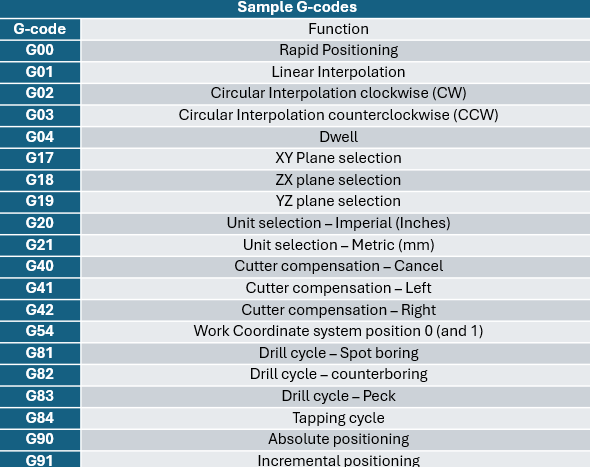
G00
rapid positioning
G01
linear interpolation
G02
circular interpolation clockwise
G03
circular interpolation counterclockwise
G04
dwell
G17
XY plane selection
G18
ZX plane selection
G19
YZ plane selection
G20
unit selection - imperial
G21
unit selection - metric
G40
cutter compensation - cancel
G41
cutter compensation - left
G42
cutter compensation - right
G81
drill cycle - spot boring
G82
drill cycle - counterboring
G83
drill cycle - peck
G84
tapping cycle
M-code
differs between machine, but focuses more on the program rather than the actual machining process
M00
program stop
M01
optional stop
M02
end of program
M03
spindle start - forward clockwise
M04
spindle start - reverse counterclockwise
M05
spindle stop
M06
tool change
M08
flood coolant on
M09
coolant off
M30
end of program (return to top of memory)
T
tool (followed by number or description)
F
feedrate (m/min)
S
spindle speed (rpm)
conventional machining
hard, sharp tools, in contact with workpiece, human driven input
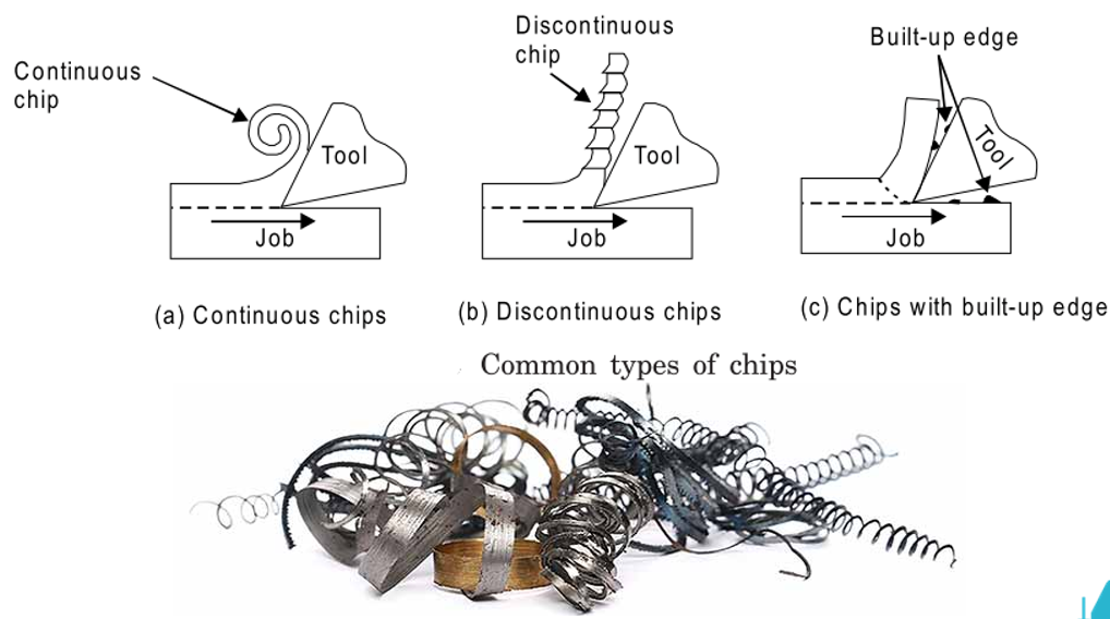
chips
made in some form by removing material to make the part
causes of wear
excessive heat (tempering), abrasion (dulled edges), build up on tool edge (galling), clogging of flutes (galling), chipping of tool (overloading), workpiece work hardening (rubbing and glazing)
effects of wear
damaged tools, bad surface finish, reduced efficiency
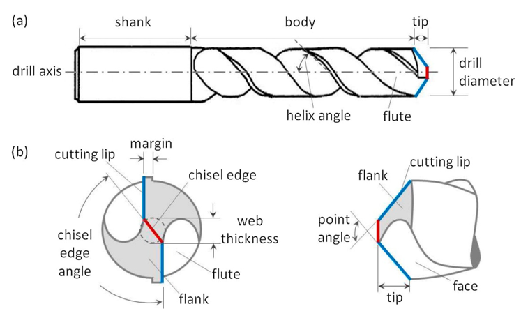
twist drill
rapid material removal, only cuts axially, ‘round’ but not precision holes, tip angle - 118 typical, 140 for harder metals, 60 for softer woods, cutting lip cuts and chisel lip deforms, helix angles - slow, standard, quick