Part 2 Module 8 / application of health & safety and electrical principles
1/23
There's no tags or description
Looks like no tags are added yet.
Name | Mastery | Learn | Test | Matching | Spaced |
|---|
No study sessions yet.
24 Terms
How production of energy in a polyphase system works (power station)
Most electricity in the UK is produced in power stations by having the shaft of a three-phase alternator (AC generator) turned, in the majority of cases, by using steam. In power stations, water is heated until it becomes high-pressure steam. A variety of energy sources can be used to heat the water. The more popular ones are coal, gas, oil and nuclear power. The steam is forced through the vanes of a turbine, which then rotates an alternator.
Alternative methods of power generation include wind power and high pressure jets (hydro-electric power).
Volt drop formula
Vd = I x R
Therefore, if a supply cable was carrying a current of 2000A and the resistance of the cable was 2 Ω, then 4000 volts would be dropped over the length of the supply cable. It can be seen then that transmission at low voltage values with high currents would mean the installation of very large cables and switchgear indeed.
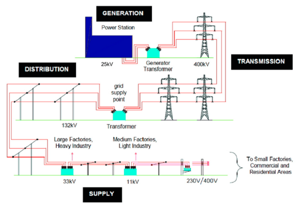
What is the national grid?
The National Grid is a network of nearly 5000 miles of overhead and underground power lines that link power stations together. This network is interconnected throughout the country.
The transmission network transports electricity from generation units to distribution companies and a small number of large industrial customers. The distribution companies then deliver electricity to the majority of customers through lower voltage networks. It is done this way so that if a problem occurs from one power station or line, power can flow from another. Electricity is transmitted around the grid, mainly via steel-cored aluminium conductors which are suspended from steel pylons
The cost of installing cables underground is excessive.
Air is a very cheap and readily available insulator.
Air also acts as a coolant for the heat being generated in the conductors.
How does electricity go from distribution to small factories, commercial and residual supply areas?
These regional substations will transform the grid supply from 400kV from transmission down to 132kV to distribute electricity at this level to a series of local substations. The local substations take the 132kV supply, transform it down to 33kV then 11kV then 230V/400V.
Its then distributed via a network of underground radial circuits to the customer. However, in rural areas this distribution sometimes takes place using overhead lines. It is also at this point that you would see the introduction of the neutral conductor. This is normally done by connecting the secondary winding of the transformer in a star and then connecting the star point earth via an earth electrode beneath the substation.
How distribution to the customer works
Once the electricity has left the local substation, it will become reduced to a usable voltage level and then eventually arrive at the customer at. This is called the main intake position. You will find certain items in the main intake position that belongs to the supply companies. These items are:
An energy metering device which determines the customer’s electricity usage.
A sealed over-current device that protects the supply company’s cable.
Once past this point we have reached consumers installation. The consumer’s installation must be controlled by a main switch, which must be located as close as possible to the supply company equipment and be capable of isolating all phase conductors. In the average domestic installation this device is merged with the means of distributing and protecting the final circuits in what is known as the consumer unit.
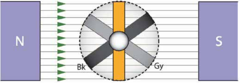
How a three phase supply created?
When an emf is generated it is done so by spinning a loop of wire inside a magnetic field. To get three phases, you have to spin three loops inside the magnetic field. Each loop will be mounted on the same rotating shaft but the loops will be 120 degrees apart.
Each loop creates its own waveform so they each have their own voltage, each 120 degrees apart. If the loads are not balanced then the three phase supply needs a fourth cable being the neutral.
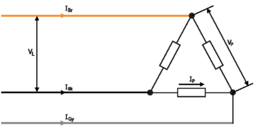
How is a delta connection and how is it designed?
When there is a balanced load like in a transmission from power station or to connect the windings of a three-phase motor. A delta connection is used because there is no need for a neutral connection and therefore only three wires are needed.
Each leg of the load has been connected across two of the lines this is known as the line voltage (VL).
As each line voltage is pushing current along, this is referred two as being line current (IL).
These line currents are calculated as being the phasor sum of two phase currents, which are shown on the drawing as (Ip) and represent the current in each leg of the load.
The voltage across each leg of the load is referred to as the phase voltage (Vp).
In a delta-connected, balanced three-phase load, it is then possible to state the following formulas:
VL = Vp and: IL = √3 x Ip
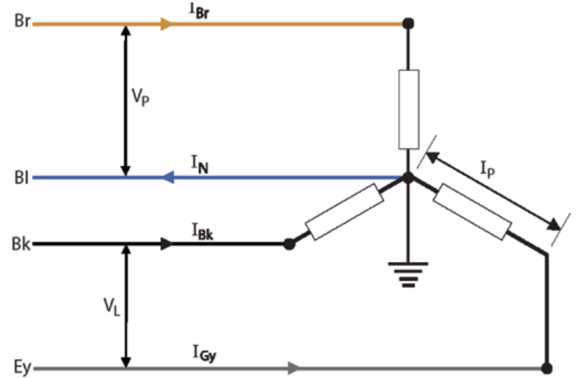
In a star-connected load, the line currents and phase currents are the same (IL = Ip). but the line voltage (400 V ) is greater than the phase voltage (230 V ) (VL = √ 3 x Vp)
How does a star connection work?
The star connection is generally used for unbalanced loads. All three star-connected loops are connected to a central point and it is from this point that the neutral connection is taken, which in turn is connected to earth. This is known as a three phase, four wire system.
star and delta connections are relatively the same except from the Voltage phase exists between any phase conductor and neutral conductor.
Advantages to using a star connection over a delta.
A 3-phase star connected transformer feeds a delta-connected 3-phase load. If the star-connected phase voltage is 230 V and the phase current is 40 A, calculate the Star connection Line voltage (VL) and line currents (IL).
In a star-connected system the line current is the same as the phase current (IL = Ip).
So, Ip = IL = 40 A
Also, in a star connection , the line voltage is √3 (1.732) times larger than the phase voltage (Vp):
VL = √3 x Vp= 1.732 x 230 V = 398 V (pretty close to 400 V )
Star connection is just delta connection switched from divide to times.
A 3-phase star connected transformer feeds a delta-connected 3-phase load. If the star-connected phase voltage is 230V and the phase current is 40A, calculate the delta connection line (VL) and phase (Vp) voltages and currents (Ip).
In a delta-connected system, the line current (IL) is √3 (1.732) times greater than the phase current (Ip), expressed as: IL = √3 x Lph.
The load is supplied at 40A (IL) per phase at 400V.
By transposition: Ip = IL / √3 = 40A/1.732 = 23.1A
In a delta connection, VL = Vp
Therefore: VL = Vp = 398 V (400 V)
Delta connection is just star connection switched from times into divide.
Three identical loads of 50Ω impedance are connected first in star and then in delta to a 400V, 50Hz, 3-phase supply. Determine the phase and line currents.
Star connection:
The phase voltage (Vp) needs to be determined:
VL = √ 3 x Vp
By transposition: Vp = VL / √ 3 = 400 / 1.732 = 230.9V (230V)
Use Ohm’s law to determine phase current:
Ip = Vp / Zp = 230V / 50 = 4.6 A
In a star-connected load: Ip = IL therefore: IL = Ip = 4.6 A
In delta connection:
VL = Vp = 400V
Use Ohm’s law to determine phase current:
Ip = Vp / Zp = 400V / 50Ω = 8A
The line current is √3 (1.732) times greater than the phase current:
IL = √3 x Ip = 1.732 x 8 A = 13.86 A
As can be seen from the results, the current drawn from a delta-connected load (13.86A) is three times that of a star-connected load (4.6 A).
How a load from a three phase four wire system is balanced
Loads have to be balanced in a 3 phase 4 wire system so that the designer can use the proper sizing for the main cable so that costs are reduced and also so the switchgear can be kept to a minimum. The designer can do this by subdividing the load categories so that the maximum demand can be assessed. Items of equipment can be spread over all three phases of the supply to achieve a balanced system.
Standard circuit arrangements exist for many final circuits operating at 230 volts. For example, a ring final circuit is rated at 30 A/32 A, a lighting circuit at 5 A/6 A, and a cooking appliance at 30 A/32 A to 45 A. Where more than one standard circuit arrangement is present, such as three ring final circuits and/or two cooking appliances, then a diversity allowance can be applied.
Once the designer has made any allowances for diversity, the single-phase loads can be evenly spread over all three phases of the supply so that each phase takes approximately the same amount of current.
What are protective device’s two most typical faults
Earth faults – over currents between any live conductor and earth.
Short circuits between live conductors – line to neutral single-phase, line to line three-phase.

How design current (IB) is calculated
Single-phase supplies:
Uo = 230V (phase voltage to earth) (supply voltage).
Ib = Power / Uo
Three-phase supplies:
Uo = 400V
Ib = Power / √3 x Uo
However in an AC circuit poor power factor (PF) can be produced, so you would have to take that into account. You can do this by multiplying the bottom part of the equation by the PF for both single and three phase supplies.
Types of protective devices and how they can affect their disconnection time.
Thermal tripping – the load passes through a small heater coil wrapped around a bi-metal strip. When the current is too high, the strip rises and trips the latch.
Magnetic tripping – a magnetic field is set up around a flexible strip. When the current is too high the latch is operated
Some systems will only feature small overloads, where a sudden shutdown of power may cause more damage. Thermal tripping is more advisable. Thermal tripping naturally takes longer than magnetic tripping, as it relies on a build up of heat. magnetic can trip almost immediately.
What is a t (PSC/PFC), the causes and the affects of this?
A short circuit is an unintended electrical path with low resistance, causing excessive current flow. This can happen due to damaged wires, faulty connections, or insulation breakdown, leading electricity to bypass its intended path and flow through a shorter, low-resistance route.
Possible causes of the occurrence of a short circuit fault are:
Accidental damage
Contact between two poles of the supply due to incorrect connection.
Equipment failure
Ingress of moisture
The effects of short circuit current are:
The heat, or thermal, effect, which can cause alteration of the properties of materials, melting of conductors/insulation, fire, etc.
The mechanical effects of large magnetic fields that can build up when short circuit currents are flowing, resulting in conductor distortion, breaking of supports/insulators, etc.
This is the worst case scenario of a short circuit fault and rapid disconnection of the supply is essential to prevent damage.
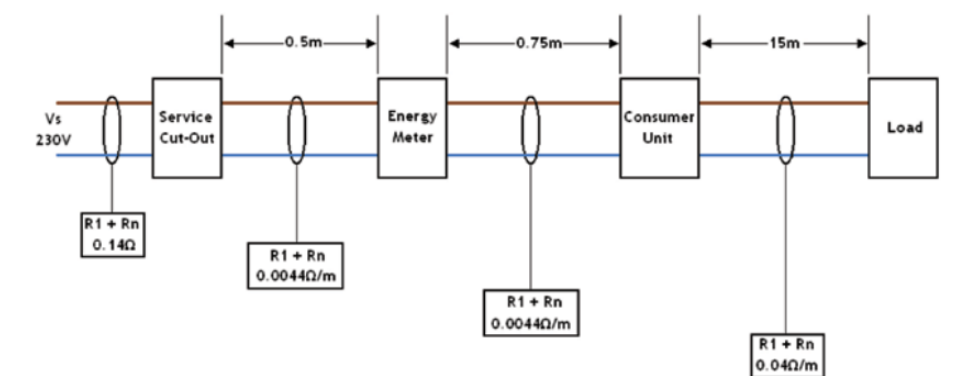
Calculate the prospective short circuit current (PSSC) flowing in the circuit shown at the terminals of the:
a) consumer unit
b) load - under the conditions shown
(all resistances quoted are for combined line and neutral conductors)
a) At the terminals of the consumer unit:
Rt = 0.14 Ω + (0.5 m x 0.0044 Ω) + (0.75 m x 0.0044 Ω) = 0.1455 Ω
PSSC = Vs / Rt = 230V / 0.1455 = 1580.76 or 1.58 kA
b) At the terminals of the load:
RT = 0.1455 Ω + (15 x 0.04 Ω) = 0.7455 Ω
PSSC = Vs / Rt = 230V / 0.7455 = 308.52 A or 0.31 kA
For consumer unit, add each R1 and R2 plus their cable distance from the start of the circuit to the consumer unit, then divide it by 230V. Then for terminals of load, add existing value to the R1 and R2 and the cable distance from the consumer unit to the load, Then again divide by 230V.
Rating of the protective device (In)
Once you have worked out the design current of the circuit (Ib), you must next work out the current rating or setting (In) of the protective device.
Regulation 433.1.1 in the IET Wiring Regulations says that current (In) must be no less than design current (Ib) of the circuit. This is because the protective device must be able to pass enough current for the circuit to operate at full load, but without the protective device operating and disconnecting the circuit.
The table you use to select the value of your protective device will depend on the type of equipment or circuit to be supplied and the requirements for disconnection times.
What are protection devices and how they should be chosen?
Protective devices are designed to operate when an excess of current passes through it. The Regulations categorise equipment short lived overloads as overload current and overcurrent. For conductors, the rated value is the current-carrying capacity. Most excess currents are, however, due to faults, either earth faults or short circuits, which cause excessive currents.
The rating of a protective device should be greater than, or at least equal to, the rating of the circuit or equipment it is protecting. For example, a portable domestic appliance which has a label rating of 2.7 kW equates to a total current of 11.74 amperes, therefore a fuse rated at 13 amperes should be fitted in the plug.
Faults that result in a high rise in temperature destroys insulation properties which could risk a short circuit. Where as, high currents damage equipment, and earth-fault currents are associated with the risk of electric shock. A suitable disconnection device should be chosen and installed.
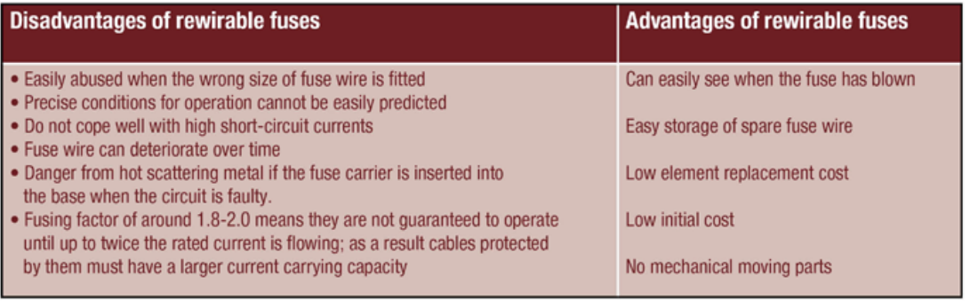
What are BS 3036 semi-enclosed rewireable fuses , made of, pros and cons of this fuse and how are they colour coded?
The rewireable fuse consists of a fuse, a holder and a fuse carrier (both made of porcelain or Bakelite) and a fuse element. The circuits for which this type of fuse is designed have a colour code marked on the fuse holder as follows:
5 A white
15 A blue
20 A yellow
30 A red
45 A green
However, this fuse has some disadvantages which are shown in the picture.
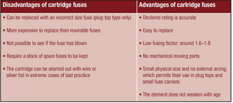
What are BS 1361 / 1362 cartridge fuses made from and what are their pros and cons?
This type of cartridge fuse consists of a porcelain tube filled with granulated silica. The metal end caps are attached to the element.
The BS 1362 fuse is most often found in domestic plug tops used with 13 A BS1363 domestic socket outlets. The two most common fuse ratings available are the 3 A, which is for use with appliances up to 720 watts (e.g. radios, table lamps, electric blankets, etc.) and the 13 A fuse, which is used for appliances rated over 720 watts (e.g. irons, kettles, fan heaters, electric fires, white goods and vacuum cleaners).
The BS 1361 fuse is normally found in distribution boards and at main intake positions. However, this fuse has some disadvantages which are shown in the picture.
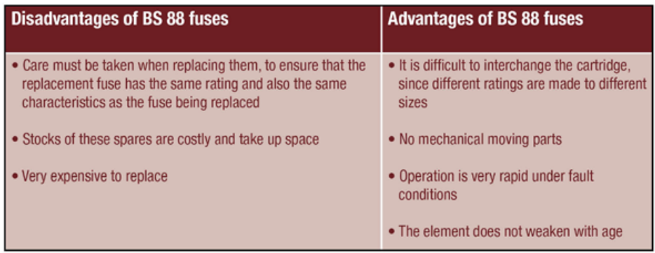
What is the BS 88 high breaking capacity (HBC) fuse made from, its features and pros and cons?
The HBC fuse is a variation of the cartridge fuse consisting of a porcelain body filled with silica, a silver element, and lug-type end caps. It is usually found protecting motor circuits and industrial installations.
Another feature of this type of fuse is the indicating bead, which shows when the fuse element has blown. It is a very fast acting fuse with the ability to discriminate between a starting surge and an overload.
This type of fuse would be used where there is a likelihood of abnormally high prospective short-circuit currents
However, this fuse has some disadvantages which are shown in the picture.
Selectivity of protection devices for a circuit
There are usually a series of fuses and/or circuit breakers between the incoming supply and the electrical outlets. The relative rating of the protective devices used will decrease the nearer they are located to the current-using equipment.
Ideally, when a fault occurs, only the protective device nearest the fault will operate or ‘trip’, thus ensuring as little disruption as possible to other circuits not associated with the fault. This type of behaviour within the system is known as selectivity. Selectivity is also known as the co-ordination between fuses. Selectivity is said to have taken place when the smaller rated local device operates before the larger device.
Selectivity is generally only a problem when a system uses a mixture of devices. As a general rule, when fuses are used in series in an installation, a 2:1 ratio with the lower-rated devices will be satisfactory.