CAE pt. 1
 Call Kai
 Learn
Learn Practice Test
 Spaced Repetition
 Match
Match Flashcards
 Knowt Play
1/42

Earn XP
Description and Tags
Mechanical Engineering Drawings
Name | Mastery | Learn | Test | Matching | Spaced | Call with Kai | Chat |
|---|
No analytics yet
Send a link to your students to track their progress
43 Terms
sketch
principal dimensions shown
no tolerances
no drawing or revision number
no “drawn by“ or “approved by“
detail drawing
all dimensions shown
formatted title block: drawing and revision number, “drawn by“, “approved by“
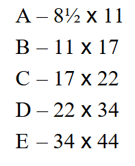
standard drawings (inches) A-E
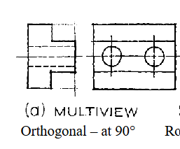
multiview
three orthogonal views
isometric view
corners at 120 degrees, 30 degrees from flat surface

dimetric view
corners at 150 degrees, 15 degrees from flat surface

trimetric view
front corner at 105, right corner at 135, top corner at 120
left side 15 degrees from bottom, right side 45 degrees from bottom

ANSI projection (third angle)
Front view is key view, top view is above fromt view, right view is to the right of the front view, left view is to the left of the front view, bottom view is below the front view


projection symbols

visible line
thick
used to depict visible edges

hidden line
dashed line representing edges of the object that are not visible in that view

section line
thin, continuous diagonal lines used to identify the surfaces of an object that lie on the cutting plane

center line
thin, dashed lines used to indicate the central axes of cricular features or geometries
alternating long and short dashes that extend beyond the edges of the object

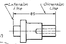
dimension and extension lines
dimension lines are thin, continuous lines with arrows or ticks at the ends that include a numerical value indicating the dimension of a feature
extension lines extend from the object’s edge or a central line to the dimension line
cutting plane or viewing plane lines
thick, dashed lines with arrows on the end (showing line of sight) used to descrive where a section is cut through an object and the direction of sight.

phantom line
thin, dashed lines that indicate the range or extent of motion of a moving feature

dimensioning rules (6)
each dimension should be given clearly, so that it can be interpreted in only one way
dimensions should not be duplicated, and no dimensions should be given except those needed to produce or inspect the part
dimensions should be given between points that have a functional relation to each other or that control the location of mating parts
avoid dimensioning hidden lines whenever possible
the longer dimensions should be placed outside all intermediate dimensions so that dimension lines will not corss extension lines
do not expect workman to assume a feature is centered, but give a location dimension from one side

tolerance
the permissible limit of variatuon in a physical dimension. certain tolerances are requires by engineering standards, especially between mating components
hole based system
size of hole is kept constant, shaft size is varied to get different fits
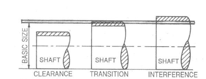
shaft based system
size of shaft is kept constant, hole size is varied to get different fits
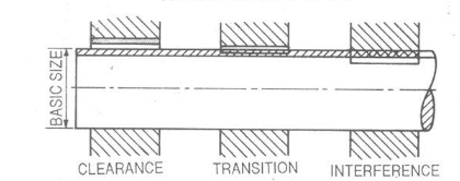
close sliding fit
RC1: accurate location of parts that must assemble without perceptible play
sliding fit
RC2: parts that will move and turn easily but are not intended to run freely
precision running
RC3: precision parts operating at slow speeds and light loads that must run freely
close running fit
RC4: accurate location with minimum play for use under moderate loads and speeds
medium running fit 1
RC5: accurate machine parts for higher speeds and/or loads
medium running 2
RC6: rimilar to RC5 for applications in which larger clearances are required
free running fit
RC7: reliable relative motion under wide temperature variations in which accuracy is not critical
loose running fit 1
RC8: permits large clearances, allowing the use of parts with commercial, “as recieved“ tolerances
losse running fit 2
RC9: similar to RC8 with approximately 50% larger clearances
interference fits
the inside member is larger than the outside member, requiring the application of force during assembly
forcce and shrink fits

limit dimesnioning
upper and lower limits (small difference)

plus and minus dimensioning
base dimension with a plus and minus

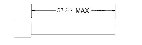
single limit dimensioning
min or max to one dimension
required in title block
drawing name
drawn by
name and handwritten initials
date
drawing number
required in drawing, not necessarily in title block
unit system
scale
detail drawings
exact drawing that provides all the dimensions, tolerances, materials, and manufacturing instructions needed to fabricate a single component
production drawing
official document that gives exact instructions on how to build, measure, and inspect a part
assembly drawings
technical illustration that shows how multiple individual parts fit and dunction together to form a complete product or subassembly
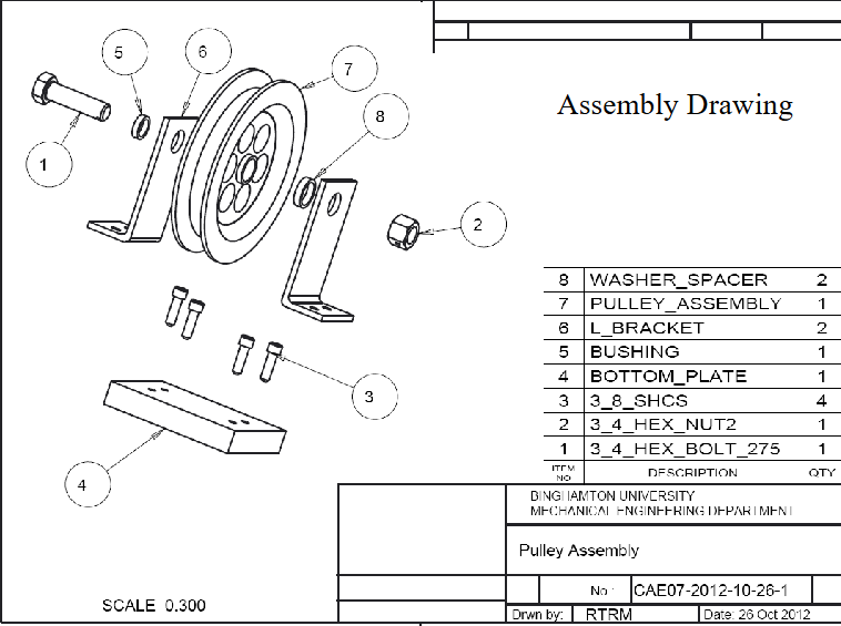
bill of materials
needed for assembly drawings
numbered parts (standard and purchased)
standard part
a part whose dimensions, material, and properties are completely specified in an international or national standard
purchased part
made by an original equipment manufacturer (OEM), usually following national or international manufacturing association standards or guidelines
standard part
the designation of these parts is specified in the standard
they are not designated by a vendor’s part number
ex. bolts, screws, rivets, pins, washers, etc
part drawings
standard parts do not require detail drawings unless modified, and do not require a technical specification sheet
purchased parts do not require detail drawings, but do require a technical specification sheet